FFS Brands VIHD2 User manual

Hot Dog Grill 2
VIHD2
Hot Dog Grill 4
VIHD4

HOT DOG GRILL 2 SPECIFICATION PAGE
MODEL VIHD2
Dimensions
Height
Width
Depth
Machine
188mm
526mm
480mm
Weight 15kg
Electrical
Running Amps
Connection Type
International Option
1kw, 1 phase, 50HZ AC, 230v
4.4 Amps
2m BESCHUKO Euro cable with,
MFEUROCONVERT Euro to UK converter plug
N/A

HOT DOG GRILL 4 SPECIFICAION PAGE
MODEL VIHD4
Dimensions
Height
Width
Depth
Machine
188mm
811mm
480mm
Weight 21kg
Electrical
Running Amps
Connection Type
International Option
2kw, 1 phase, 50HZ AC, 230v
9 Amps
2m BESCHUKO Euro cable with,
MFEUROCONVERT Euro to UK converter plug
N/A

Assembly Instructions
1. Remove protective plastic covering from all surfaces.
2. Remove grid and wash in hot soapy water, rinse and dry.
3. Clean all surfaces with a clean, hot, damp cloth.
4. Replace grid on drive studs.
Installation
Position the
Hot Dog Grill
near a suitable electrical supply; ensure that the electrical cable
cannot cause a tripping hazard etc.
Operating Instructions
Turn RED switch 'ON', the digital control will display a temperature and then the grid will
travel up and down, heating will commence.
Allow 20 minutes for grill plate to pre-heat.
Temperature control is factory pre-set at 90°C.
Using tongs, place hot dogs/frankfurters between roller bars. Product will be ready to
serve in 10-15 minutes, depending on size and thickness. Recommended internal
temperature of product should be 68°C - 70°C.
NEVER LEAVE TONGS ON OR BELOW A MOVING GRID.
Note:
All HOT DOG GRILLS operate on a "heat n' hold" principle. The pre-set grill plate
temperature will heat the hot dogs in a matter of minutes and hold them for several hours
with little or no deterioration in appearance or taste. If there are any early signs of
deterioration, the grill plate temperature should be lowered, see "GRILL PLATE
TEMPERATURE" instructions.
Grill plate temperature
The grill plate temperature has been factory pre-set at 100°C. This operating temperature
can be adjusted between 90°C and 110°C. To change the temperatures proceed as follows:
To set an operating temperature between the factory set parameters. Push and
hold “SET” button
and with the -and the - button set the required temperature.

Setting and changing controller parameters
Press and hold, in sequence, the + SET +keys
After 3 seconds SCL will be displayed
The key will allow you to step through the parameters
Use the key t step back if required
To read the current setting of a display parameter press the SET key
To change the current set parameter, when displayed press and hold the SET
key and with the or
keys enter the required parameter settings.
To exit from the set-up press the key
Note: - When the controller is ON the ISP (set working temperature) can be
adjusted between the
SPL and SPH (min and max temp) by pressing and holding the SET key and
resetting the temperature with the keys.
Cleaning daily
Switch power OFF, and remove electrical cord from wall supply.
Allow unit to cool.
Remove the Grid and wash thoroughly in hot soapy water, using a soft brush.
Whilst Grill Plate is warm, clean with a soft, clean cloth wrapped around a small quantity
of ice chips (try it! it works!). Dry thoroughly.
The Grill Plate has an anodised coat. Do NOT use any abrasive materials, scouring pads or
sharp implements to remove food residue, these will damage the plate's surface and
invalidate the warranty.
Do NOT use bleach
Clean all stainless steel surfaces and control panel with proprietary stainless steel cleaner
and a soft, damp cloth. Dry thoroughly. Replace GRID on drive studs.
Note: Do not use abrasive cleaners or pads.
Do NOT use bleach

Spare Parts Listing
PART NO. DESCRIPTION QTY. IMAGE
BESCHUKO H05Rr-F 2Mtr. Rubber C032 1
MF13701NAT Natural Polyoxymethelyne Push-In Rivets
137001000005 8
MF817-8877 Black Nylon 66, strain relief cable bush 1
MF354Z 2 Pole 5amp term block TB06 1
MF464-9845 3 Way Ceramic Block TB08 1
MF543-204 9.5mm Grommet 1
MF605-649 Grommet 1
MFCOMMON2 Label 9 280 x 60 1
MFEUROCONVERT Euro to UK converter plug In black 19-1032 1
MFFF-001 Richco Round Fixed Height Feet, 24mm, 14mm,
TPE 4

PART NO. DESCRIPTION QTY. IMAGE
MFINSHD2 Hot Dog 2 Insulation 1 Oos
MFMOTOR/GEARB
OX Motor/Gearbox 80 547 019 1
MFMTR11TIRES Ltr-5Tsre-A(P) Digit Therm. With Probe 1
MFV05-09T Drive bush with thread 2
MFV05-18 Drive link 1 (Cmp) V05-18 1
MFV05-24 Reciprocator wheel Vc-01 2
MFVC-07 Drive Pin VC-07 2 Z63b4
MFV12-25 Ali drive link large 2
MFVC-13 Sneeze screen location 4
MFVC-14 Socket drive Sh/MSM4GY1011SS0100 4
MFVC-25 HD2 / HD4 element 1Gikin363001 1
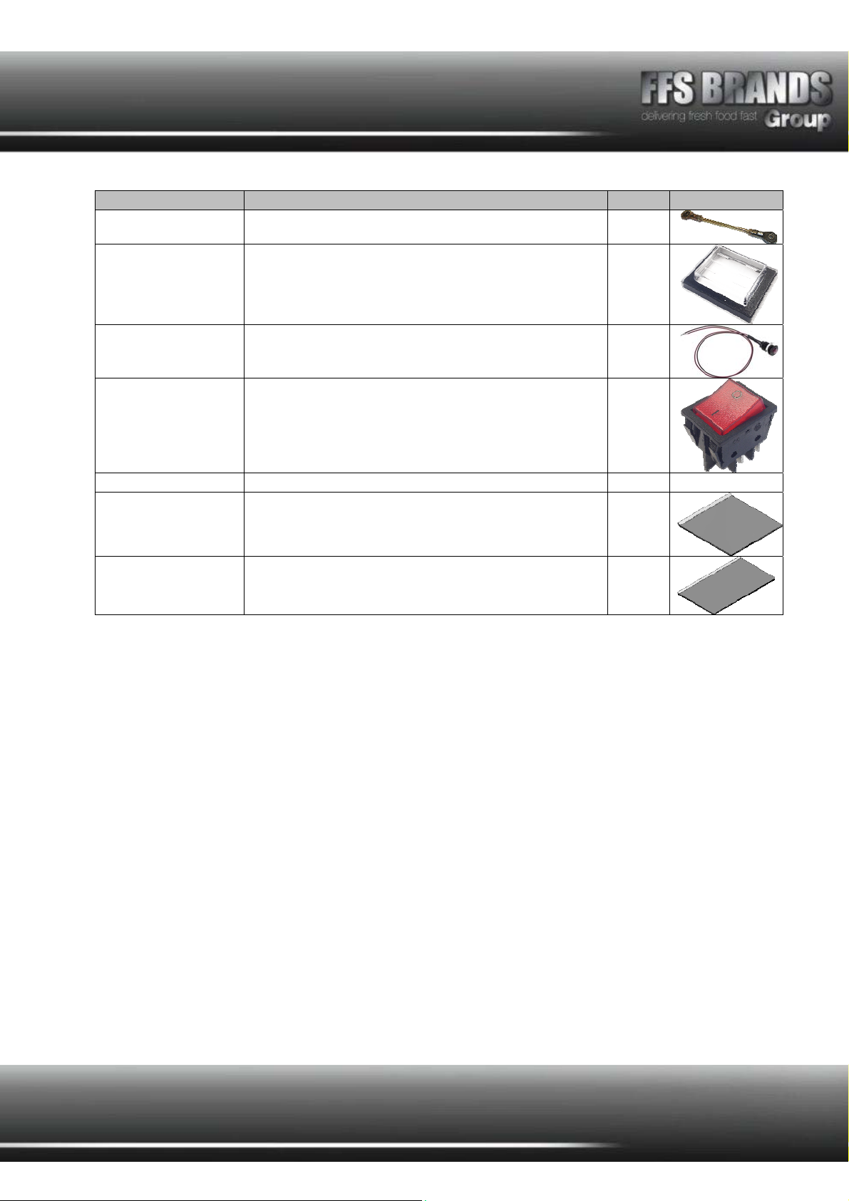
PART NO. DESCRIPTION QTY. IMAGE
MFVC-27 Drive shaft assy with 2 rod ends & thread 1
VILE14 Switch cover / bezel HD2/HD4 MFF1025 / MF1026 1
MF374-1029 10mm low profile lens indicator 230VAC 1
VISW17 Rocker switch HD2 Revolva HD4 MFC1553ALR 1
MFSTEGCAP Capacitors (204-4939) 1 Y3shelf3
MF05-
01ANODISED Reference - Cooking platen for HD2 1
MF07-
01ANODISED
Reference - Cooking platen for HD4 1
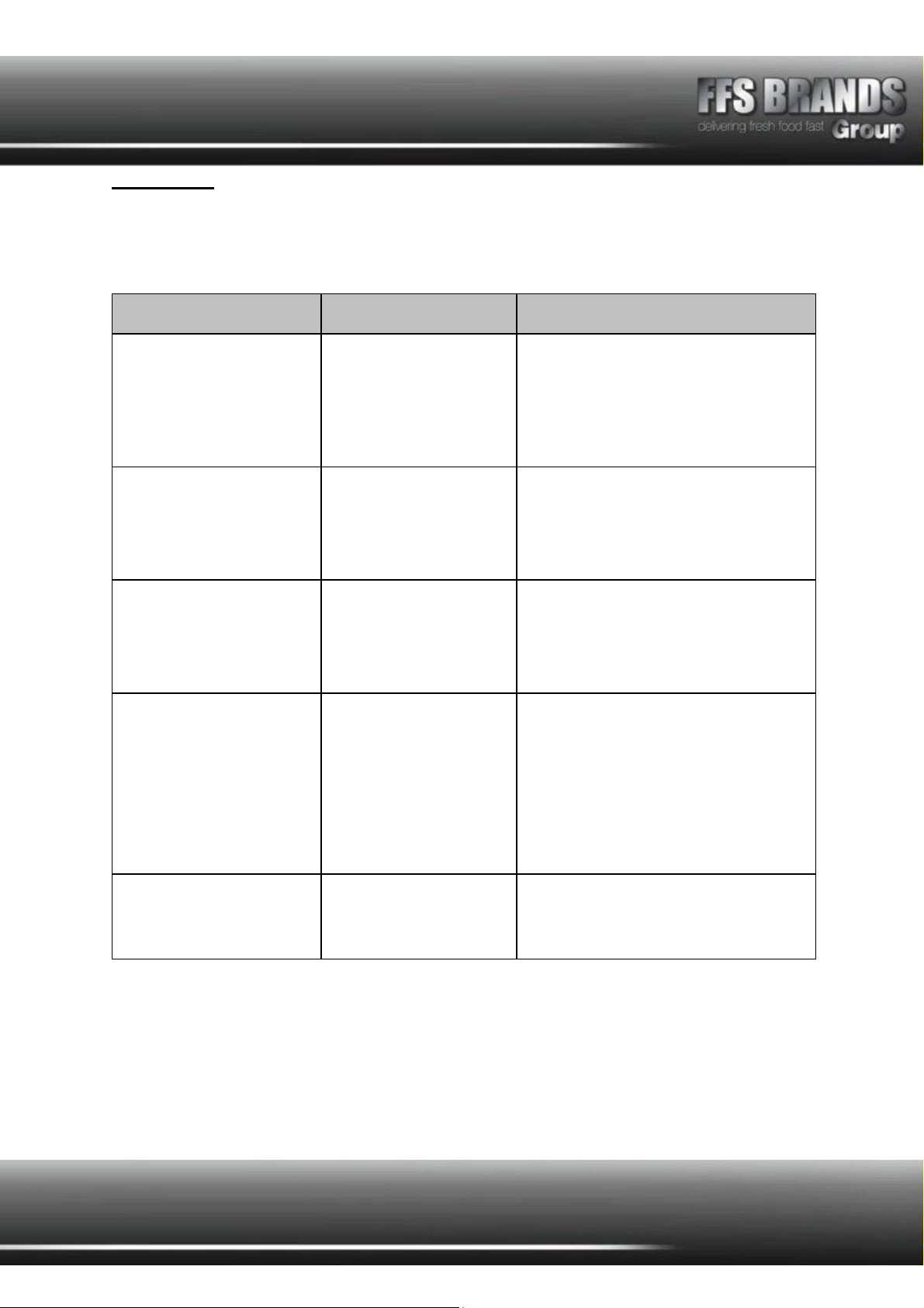
Faultfinder
Any servicing must be carried out by qualified personnel.
Disconnect from power before servicing.
Problem Possible Cause Solution
1. Rocker switch is not
illuminated.
No power to machine.
Rocker switch faulty.
Fuse faulty.
Check machine is plugged in & switched
ON.
Check supply trip/fuse. Reset/replace as
required.
Replace switch.
Check and replace if faulty.
2. Di
g
ital thermostat does not
illuminate
Rocker switch OFF.
Machine has over-
heated.
Digital controller
incorrectly set.
Digital controller faulty.
Switch ON. (See section1).
Allow to cool down.
Set correct temperature setting.
Replace digital controller.
3. Grid does not move. No power to machine.
Grid out of alignment
due to drive coupling
damage.
Drive motor capacitor
faulty.
Drive motor faulty.
See sections 1 and 2.
Realign or repair coupling (contact Fast
Food Systems.)
Replace drive motor capacitor.
Replace drive motor.
4. Grill does not heat up. No power to machine.
(HD4 only switching
relay faulty)
Thermocouple (probe)
faulty.
Digital controller faulty.
Element faulty
See sections 1&2.
Replace relay.
Replace thermocouple.
Replace controller (check parameters have
been correctly programmed.)
See section 1 and 2.
Replace element.
5. Grid does not move smoothly Drive component out of
alignment or damaged.
Drive motor/gearbox
damaged (1 part).
Have system corrected and realigned
(contact Fast Food Systems).
Have motor/gearbox replaced contact Fast
Food Systems.
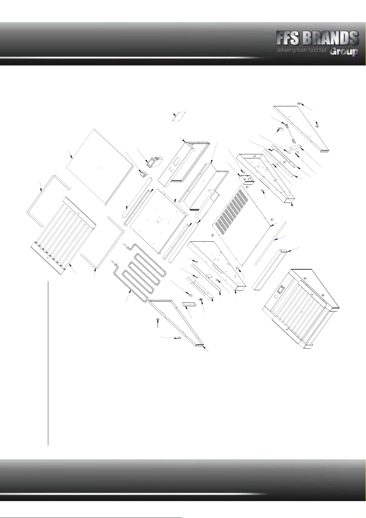
ASSEMBLED
05-07
05-07
EQVIHD2 HOT DOG GRILL 2
EXPLODED VIEW
05-01 COOKING PLATE
05-02 FRONT
05-03 REAR
05-04 BASE COVER
05-05 ELEMENT COVER
MFVC-14 RUNNER DOME
MFVO5-09T DRIVE BUSH
MFPLUGLEAD PLUG AND LEAD
MFVC-13 SNEEZE GUARD LOCATIONS
MFVC-25 ELEMENT
MFVC-07 DRIVE PIN
05-08
MFVC-14
MFVC-14
05-16
05-15
MFVC- 07
MFV05-24
MFV05-09T
MFV05-18
05-13
MFVC- 13
MFV12-25
MFV05- 09T MFVC-13
05-10
05-02
05-06
05-04
05-12
05-11
05-11
05-08
05-09
05-01
MFPLATE
05-03
MFVC- 14
MFVC- 14
05-12MFVC- 07
MF13701NAT
MFV05-24
05-16
05-15
MFVC-25
MFFF01
05-05
MFSTG61
LAELTR15 TIREAG
VISW17
MFVC-27MF05- 18
05-06 DRIVE BAR
05-07 ROLLER UNIT SURROUND BAR
05-08 INSULATOR STRIPS
05-09 ROLLER UNIT BAR
05-10 ELEMENT HOLDER
05-11 ELEMENT RETAINER
05-12 INTERNAL SIDE PANEL
05-13 SIDE PANEL
05-14 ROLLER GRID SIDE
05-15 RESIPRICATOR HOLDER
05-16 RESIPRICATOR
LAE LTR15TIREAG
DIGITAL THERMOSTAT
VISW17 SWITCH (RED)
MFV05-18 DRIVE LINK 1 (SMALL)
MFV12-25 DRIVE LINK 2 (LARGE)
MFV05-24 RESIPROCATOR WHEEL
MFFF01 FAST FOOT
MFVC-27 DRIVE SHAFT ASSEMBLY
MFSTG61 GEARBOX AND MOTOR
MF13701NAT SKIFFY PINS
MF PLATE SERIAL PLATE

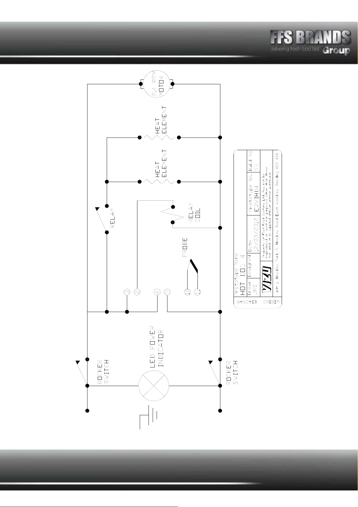
Wiring diagram HD2
Wiring diagram HD4
MFFF01
MFFF01 MFVC-07
MF13701NAT
MFV05-24
07-16
07-15
MFV05-09T MFVC-13
07-10
07-02
07-06
ASSEMBLED
07-07
07-01
EXPLODED VIEW
07-01 COOKING PLATE
07-02 FRONT
07-03 REAR
07-04 BASE COVER
07-05 ELEMENT COVER
07-06 DRIVE BAR
MFVC-07 DRIVE PIN
LAE LTR15 TIRE AG
VISW17 RED SWITCH
07-08 07-03
MFSTG61 MFVC- 14
MFVC-14
07-12
07-04
MFFF01
MFFF01
07-12
MFVC-14
MFVC-14
07-16
07-15
MFVC-07
MFV05-24
MFV05-09T
MFV12-25
07-13
MFVC- 13
MFVC- 25
MFVC- 25
07-07
07-09
07-08
07-11
07-11
MFPLATE
07-05
07-14
EQVIHD4 HOT DOG GRILL 4
LAELTR15 TIREAG
VISW17
MFVC-27
MF05- 25
MFV12-25
07-07 ROLLER UNIT SURROUND BAR
07-08 INSULATOR STRIPS
07-09 ROLLER UNIT BAR
07-10 ELEMENT HOLDER
07-11 ELEMENT RETAINER
07-12 INTERNAL SIDE PANEL
07-13 SIDE PANEL
07-14 ROLLER GRID SIDE
07-15 RESIPRICATOR HOLDER
07-16 RESIPRICATOR
MFV05-25 DRIVE LINK 1 (SMALL)
MFV12-25 DRIVE LINK 2 (LARGE)
MFV05-24 RESIPROCATOR WHEEL
MFFF01 FAST FOOT
MFVC-27 DRIVE SHAFT ASSEMBLY
MFSTG61 GEARBOX AND MOTOR
MF13701NAT SKIFFY PINS
MF PLATE SERIAL PLATE
MFVC-14 RUNNER DOME
MFVO5-09T DRIVE BUSH
MFPLUGLEAD PLUG AND LEAD
MFVC-13 SNEEZE GUARD LOCATIONS
MFVC-25 ELEMENT

Terms and Conditions
Claims
No claim shall be entertained by the Company unless made in writing. Claims arising from
damage or partial loss in transit must reach the Company within 7 days from the date of
delivery. Claims for non-delivery must reach the Company within 10 days from the date of
dispatch. All other claims must reach the Company within 7 days. Damaged goods must be
retained for inspection/collection.
Returns
The Company does not operate a returns policy unless the goods are defective:
In circumstances where the Company agrees to accept return of goods, a charge of 25% of
the invoice value will be made.

Damage claim form
Machine: HD2 VIHD2 / HD4 VIHD4
Product code: HD2 / HD4
Customer name……………………………………………………………
Date of delivery……………………………………………………………
Machine serial number…………………………………………………
Damage comments………………………………………………………
……………………………………………………………………………………………………………………………………
……………………………………………………………………………………………………………………………………
……………………………………………………………………………………………………………………………………
……………………………………………………………
Please indicate on the picture where the unit is damaged
Courier name…………………………………………………………………
Please cut this page out and post to
Fast Food Systems
(The address is on the back of this manual)
HD4
HD2

Warranty
UNITED KINGDOM AND REPUBLIC OF IRELAND
Excepting where otherwise specified all products are subject to 12 months parts and
labour warranty Goods found defective will be repaired, credited or replaced without
charge according to the terms of the Company’s standard warranty, provided written
notice is given within the guarantee period. In no case will the company be liable
for repairs made without its knowledge or sanction, or for indirect damage, or any
consequential loss or expense incurred by purchasers.
Fast Food Systems Ltd, warrants to the original purchaser that the equipment
supplied to be free from defective materials or workmanship for a period of 12
(twelve) months.
The following are NOT covered by warranty:
1. Failure or breakdown caused by incorrect installation.
2. Glass parts, electric lamps or door seals.
3. Adjustment or calibration of controls - this is a routine maintenance function.
4. Abuse or misuse, including cleaning.
5. Warranty labour is only carried out during normal working hours; calls
attended to out of hours may be subject to surcharges.
6. The warranty will commence either on installation or 1 (one) month from date
of dispatch - whichever is the sooner.
7. Warranty on spare parts purchased for equipment outside of the warranty
period is 3 (three) months from date of sale.
8. Any faulty spare parts replaced under warranty must be returned with 7 days
of supply.
9. Warranty is non-transferable.
Fast-Food-Systems Ltd
will not be held responsible, financially or otherwise, for
any loss of business as a result of equipment breakdown.
Fast Food Systems Limited
Manufacturer & Distributor of Catering Equipment
Unit 1 Headley Park 9 Headley Road East
Woodley Reading Berkshire RG5 4SQ
Tel: 0118 944 1100 Fax: 0118 944 0350
Email: service@fast-food-systems.co.uk
Website: www.fast-food-systems.com
ISSUE 22: 28th June 2017
Model Number………………………………
Order ID/Job No……………………………
Machine serial number……………………
Date of Manufacture ……/………/………
Date of delivery……/………/……
Date of Commissioning……/………/……
This manual suits for next models
1
Table of contents
Popular Grill manuals by other brands


Weber
Weber Skyline 3200 owner's manual

Vermont Castings
Vermont Castings Signature VCS3006 Assembly procedures

Renkforce
Renkforce IO-40TB ELA operating instructions

AMERICANA grill
AMERICANA grill 2010 user manual

Alice's Garden
Alice's Garden D'ARTAGNAN instruction manual

Blaze Outdoor Products
Blaze Outdoor Products BLZ-3NG Use & care guide


