21689_r03 3/13
BASE FUNCTION
FIRST LEVEL MENU
When the chronothermostat is connected to a
thermoregulation board, the following screen appears on
the display.
If the thermoregulation board is not compatible, you will
receive an error message.
In the figure the main screen. Above are shown the day of
the week and the current time, these indications are
intermittent if they are not updated.
Below there is an indication of the temperature measured
(measurement every 10 seconds);
Beside, an icon indicates the function of thermoregulation
currently active: in this case the image of a clock indicating
the automatic operation.
Corrispondence between icons and operation modes:
Automatic
Temperature control environment
according to the weekly program
set by the user.
Program seen as a graph of the
current day.
Domestic hot water operation
enabled.
Manual
Temperature control environment
in accordance with a user-selected
temperature (thermostat function).
Domestic hot water operation
enabled.
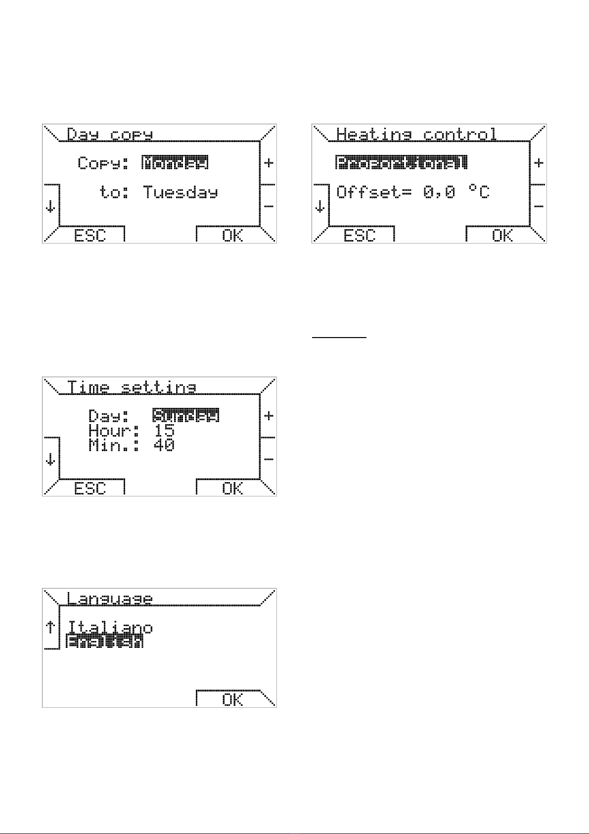
Vacation
Temperature control at a fixed
temperature for a number of days
set by the user.
Domestic hot water operation
enabled.
Summer
Temperature control environment
disable.
Summer ventilation can be
activated manually.
Domestic hot water operation
enabled.
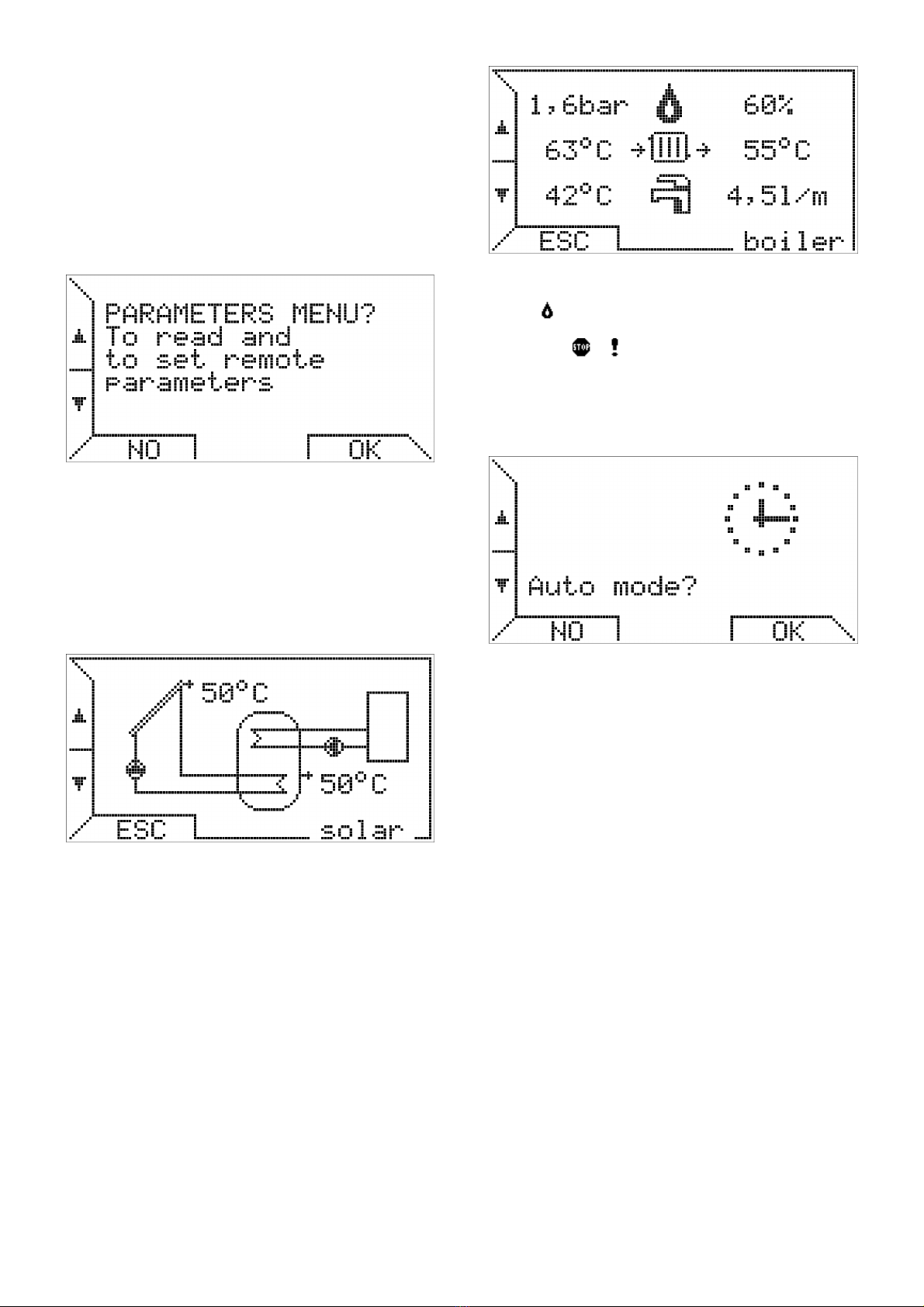
Standby
Temperature control environment
disable.
Demand hot water operation
disabled.
In “automatic mode”, the cronothermostat performs the
temperature control program was set for the current day,
the graph is visible at the bottom of the display.
The graph is divided into time intervals of 15 minutes,
corresponding to a pixel horizontally, and in the four
programmable temperature levels.
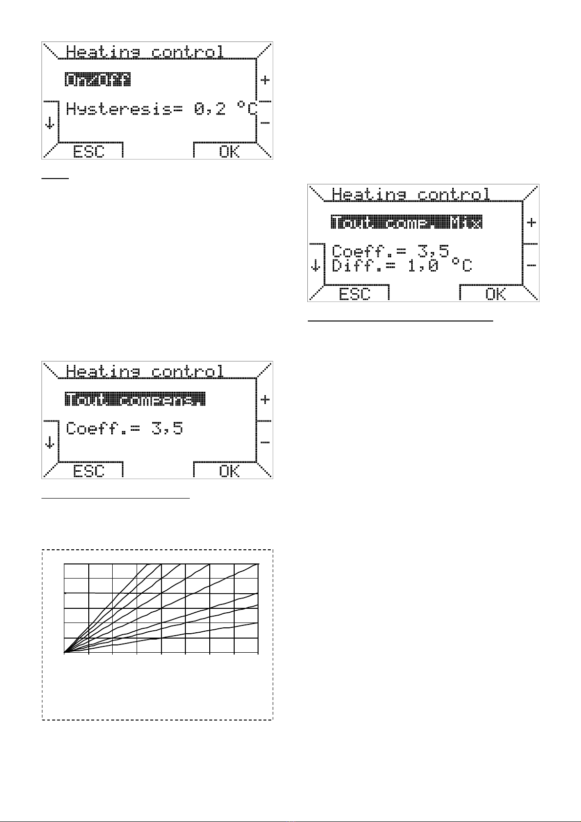
Near the icon of the operation mode other icons may
appear. If the boiler is turned on appears flame symbol,
different sizes depending on the modulation level of the
flame ( ). If it present a lockout or a fault appear
symbols ( , ) respectively and if it is not present the
connection icon appears symbol ( ). No icon appears in
the visualization if the boiler is in stand-by and has no
problem.
Under the indication of the ambient temperature may be
present, in addition, a line of text that provides information
to the user in special cases, such as the presence of error
or the status of additional functions such as management
of a system of solar panels integrated with the boiler and
managed by the thermoregulation board.
Here there are the messages that may appear, alongside
with their meanings:
Starting… OT11 is in the process of connection to the
boiler.
Modem connected OT11 correctly connected to the GSM modem.
Solare: standby Solar thermal system active and working correctly
in the standby state.
Solar: active Solar thermal system active and working correctly
with solar pump active.
Solar: boiler Solar thermal system active and working correctly,
integrated with the boiler.
Solar: disinf. Solar thermal system active and working correctly
with the tank disinfection procedure active.
Ambient probe error Room temperature sensor on OT11 damaged.
Solar: fault There is an anomaly in the solar thermal or part of
the boiler that manages the solar thermal system.
Modem error Communication error between OT11 and the
GSM modem
Fault code xxx There is an anomaly or a lockout on the boiler.
Code xxx .
Comm. error Communication error between OT11 and boiler.
Error ID xx The OT11 fails to correctly interpret of
information sent from the boiler.
Note: Please refer to the thermoregulation board's documentation for
detailed description of the fault codes and error codes.
The buttons on the right, marked with + and -, allow to vary
the temperatures required for the automatic program (T0,
T1, T2, T3). Instead, in “manual mode” (icon ) allow to
vary the corresponding temperature.
Pushing the buttons on the left, marked with arrows, you
can browse the pages of first level menu.
Pushing the button ▼, the following display appears.
Pushing the buttons +/- you can vary the temperature and
pushing the button you activate the “manual mode”.
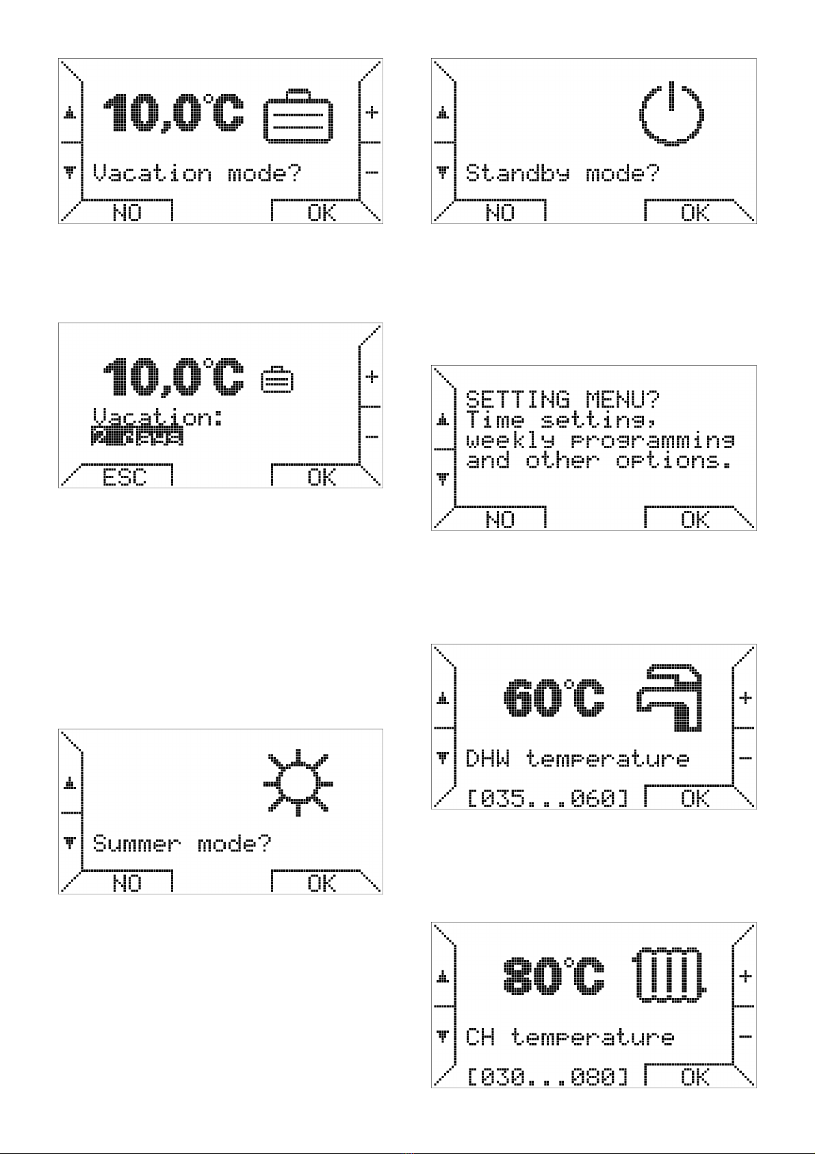
Another option selectable by the first level menu is the
“vacation mode”, which allows to maintain the desired
temperature for a configurable number of days, so as to
optimize power consumption in case of absence of the
users.