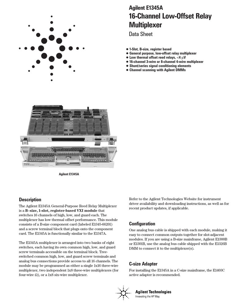
Fiberplex WDM16 User manual

USERMANUAL
ActiveWaveDivisionMultiplexer
WDM16/WDM8A/WDM8B


WarningforYourProtection
1.Readtheseinstructions.
2.Keeptheseinstructions.
3.Heedallwarnings.
4.Followallinstructions.
5.Donotusethisapparatusnearwater.
6.Cleanonlywithadrycloth.
7.Donotblockanyoftheventilationopenings.Installinaccordancewiththemanufacturer’sinstructions.
8.Donotinstallnearanyheatsourcessuchasradiators,heatregisters,stoves,orotherapparatus(includingamplifiers)thatproduceheat.
9.Donotdefeatthesafetypurposeofthepolarizedorgrounding‐typeplug.Apolarizedplughastwobladeswithonewiderthantheother.
Agroundingtypeplughastwobladesandathirdgroundingprong.Thewidebladeorthethirdprongisprovidedforyoursafety.Ifthe
providedplugdoesnotfitintoyouroutlet,consultanelectricianforreplacementoftheobsoleteoutlet.
10.Protectthepowercordfrombeingwalkedonorpinched,particularlyatplugs,conveniencereceptacles,andthepointwheretheyexit
fromtheapparatus.
11.Onlyuseattachments/accessoriesspecifiedbythemanufacturer.
12.Useonlywiththecart,stand,tripod,bracket,ortablespecifiedbythemanufacturer,orsoldwiththeapparatus.
Whenacartisused,usecautionwhenmovingthecart/apparatuscombinationtoavoidinjuryfromtip‐over.
13.Unplugthisapparatusduringlightningstormsorwhenunusedforlongperiodsoftime.
14.Referallservicingtoqualifiedservicepersonnel.Servicingisrequiredwhentheapparatushasbeendamagedin
anyway,suchaspower‐supplycordorplugisdamaged,liquidhasbeenspilledorobjectshavefallenintothe
apparatus,theapparatushasbeenexposedtorainormoisture,doesnotoperatenormally,orhasbeendropped.
Theapparatusshallnotbeexposedtodrippingorsplashing.Noobjectsfilledwithliquids,suchasvases,shallbeplacedontheapparatus.
“WARNING:Toreducetheriskoffireorelectricshock,donotexposethisapparatustorainormoisture.”
GeneralInstallationInstructions
Pleaseconsiderthesegeneralinstructionsinadditiontoanyproduct‐specificinstructionsinthe“Installation”chapterofthismanual.
Unpacking
Checktheequipmentforanytransportdamage.Iftheunitismechanicallydamaged,ifliquidshavebeenspilledorifobjectshavefalleninto
theunit,itmustnotbeconnectedtotheACpoweroutlet,oritmustbeimmediatelydisconnectedbyunpluggingthepowercable.Repair
mustonlybeperformedbytrainedpersonnelinaccordancewiththeapplicableregulations.
InstallationSite
Installtheunitinaplacewherethefollowingconditionsaremet:
Thetemperatureandtherelativehumidityoftheoperatingenvironmentmustbewithinthespecifiedlimitsduringoperationof
theunit.Valuesspecifiedareapplicabletotheairinletsoftheunit.
Condensationmaynotbepresentduringoperation.Iftheunitisinstalledinalocationsubjecttolargevariationsofambient
temperature(e.g.inanOB‐van),appropriateprecautionsmustbetaken.
Unobstructedairflowisessentialforproperoperation.Ventilationopeningsoftheunitareafunctionalpartofthedesignandmust
notbeobstructedinanywayduringoperation(e.g.‐byobjectsplaceduponthem,placementoftheunitonasoftsurface,or
improperinstallationoftheunitwithinarackorpieceoffurniture).
Theunitmustnotbeundulyexposedtoexternalheatsources(directsunlight,spotlights).

AmbientTemperature
UnitsandsystemsbyFiberPlexaregenerallydesignedforanambienttemperaturerange(i.e.temperatureoftheincomingair)of5°Cto40
°C(41°Fto104°F).Whenrackmountingtheunits,thefollowingfactsmustbeconsidered:
Thepermissibleambienttemperaturerangeforoperationofthesemiconductorcomponentsis0°Cto+70°C(32°Fto158°F)
(commercialtemperaturerangeforoperation).
Theairflowthroughtheinstallationmustallowexhaustairtoremaincoolerthan70°C(158°F)atalltimes.
Averagetemperatureincreaseofthecoolingairshallbeabout20°C(68°F),allowingforanadditionalmaximum10°Cincreaseat
thehottestcomponents.
Inordertodissipate1kWwiththispermissibleaveragetemperatureincrease,anairflowof2.65m³/minisrequired.
Example:ArackdissipatingP=800Wrequiresanairflowof0.8*2.65m³/minwhichcorrespondsto2.12m³/min.
Ifthecoolingfunctionoftheinstallationmustbemonitored(e.g.forfanfailureorilluminationwithspotlamps),theexhaustair
temperaturemustbemeasureddirectlyabovethemodulesatseveralplaceswithintheenclosure.
GroundingandPowerSupply
Groundingofunitswithmainssupply(ClassIequipment)isperformedviatheprotectiveearth(PE)conductorintegratedinthree‐pin
Phoenix™connector.Unitswithbatteryoperation(<60V,ClassIIIequipment)mustbeearthedseparately.Groundingtheunitisoneofthe
measuresforprotectionagainstelectricalshockhazard(dangerousbodycurrents).Hazardousvoltagemaynotonlybecausedbydefective
powersupplyinsulation,butmayalsobeintroducedbytheconnectedaudioorcontrolcables.
Thisequipmentmayrequiretheuseofadifferentlinecord,attachmentplug,orboth,dependingontheavailablepowersourceat
installation.Iftheattachmentplugneedstobechanged,referservicingtoqualifiedpersonnel.
ClassIEquipment(MainsOperation)
Shouldtheequipmentbedeliveredwithoutamatchingmainscable,thelattermustbepreparedbyatrainedpersonusingtheattached
femaleplug(Neutrik™powerCONTRUE1)withrespecttotheapplicableregulationsinyourcountry.
BeforeconnectingtheequipmenttotheACpoweroutlet,checkthatthelocallinevoltagematchestheequipmentrating(voltage,
frequency)withintheadmissibletolerance.Theequipmentfusesmustberatedinaccordancewiththespecificationsontheequipment.
Equipmentsuppliedwitha3‐poleapplianceinlet(protectionconformingtoclassIequipment)mustbeconnectedtoa3‐poleACpower
outletsothattheequipmentcabinetisconnectedtotheprotectiveearth.
WARNING:
Ifthegroundisdefeated,certainfaultconditionsintheunitorinthesystemtowhichitisconnectedcan
resultinfulllinevoltagebetweenchassisandearthground.Severeinjuryordeathcanthenresultifthe
chassisandearthgroundaretouchedsimultaneously.

Warranty,ServiceandTermsandConditionsofSale
ForinformationaboutWarrantyorServiceinformation,pleaseseeourpublished‘TermsandConditionsofSale’.Thisdocumentisavailable
onfiberplex.comorcanbeobtainedbyrequestingitfrom[email protected]orcalling301.604.0100.
Disposal
DisposalofPackingMaterials
Thepackingmaterialshavebeenselectedwithenvironmentalanddisposalissuesinmind.Allpackingmaterialcanberecycled.Recycling
packingsavesrawmaterialsandreducesthevolumeofwaste.Ifyouneedtodisposeofthetransportpackingmaterials,recyclingis
encouraged.
DisposalofUsedEquipment
Usedequipmentcontainsvaluablerawmaterialsaswellassubstancesthatmustbedisposedofprofessionally.Pleasedisposeofused
equipmentviaanauthorizedspecialistdealerorviathepublicwastedisposalsystem,ensuringanymaterialthatcanberecycledhasbeen.
Pleasetakecarethatyourusedequipmentcannotbeabused.Afterhavingdisconnectedyourusedequipmentfromthemainssupply,make
surethatthemainsconnectorandthemainscablearemadeuseless.
Disclaimer
Theinformationinthisdocumenthasbeencarefullycheckedandisbelievedtobeaccurateatthetimeofpublication.However,noliabilityis
assumedbyFiberPlexforinaccuracies,errors,oromissions,norforlossordamageresultingeitherdirectlyorindirectlyfromuseofthe
informationcontainedherein.

Introduction
TheFiberPlexWDMisan8or16ChannelWavelengthDivisionMultiplexer,witheachopticalchannelbroughtouttoanSFPslot,sotheuser
doesnotneedtosupplywavelength‐specificmodules.EachchannelcanbelinkedviafiberwithselectedFiberPlexFOMorFOIfibermodules,
FiberPlexLightViper™orwithvirtuallyanythirdpartyfiberopticequipmentwithdataratesfrom155megabitsupto3gigabitsperchannel,
forapossiblemaximumaggregatedatarateof48gigabits.
TheuserdataentersandleavestheWDMvia16SFPslotsontheWDM16,or8slotsontheWDM8AandWDM8B,whichcanbeleft
unpopulatedforunusedchannels,orpopulatedwithuser‐suppliedMSA‐compliantSFPmodulesthatareappropriatefortheuser’sdatarate,
protocolandjitterrequirements.Internally,theseconnecttofiberoptictransceiverswhicharetunedtothespecificwavelengthsforthe
channels,whicharethenmultiplexedontotheaggregatepairwhichconnecttotheotherWDM(s)inthelink.Datathatentersaspecific
channelononeWDMwillappearonthecorrespondingchannelontheotherWDM(s)inthelink,withnointerferencewithanyother
channels.
Possiblelinkconfigurationsare:
WDM16toWDM16–all16channelsthrough
WDM8AtoWDM8A–all8channelsthrough
WDM8BtoWDM8B–all8channelsthrough
TheaggregatefibersfromtheWDMunitsexitthechassisviaaduplexLCcoupler,whichconnecttosinglemodefiber,upto20kminlength.
Sincethisisanaggregatedwidebandstream,anyuserequipmentintheopticalpath(switches,couplers,etc.)mustbeabletoaccommodate
theentirebandwidthwithoutattenuation,andwillnotbeabletoreceiveordecodethestreamdigitally.
TheWDMunitshaveprovisionfortwo(2)powersupplymodulesforredundancyeachhavingcapacitytopowertheentireunit.AnACpower
inputmoduleisavailablenowandaDCversionisindevelopment;bothare‘hotswappable’.
KeyFeatures
16(or8)ChannelActiveWaveDivisionMultiplexer
Combines16(or8)opticalchannelsintoasinglefiberpair
Eachchannelindependentlysupportsdataratesfrom155MBupto3GB
SMPTEcompatibleinternalfiberoptics,videooptimizedtosupportPathologicalSignals
Eachopticchannelcanindependentlyacceptmultimodeorsinglemodeoptics,coaxconnectionorCAT5usingflexibleSFPmodules
Fullyredundant,hotswappablepowerforultimatereliability
WDMTheoryofOperation
Infraredlighthasafrequencyofapproximately400Terahertz(400,000Gigahertz).Thatisabout125,000timeshigherthanthedatarateofa
typical3GigabitSFP,whichmeansalargeproportionofthebandwidthofafiberopticcableiswasted.Thecurrentstateoftheartdoesnot
allowutilizingallofthatbandwidth,butwecanrecoversomeofitbyatechniquecalled“CoarseWaveDivisionMultiplexing,”or“CWDM.”
Essentially,itisthesimpletechniqueoftakingeach3Gigabitchannelandusingittomodulateadifferentfrequencyinthat400Terahertz
bandwidth.Thisisdonethroughaseriesofopticalfiltersandcombiners,alongwithlasersandphotodiodestunedtoaparticularinfrared
centerfrequency.Historically,however,opticsarereferredto,notbytheirfrequency,butbytheirwavelength,whichisthespeedoflight
dividedbythefrequency.
InthetraditionalimplementationofaCWDM,itistheuser’sresponsibilitytoprovidethetailoredSFPsandtheCWDMitself,whichmay
requireadapterstointerfacewiththeuserequipment.
TheFiberplexWDMline,ontheotherhand,isanactiveWDM,withthewavelength‐specificcomponentsalreadytestedandconfigured.
Insteadofawavelength‐specificopticalfiber,agenericSFPelectricalinterfaceisprovidedforeachchannel.AnySFPthatconformstothe
MSAcanbeinserted,evencopper‐basedSFPslikegigabitEthernet,SDI,HDMIorMADI.
TheinternalSFPshaveafull3Gigabitbandwidth,video‐optimized.GenericfiberSFPshavelimitationsinpassingvideosignals,sincetheydo
notmaintainaconstantDClevel.Thevideo‐optimizedSFPsareconstructedtobetterhandletheshiftingDClevelsinvideosignals.

PowerRedundancy
Inordertoremainfunctional,evenintheeventofcomponentfailures,theWDMemploysthefollowingredundancies:
Twopowersupplyslots,withloadequalizingandprotectioncircuitryonthebackplane.Eachsupplyhasthermalandovercurrent
protection.
Eachchannelhasitsownindependentpowersupplythatrunsoffofthemainpowerrails,sothatafailureinonechannelwillleave
theothersoperational.
Thereisamicroprocessorintheunit,butitsfunctionispurelymonitoring.Ifitfails,thedatawillcontinuetoflowunimpededonall
opticalchannels.
Therearetwoindependentfancontrolchannels,andtwocoolingfansoneachsideoftheunit.
DifferencesbetweenWDM16,WDM8AandWDM8B
ThefunctionalandphysicalcharacteristicsoftheWDM16,WDM8AandWDM8Barelargelyidentical.Thesingledifferentiatoristhenumber
ofActiveWaveDivisionchannelsandtheassociatedinternalwavelengthsthataresupported.Thechassisdimensionsandpowersupplies
remainidentical.
TheWDM16supportsallofthe16standardCWDMwavelengthsof1310‐1610nm,whereastheWDM8unitssupportonly8ofthose
channels,sotheinstallationcanbescaledtotheappropriatesize.TheWDM8Asupportstheupper8wavelengths1470‐1610nmandthe
WDM8Bsupportsthelower8wavelengths1310‐1450nm.BecauseoftheenormouslyflexibleactivenatureoftheWDM16/8,the
wavelengthsoftheinternalchannelsarebasicallyinvisibleandevenirrelevanttotheenduser.Thereasonstherearetwosubsetsof
wavelengthssupportedthroughtheWDM8AandWDM8Bisforfutureexpandabilityofthelineinprovidingthepossibilityofadd/drop,
combiningandsplittingcapability.
Whenonly8channelpointtopointfunctionalityisdesired,theWDM8Ashouldbethemodelofchoice.
ModelChannels InternalWavelengths
WDM16161310‐1610nm
WDM8A81470‐1610nm
WDM8B81310‐1450nm

GettingStarted
InitialInspection
Immediatelyuponreceipt,inspecttheshippingcontainerfordamage.Thecontainershouldberetaineduntiltheshipmenthasbeenchecked
forcompletenessandtheequipmenthasbeencheckedmechanicallyandelectrically.Iftheshipmentisincomplete,ifthereismechanical
damage,oriftheunitfailstooperatenotifyFiberPlexandmaketheshippingmaterialsavailableforthecarrier'sinspection.
ChassisMounting
Mountthechassisusingfastenersappropriatetoyourstandard19”rackenclosure.Allfour(4)mountingpointsMUSTbeutilized.Ensure
thatthereexistsadequateclearanceforfrontandrearventilation.Thechassisshouldbelocatedinanenvironmentwhereanambient
temperaturebetween0°and50°Ccanbemaintained.

FrontIndicators
1 2 3
Figure1WDM16FrontFace
Health–Multi‐functionindicatordisplayingoverallhealthoftheunit.Colorindicationscanbeinterpretedusingthefollowingtable:
LEDStateCondition
OffNopowertounit
RedOneormoreofthefollowinghaveoccurred:
Chassistemperatureisdangerouslyhigh–shutdown
theunitorincreasecoolingimmediatelytoprevent
damage
Bothcoolingfansarenotfunctioningproperly
Hardwarefailure/Self‐Checkfailure
YellowOneormoreofthefollowinghaveoccurred:
Chassistemperatureisatthehighendofthe
functionallimit–checkthattheairflowtemperatureis
withinlimitsandthatitisnotrestricted
Oneofthecoolingfansisnotfunctioningproperly
GreenTemperatureiswithinrange,fansareworkingproperlyand
theysystemisfunctioningnormally
PS1–ShowsstatusindicationofthepowersupplyinPSSlot1(topslot).Colorindicationscanbeinterpretedusingthefollowingtable:
LEDStateCondition
OffNopowersupplyinstalled
RedOneormoreofthefollowinghaveoccurred:
Powersupplytemperatureisdangerouslyhigh–shut
downtheunitorincreasecoolingimmediatelyto
preventdamage
Inputpowerispresentbutoutputisoutofrange–
replacethepowersupply
YellowOneormoreofthefollowinghaveoccurred:
Powersupplytemperatureisatthehighendofthe
functionallimitlimit–checkthattheairflow
temperatureiswithinlimitsandthatitisnotrestricted
Noinputpowerispresent–checktheACsupply
Communicationtochassiscannotbeestablished–
replacethesupply
GreenTemperatureiswithinrangeandthepowersupplyis
functioningnormally
PS2–ShowsstatusindicationofthepowersupplyinPSSlot2(bottomslot).Colorindicationscanbeinterpretedusingthetableabove.

RearIndicators/Connections
108
4 5 76
9
Figure2WDM16RearPanel(shownwithoptionalredundantpowersupply)
4 5 7
108
6
9
Figure3WDM8ARearPanel(shownwithoptionalredundantpowersupply)
PowerSupplySlots–AtleastonePSMACmustbeinstalledinaslotfortheunittooperate.ThetopslotisdesignatedPS1andthe
bottomslotisPS2.Forfullredundancy,powersuppliescanbeinstalledinbothslots.Theseslotssupport‘hotswapping’ofthesupplies.
TXFaultRXDetect–ThereisonepairoftheseLEDindicatorsassociatedwitheachSFPslotontheunit.Theycorrespondtotheslot
directlybelow.Colorindicationscanbeinterpretedusingthefollowingtable:
TXFaultRXDetectSFPInstalled TransmitterFunctioning* ReceiveSignalPresent*
OffOffNon/an/a
RedRedYesNoNo
RedGreenYesNoYes
GreenRedYesYesNo
GreenGreenYesYesYes
*NotethatsomecopperEthernetandVideoSFPsmayhavecustomTXFaultandRXDetectimplementations.SeeSFPdocumentationofindividualSFPformoreinformation.
SFPSlot–InstallSFPsinthisslot.TheseslotsconformtotheSFPMSA(INF‐8074imoreinformationlaterinthismanual).Theyarefixed
bi‐directionalportsandcannotsupportdualTXordualRXSFPs.AnystandardMSAcomplaintSFPcanbeusedintheseslotsincluding
butnotlimitedtoopticalmoduleswithdataratesintherangeof155Mbpsto3.0Gbps,Ethernetcoppermodules,videocopper
modules,copperquadraxSFPtoSFPcables,etc.
EachchannelisindependentandwillacceptanyformatandanyMSAcompliantusersuppliedSFPmodulethatisappropriateforthe
user’sequipment.Above500Mbps,ultra‐lowjitterSFP’sarerecommended(40psec.)aswellasITU‐TG.652.D/IEC60793‐2‐50.B1.3
compliantfiberopticcable.
AggregateFiberConnection–ANeutrik™opticalCONDUOconnectorprovidesabi‐directionalsinglemodefiberinterfacetothe
aggregatedI/OoftheCWDM.Thisopticalsignalcarriesthedatausingall16(8)wavelengthsinternallyallocatedtothe16(8)external
SFPcages.Thisopticalsignalisnotcompatiblewithsinglewavelengthpassiveoractiveopticaldevices.TheopticalCONDUOprovides
forbothatacticalconnectionsusingamatingopticalCONDUOcableorastandardconnectionwithLCterminations.
Health–ThisindicatorservesthesamefunctionastheHealthindicatoronthefrontpanelexceptitdoesnotreporttheyellow
condition.

FAC(FiberPlexAuxiliaryControl)–DualRJ11connectionsprovideanRS422connectionforaccessingreportingandcontrolinformation
fromtheWDM16/8.Thisisadaisychainedbussallowingtheconnectionofmultipleunitswithonecontrolcomputer.Theuseofthis
portisdescribedinmoredetaillaterinthismanual.
11 12 13
Figure4PSMACPowerSupplyModule
ACInlet–PowerisprovidedthroughaNeutrik™powerCONTRUE1connector.Connectto100‐240VACpowersourceusingthesupplied
ACpowercord.
FuseCompartment–Containsthefuseforthepowersupply.Thefusecompartmentcapcanbetwistedoffusingaflathead
screwdriverandthefuseremoved.Replacefusewitha2Atime‐delayfuse(Littlefusemodel218.002Slo‐Blo).Additionalinformationis
laterinthismanual.
StatusIndicator–HasthesamefunctionasPS1 andPS2 onthefrontpanelasdescribedearlierinthissection.

PowerRequirements&PSMMounting
Thepowersupplymodules(PSMAC)acceptvoltagesfrom100‐240VAC,50/60Hz.Maximumpowerconsumptionis100Wpermodule.
Althoughthepowersupplymodulesaredesignedtobehotswappable,itisoptimalpracticetoinsertamoduleintothechassispriortothe
applicationofACpower.Thepowersuppliesmustbeinstalledinthetopmostslotwhenviewingtheinsertionendof
therespectivemodelchassis.Asecondaryredundantpowersupplymaybeinstalledinthebottomslot.
Toaccessthefuses,disconnectpowercord,andremovethepowersupplyunitfromthechassis.Replacementfusesmusthavetherequired
currentratingandmustbeofthespecifiedtype.Useofrepairedfusesand/orbypassofthefuseholdersisnotrecommendedandwillvoid
thewarranty.
Thesystempowerrequirementfora17‐unit(maximum)rackconfigurationis115VAC@15Amps;ifsuppliedwith230VAC,8Ampsis
required.
Figure5InsertingPowerSupply
UsingRedundantPowerSupplies
TheWDM16/8unitscomestandardwithasinglePSMACpowersupplyinstalled.Thisconfigurationmaybeperfectlyacceptableformany
applications.Inthecaseofmissioncriticalapplicationswhichhavezerotolerancefordowntime,itisadvisabletoaddasecondoptional
PSMACpowersupplyforcompleteredundancy.Thesecondsupplycanbeinsertedatanytimeintheunusedpowersupplyslot.Insertthe
supplyfirst,thenapplyexternalACpower.
ThePSMACandtheWDM16/8support‘hotswapping’ofthepowersupplies.Thismeansthateithersupplycanberemovedorinserted
withoutpoweringdowntheunit.Withtwosuppliesinstalled,intheeventofafailureofonePSMAC,theunitwillcontinuetooperateonthe
remainingsupply.Anewreplacementcanbeinstalledandpoweredupwithoutdisturbingtheunit.
Bestpracticeforutilizingredundantpoweristoconnecteachsupplytoadifferentpowersourceor‘phase’ofpower.Thiswayifonephase
ofpowersuffersanoutage,theunitwillcontinuetoworkontheremainingphase.
PowerSupplyModuleFuseReplacement
Thepowersupplymodulesareeachprotectedbyasingle2Atime‐delayfuse(Littlefusemodel218.002Slo‐Blo).Replacementofthefuse
requiresthepowercordtobedisconnectedfromthepowersupplyACinletandthepowersupplytoberemovedfromthechassis.Toaccess
thefuse,useanappropriatesizedflatheadscrewdriverandremovetheFuseCompartmentCap.ThefusewillsimplyslideoutoftheFuse
Compartmentwiththecapremoved.SlideanewfusewhichmeetsthestatedspecificationsintotheFuseCompartmentandreplacethecap.
Youmaynowre‐insertthepowersupplyintothechassisandreconnectthepowercordtothepowersupplyACinletconnector.
Replaceonlywithidenticalorequivalenttime‐delayfuse.

REMOVE CAP, REPLACE FUSE
(
SCREWDRIVER SL
O
T
)
Figure6ReplacingtheFuseinthePSMAC

InsertingandRemovingSFPModules
IdentifytheLatchTypeoftheSFPModule
SFPModuleshavevariouslatchingmechanismstosecurethemintotheSFPCageofadevice.TheFiberPlexWDMcansupportahostof
manufacturersandbrandsofSFPModulessotheusermayencounteranynumberofdifferentlatches.Someofthesearedescribedbelow.
BailClasp
ThebailclaspSFPmodulehasaclaspthatyouusetoremoveor
installtheSFPmodule.
ActuatorButton
TheactuatorbuttonSFPmoduleincludesabuttonthatyoupushin
ordertoremovetheSFPmodulefromaport.Thisbuttoncaneither
lift‘Up’orpress‘In’toreleasetheSFPModuledependingonthe
manufacturer.
MylarTab
TheMylartabSFPmodulehasatabthatyoupulltoremovethe
modulefromaport.
SlideTab
TheslidetabSFPmodulehasatabunderneaththefrontoftheSFP
modulethatyouusetodisengagethemodulefromaport.
InsertingaModule
1) AttachanESD‐preventativewristoranklestrap,followingitsinstructionsfor
use.
2) DisconnectandremoveallinterfacecablesfromSFPModule.
3) IftheSFPModulehasaBailClasp,closetheBailClaspbeforeinsertingthe
SFPModule.
4) Withthegoldfingerconnectoronthebottomandthelabelonthetop,lineup
theSFPModulewiththeemptycageandslideitinmakingsurethatitis
completelyinsertedandseatedinthecage.
HandlingWarnings
SFPModulesarestaticsensitive.Topreventdamagefromelectrostaticdischarge(ESD),itisrecommendedtoattachanESD
preventativewriststraptoyourwristandtoabaremetalsurfacewhenyouinstallorremoveanSFPModule.
DisconnectallopticalorcoppercablesfromSFPModulespriortoinstallingorremovingtheSFPModule.Failuretodosocould
resultindamagetothecable,cableconnectorortheSFPModuleitself.RemovingandinsertinganSFPModulecanshortenits
usefullife,soyoushouldnotremoveandinsertSFPModulesanymoreoftenthanisabsolutelynecessary.
ProtectopticalSFPmodulesbyinsertingcleandustcoversintothemafterthecablesareremoved.Besuretocleantheoptic
surfacesofthefibercablesbeforeyouplugthembackintotheopticalportsofanotherSFPmodule.Avoidgettingdustandother
contaminantsintotheo
p
tical
p
ortsof
y
ourSFPmodules
,
becausetheo
p
ticswillnotworkcorrectl
y
whenobstructedwithdust.

RemovingaModule
1) AttachanESD‐preventativewristoranklestrap,followingitsinstructionsforuse.
2) DisconnectandremoveallinterfacecablesfromSFPModule.
3) Releasethelatchingmechanism.
BailClasp–OpenthebailclaspontheSFPModulewithyourfingerinadownwarddirection.
ActuatorButton–Gentlypresstheactuatorup(orin)whilepullingthebodyoftheSFPModuletoreleasetheSFP
Modulefromthecage.
A
ctuator Button
MylarTab–Pullthetabgentlyinastraightoutwardmotionuntilitdisengagesfromthe
port.Makesurethetabisnottwistedwhenpullingasitmaybecomedisconnectedfrom
theSFPModule.
SlideTab‐Withyourthumb,pushtheslidetabonthebottomfrontoftheSFPmodulein
thedirectionoftheequipmenttodisengagethemodulefromthelinecardport.Ifyou
pullontheSFPmodulewithoutdisengagingthetab,youcandamagetheSFPmodule.
4) GrasptheSFPModulebetweenyourthumbandindexfingerandcarefullyremoveitfromtheport
5) PlacetheSFPModuleonanantistaticmat,orimmediatelyplaceitinastaticshieldingbagorcontainer

ConnectingAggregateFiberConnection
ANeutrik™opticalCONDUOconnectorprovidesabi‐directionalsinglemodefiberinterfacetotheaggregatedI/OoftheCWDM.Thisoptical
signalcarriesthedatausingall16(8)wavelengthsinternallyallocatedtothe16(8)externalSFPcages.Duetoitsbroadwavelengthcontent,
thisopticalsignalisnotcompatiblewithsinglewavelengthpassiveoractiveopticaldevicessuchaspassivesplitter,opticaltransceiver
modules,etc.TheopticalCONDUOprovidesforbothatacticalconnectionusingamatingopticalCONDUOcableorastandardconnection
withLCterminations.
MakingaTacticalConnection
AtacticalfiberconnectioncanbeachievedbysimplyutilizingaNeutrik™opticalCONDUOfibercableassemblyfortheaggregatefiberrun.
TheopticalCONcableconnectorwillsimply‘push’intoplace.Disconnectingthecablerequiresgraspingthecableconnectorwithyourfull
handandpullingbackthereleaseringwithyourthumbandforefingerwhilepullingtheconnectorstraightout.SeeNeutrik™documentation
formoreinformation.
MakingaStandardLCConnection
StandardsinglmodeLCconnectionscanbemadebysimplypluggingtheLCcableconnectorsdirectlyintotheNeutrik™opticalCONconnector
ontheWDM16(8).Whenlookingattheaggregateconnectorfromtherear,theTransmit(TX)willbetheLCconnectorontheleftlabeled‘A’
andtheReceive(RX)willbeontherightlabeled‘B’.Forclarificationpurposes,‘Transmit(TX)’meanslightwillbeemittedfromthisconnector
and‘Receive(RX)’meansthatlightisexpectedtotravelintotheconnector.
RX
TX
Figure7Neutrik™opticalCONDUOconnector
MakingOtherFiberConnections
OthersortsofsinglemodefiberconnectionscanbesupportedthroughtheuseofLCjumpers(notincluded).Forexample,STfiber
connectionscanbesupportedbyusingLCtoSTfiberjumpercablesandSTbarrelconnectors.

OtherConsiderations
FiberPlexAuxiliaryControl(FAC)Interface
Ontherearoftheunit,neartheopticalCONDUOconnector,aretwoRJ‐11jacks,onemarked“In”andtheother,“Thru.”Thesesupporta
proprietary,115.2kBaudRS‐422serialprotocolthatenablesacontrollingdevicetopollthestatusofconnecteddevices.Upto255unitscan
bedaisy‐chainedononelink,withthe“In”astheupstreamlink(eventuallyleadingtothecontroller)andthe“Thru”asthedownstreamlink.
Figure8FACControlontherearoftheWDM16
Thepinoutsoftheconnectorsareasfollows:
ConnectorPinFunction
1Rx+(totheWDM)
2RX–(totheWDM)
3TX–(fromtheWDM)
4TX+(fromtheWDM)
AstandardcrossoverRJ11cablecanbeusedtodaisychainunitstogether.
FortheWDM,thefollowinginformationcanbeaccessed:
Temperatureofthelogicboardandpowersupplies
Channelstatus(SFPinserted,signalpresent,transmitgood)
IdentificationofSFPmodelsandmanufacturer
Statusofcoolingfans,includinglevelandoperationalstatus
PowersupplyVoltages,temperaturesandswitchingfrequency
AnexampleapplicationavailablefromFiberPlexappearsasfollows:
ContactFiberPlexformoreinformationastoavailabilityofthisandotherapplications.

VideoOptimization
TheSocietyofMotionPictureandTelevisionEngineers,orSMPTE,isaleaderinthedevelopmentofstandardsforfilm,television,andother
video.TheSerialDigitalInterfaceorSDI,wasstandardizedbySMPTEforbroadcastqualitydigitalvideotransmission.Otherstandards
evolvedfromthisoriginalstandard,definingEnhanced,High‐definition(HD),3G‐SDI(1080p)andUltraHigh‐definition(UHD),or4Kvideo
(2160p).
Tohelpensureerror‐freetransmission,thestandardsincludeadatascrambler/descramblertocreateahighdensityoftransitionsinthe
serialdata,makingiteasierforthereceivertomaintaintiming.Whereanencodingmethodsuchas8B‐10Bensuresaminimalsequentialrun
ofallonesorzeros,itdoessoatthecostofa25%increaseinbandwidthrequirements.Thescrambler/descramblermethoddoesnot
requirethis,butasaresulttherearecertaincombinationsofscramblerstateandthenextdatabitstobescrambledthatresultinasequence
ofuptotwentyconsecutiveonesorzeros.Thesesequencesarereferredtoaspathologicalconditions,andarepresentinspecificshadesof
pinkorgrey.
ThesepathologicalconditionsmaycreateerrorsintransmissionthroughtypicalACcoupledoptics,oranyotherACcoupledinterface.Video
EnhancedorSMPTECompliantopticsaredesignedtoacceptthesepathologicalconditions,allowingthelongersequencesofonesorzerosto
passwithouterror.
TheFiberplexTechnologiesWDM16andWDM8ActiveCoarseWaveDivisionMultiplexerhasVideoEnhancedopticspre‐installedinternally
oneveryport,ensuringerror‐freetransmissionforallofyourvideorequirements.
SFPMSACompliance
TheSFPMulti‐SourceAgreement(MSA)isanagreementthatwasdraftedamongcompetingmanufacturersofSFPopticalmodules.TheSFF
CommitteewasformedtooverseethecreationandmaintenanceoftheseagreementsincludingtheSFPMSAdesignatedasINF‐8074i.This
agreementdescribesamutuallyagreeduponstandardfortheformandfunctionofSFPmodules.However,notallSFPsproducedareMSA
compliant.TheMSAprovidesforatransceiver(TX/RX)pinout.OtherindustriessuchasbroadcasthadtheneedfordualTXanddualRXSFP
foruni‐directionalapplicationssuchasvideo.Naturally,anon‐MSAstandardwasintroducedallocatingpinoutassignmentsfordualoutput
anddualinputI/Oconfigurations.Inaddition,thesomeoftheinternalserialcommunicationpinswerereassigned.
TheuniquedesignoftheWDM16/8includesinternalmulti‐rate,CWDMopticalSFPswhichhandlethewavelengthallocationoftheCWDM.
TheseinternalmodulesareMSAcompliant,thustheexternaluseraccessibleSFPmodulesmustalsobeMSAcompatible.Forthisreasonyou
cannotusenon‐MSASFPswiththeWDM16/8.
BesurethatanySFPsthatyouwishtousewiththisunitconformtothepinoutinFigure9.
Figure9PinoutofSFPcageonWDM16/8


WDM16Specifications
19
.
00
[482.6]
3.00
[76.2]
3
.
4
7
[88.1]
18.33
[465.5]
.25
[6.4]
17.25
[
4
38.2
]
13.12
[333.2]
13.62
[346.0]
Figure10WDM16/8OverallDimensions
This manual suits for next models
2
Table of contents
Popular Multiplexer manuals by other brands

Vetra
Vetra TouchMux VIP- 884-V Series User instruction

NEO
NEO AVM-3901-B Installation and operation manual
metraTec
metraTec hfMux-X Technical documentation
Panasonic
Panasonic WJ-FS616C operating instructions
ADTRAN
ADTRAN Total Access 3000 Installation and Maintenance

Pickering
Pickering PCI 50-670 user manual
