FOR-A UFM-3MUXAI User manual

OPERATION
MANUAL
UFM-30MUX
3G/HD/SD Digital Audio Multiplexer
UFM-3MUXAI
1st Edition - Rev. 2
USO RESTRITO

2
Edition Revision History
Edit.
Rev.
Date
Description
Section/Page
1
-
2013/03/29
First Edition
1
1
2013/04/30
Added "Operation Examples"
Corrected factual errors.
Sec. 5
1
2
2013/08/27
Added "no signal" indication in SDI AUDIO IN SYNC
Added "no signal" indication in SDI AUDIO IN PCM
Added "no signal" indication in AES IN SYNC
Added "no signal" indication in AES AUDIO IN PCM
Spec details added to Audio Input (SDI embedded,
AES/EBU) and Audio Output (SDI embedded)
UFM-30MUX power current changed
Sec. 6-6-4
Sec. 6-6-5
Sec. 6-6-8
Sec. 6-6-9
Sec. 10-1-1
Sec. 10-1-1
USO RESTRITO

3
Precautions
Important Safety Warnings
[Power]
[Circuitry Access]
Stop
Do not touch any parts / circuitry with a high heatfactor.
Capacitors can retain enough electric charge to cause mild to serious shock, even
after power is disconnected. Capacitors associated with the power supply are
especially hazardous. Avoid contact with anycapacitors.
Hazard
Unit should not be operated or stored with cover, panels, and / or casing removed.
Operating unit with circuitry exposed could result in electric shock / fire hazards or
unit malfunction.
[Potential Hazards]
[Consumables]
The consumables used in unit must be replaced periodically. For further details on
which parts are consumables and when they should be replaced, refer to the
specifications at the end of the Operation Manual. Since the service life of the
consumables varies greatly depending on the environment in which they are used,
Caution they should be replaced at an early date. For details on replacing the consumables,
contact your dealer.
If abnormal smells or noises are noticed coming from the unit, turn power off
immediately and disconnect power cord to avoid potentially hazardous conditions. If
problems similar to above occur, contact authorized service representative before
Caution attempting to again operate unit.
Stop
Do not place or drop heavy or sharp-edged objects on powercord. A damagedcord
can cause fire or electrical shock hazards. Regularly check power cord for
excessive wear or damage to avoid possible fire / electrical hazards.
USO RESTRITO

4
Upon Receipt
Unpacking
UFM-30MUX Digital Audio Multiplexer modules are fully inspected and adjusted prior to
shipment. Operation can be performed immediately upon completing all required connections
and operational settings.
Check your received items against the packing lists below. Check to ensure no damage has
occurred during shipment. If damage has occurred, or items are missing, inform your supplier
immediately.
UFM-30MUX box
ITEM
QTY
REMARKS
UFM-30MUX
1 set
Front module 1
Rear module 1
Operation Manual
1
(This manual)
UFM-3MUXAI box (Analog Input Option)
ITEM
QTY
REMARKS
UFM-3MUXAI
1 set
Front module 1
Rear module 1
Flat cable
1
For connection to UFM-30MUX
Gasket
1
For attachment to UFM-30MUX
UFM-30MUX and UFM-3MUXAI modules are used by installing them into a UF-106B or
UF-112 UFM Frame.
UF-106B supports up to 6 pairs of modules (Up to 4 pairs if UF-106BPS isinstalled)
UF-112 supports up to 12 pairs of modules.
Remote Control Options
ITEM
REMARKS
UFM-30CTL
Control Card
USO RESTRITO

5
Table of Contents
1. Prior to Starting........................................................................................................................... 7
1-1.Welcome.............................................................................................................................. 7
1-2. Features .............................................................................................................................. 7
1-3. About This Manual .............................................................................................................. 7
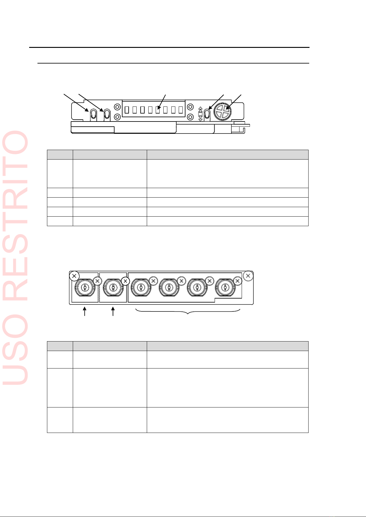
2. Panel Descriptions...................................................................................................................... 8
2-1. UFM-30MUX........................................................................................................................ 8
2-2. UFM-3MUXAI (Option)........................................................................................................ 9
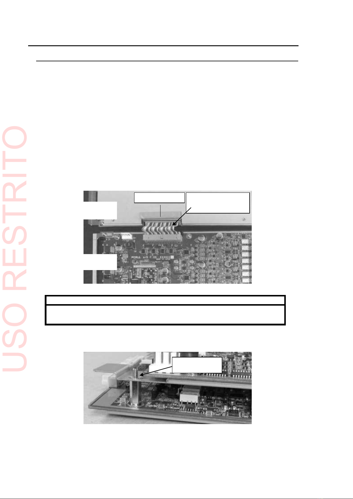
3. Connection.................................................................................................................................10
3-1. Installing to a UFM frame...................................................................................................10
3-2. Basic Configuration (UFM-30MUX)....................................................................................12
3-3. Optional Configuration (UFM-3MUXAI) .............................................................................12
3-3-1. Analog Audio Connection............................................................................................12
4. Operation...................................................................................................................................14
4-1. Power ON...........................................................................................................................14
4-2. Operation and Menu Modes...............................................................................................14
4-2-1. Operation (Normal) Mode ...........................................................................................14
4-2-2. Menu Mode .................................................................................................................15
4-2-3. Menu Operation Example ...........................................................................................16
4-3. Menu List............................................................................................................................18
5. Operation Examples..................................................................................................................21
5-1. AES CH1-4 >> SDI EMB CH1-4........................................................................................21
5-2. SDI EMB GRP1 >> SDI EMB GRP2..................................................................................22
5-3. Synchronous / Asynchronous Audio Mapping...................................................................23
6. Menu Details..............................................................................................................................24
6-1. Input Menu..........................................................................................................................24
6-1-1. SDI IN SYNC MODE...................................................................................................24
6-1-2. AES IN SYNC MODE..................................................................................................24
6-1-3. SDI IN PCM MODE/AES IN PCM MODE ................................................................24
6-1-4. ANALOG INPUT LEVEL.............................................................................................25
6-1-5. SDI IN GAIN/AES IN GAIN/ANALOG GAIN..........................................................25
6-2. Mapping Menu....................................................................................................................25
6-2-1. SDI OUT MAPPING....................................................................................................25
6-3. Output Menu.......................................................................................................................26
6-3-1. EMB THRU..................................................................................................................26
6-3-2. SDI OUT STEREO MODE..........................................................................................26
6-3-3. SDI OUT RESOLUTION.............................................................................................26
6-3-4. SDI OUT GAIN............................................................................................................26
6-4. LTC Menu...........................................................................................................................27
6-4-1. LTC MUX.....................................................................................................................27
6-4-2. LTC SEL......................................................................................................................27
6-5. System Menu......................................................................................................................27
6-5-1. SDI BYPASS...............................................................................................................27
6-5-2. SDI LOCK MODE........................................................................................................27
6-5-3. TV SYSTEM................................................................................................................28
USO RESTRITO

6
6-5-4. MINIMUM DELAY.......................................................................................................28
6-5-5. REF LEVEL.................................................................................................................28
6-5-6. TEST MODE...............................................................................................................28
6-5-7. FACTORY SET...........................................................................................................28
6-6. Status Menu (Display only)................................................................................................29
6-6-1. SDI STATUS...............................................................................................................29
6-6-2. SDI TV SYSTEM.........................................................................................................29
6-6-3. SDI AUDIO IN ON/OFF ..............................................................................................29
6-6-4. SDI AUDIO IN SYNC..................................................................................................29
6-6-5. SDI AUDIO IN PCM....................................................................................................29
6-6-6. LTC IN ON/OFF..........................................................................................................29
6-6-7. AES IN ON/OFF..........................................................................................................30
6-6-8. AES IN SYNC .............................................................................................................30
6-6-9. AES AUDIO IN PCM...................................................................................................30
6-6-10. SLOT.........................................................................................................................30
6-6-11. OPTION ....................................................................................................................30
6-6-12. VERSION..................................................................................................................30
7. Workflow Block Diagrams .........................................................................................................31
7-1. AUDIO Processing.............................................................................................................31
7-2. TIME CODE Processing ....................................................................................................31
7-3. MINIMUM DELAY..............................................................................................................32
8. UFM-3MUXAI Card Settings.....................................................................................................33
8-1. UFM-3MUXAI FRONT CARD............................................................................................33
8-2. Digital Output Level versus Analog Input Level.................................................................34
9. Troubleshooting.........................................................................................................................35
10. Specifications and Dimensions...............................................................................................36
10-1. Specifications...................................................................................................................36
10-1-1. UFM-30MUX.............................................................................................................36
10-1-2. UFM-3MUXAI............................................................................................................37
10-2. External Dimensions........................................................................................................38
10-2-1. UFM-30MUX.............................................................................................................38
10-2-2. UFM-3MUXAI............................................................................................................39
USO RESTRITO

7
1. Prior to Starting
1-1. Welcome
Congratulations! By purchasing UFM-30MUX Digital Audio Multiplexer modules you have
entered the world of FOR-A and its many innovative products. Thank you for your patronage and
we hope you will turn to FOR-A products again and again to satisfy your video and audio needs.
FOR-A provides a wide range of products, from basic support units to complex system
controllers,which have been increasingly joined byproducts for computer video-based systems.
Whatever your needs, talk to your FOR-A representative.We will do our best to be of continuing
service to you.
The UFM-30MUX, Digital Audio Multiplexer plug-in module is installed into a UF-106B or
UF-112 UFM Frame. The unit accepts 3G/HD/SD-SDI signal input and 8-ch
AES/EBU audio input and multiplexes the video and audio signals into an SDI
output. The AES 7/8 input port can also accept LTC signal by changing the switch
setting on the front panel. LTC input can be also embedded into the SDIoutput.
The UFM-3MUXAI optional analog input module for the UFM-30MUX is also installed into the
UFM frame. The unit converts analog input audio (4 stereo pairs) to digital audio
signals and embeds them into the SDI output stream from theUFM-30MUX.
1-2. Features
Accepts an SDI stream and 4-pair (8ch) AES/EBU input and outputs the signal as an SDI
stream.
Supports 3G/HD/SD-SDI.
Maximum 32 ch audio source: 16 channels of SDI de-embedded audio, 8 channels of
AES/EBU input and 8 channels (4 stereo pairs) of optional analog input
Free mapping of audio source channels to the SDI output on a per-channel basis (for
asynchronous channels on a per-group basis)
Incorporates a Sampling Rate Converter for each AES/EBUinput.
Accepts timecode (LTC) input (using the LTCIN and AES 7/8 switchable input or LTCIN on
an optional module card).
Allows input timecode to be overlaied onto the ANC area of SDIoutput.
Relay bypass from SDI input to SDI output (when unit power is Off or set toBypass)
UFM-3MUXAI option modules provide analog audio input and indipendent LTCinput.
1-3. About This Manual
This manual is intended to help the user easily operate this product and make full use of its
functions during operation. Before connecting or operating your unit, read this operation manual
thoroughly to ensure you understand the product. Afterwards, it is important to keep this manual
in a safe place and available for reference.
USO RESTRITO

8
2. Panel Descriptions
2-1. UFM-30MUX
Front Panel
(1)
(2) (3) (4) (5)
No.
Name
Description
(1)
OPERATE/LOCK
If set to OPERATE, the switch is set to Menu mode and
menu settings can be made.
If set to LOCK, the switch is set to Menu Lock mode and
menu settings cannot be made.
(2)
AES/LTC switch
Switches the 7/8-LTC port between AES 7/8 and LTC.
(3)
Display panel
Used to display menus and perform operational settings.
(4)
Up/Down switch
Used to move to higher or lower menu layers.
(5)
Menu Control
Used to perform menu settings.
Rear Panel
(1) (2)
(3)
No.
Name
Description
(1)
3G/HD/SD-SDI
INPUT
Used to input serial digital component video.
(2)
3G/HD/SD-SDI
OUTPUT
Used to output serial digital component video, in which
specified audio channels are multiplexed (embedded).
The SDI input signal is directly sent to this output via
relay, if set to BYPASS or the power supply is down.
(See section 6-5-1. "SDIBYPASS."
(3)
DIGITAL AUDIO IN
Used to input 4 AES/EBU stereo pairs.
Channel 7/8 input can be changed to an LTC input.
(See (2) in Front Panel above.)
INPUT
OUTPUT
1/2
3/4
5/6
7/8-LTC
3G/HD/SD-SDI
3G/HD/SD-SDI
DIGITAL
AUDIO
IN
UFM-30MUX
PUSH
OPERATE
LOCK
AES
LTC
UFM-30MUX
USO RESTRITO

9
2-2. UFM-3MUXAI (Option)
Front Panel
(1)
Rear Panel
(2)
(3)
No.
Name
Description
(1)
POWER LED
Displays the power status.
(2)
ANALOG AUDIO IN
Used to input analog audio.
See section 3-3-1. "Analog Audio Connection."
(3)
LTC IN
Used to input LTC time code.
LTC
IN
ANALOG
AUDIO
IN
UFM-3MUXAI
PO WER
UFM-3MUXAI
USO RESTRITO

10
3. Connection
3-1. Installing to a UFM frame
UFM-30MUX and UFM-3MUXAI modules are used by installing them into UF-106B or UF-112
UFM frames.
UFM-30MUX
UFM-30MUX modules can be installed in any empty slot on UFMframes.
A UFM-30MUX module set consists of a front and rear module. Be sure to always install the
front and rear modules in the same slotpositions.
UFM-3MUXAI
Install a UFM-3MUXAI module set into the slot just below the UFM-30MUXslot.
(1)Attach the gasket supplied with the UFM-3MUXAI on the UFM-30MUX card as shown in the
figure below.
Then, connect the UFM-30MUX and UFM-3MUXAI front modules with the supplied flat cable.
Bend the flat cable as shown in the figurebelow.
IMPORTANT
Make sure that when a UFM-3MUXAI is connected to the UFM-30MUX, the supplied
gasket is attached to the UFM-30MUX card.
(2)After connecting the flat cable, align the two module cards so that the pivot post on the
UFM-3MUXAI card is correctly inserted into the pivot hole of the UFM-30MUXcard.
Insert the pivot post
into the long hole.
Attach the gasket.
Connect the two front
modules by bending the
flat cable
Back face of UFM-30MUX
front module
Front face of UFM-30MUXAI
front module
USO RESTRITO

11
UFM-30MUX
UFM-3MUXAI
POW
ER
PO W ER
GENLOCK
ON
IN
FAN
TEMP
OFF
DC
POW
ER
ALARM
(3)Insert the two front modules into slots on a UFM frame bypinching the flat cable between two
card modules as shown below.
(4) A UFM-3MUXAI module set consists of a front and rear module. Be sure to install the front
and rear modules in the same slot positions.
UF-106B front panel
UF-112 front panel
IMPORTANT
Refer to the UF-106B or UF-112 Operation Manual for details on the module
installaion.
ON
P
OW
E
R
RE
F
FAN
TEM
P
DC
IN
P
OW
E
R
P
OW
E
R
RE
F
FAN
TEM
P
DC
IN
P
OW
E
R
A
LARM
A
LARM
OFF
OFF
UFM-30MUX
UFM-3MUXAI
POW
ER
POW
ER
ON
Pinch the flat cable
between two cards.
USO RESTRITO

12
3-2. Basic Configuration (UFM-30MUX)
Connect UFM-30MUX modules to peripheral devices referring to the figurebelow.
SDI signal DIGITAL AUDIO IN
UFM-30MUX
INPUT
OUTPUT
1/2
3/4 5/6 7/8-LTC
3G/HD/SD-SDI 3G/HD/SD-SDI DIGITAL AUDIO IN
UFM-30MUX
Audio embedded SDI signal
3-3. Optional Configuration (UFM-3MUXAI)
UFM-30MUXAI LTC IN
ANALOG AUDIO IN UFM-3MUXAI
ANALOG AUDIOIN LTC IN
IMPORTANT
The UFM-30MUX and UFM-3MUXAI front modules must be connected using the
supplied flat cable.
3-3-1. Analog Audio Connection
For balanced audio signals, connect the hot, cold and shield conductor to "+" ," - " and
"COM" pinsrespectively.
For unbalanced audio signals, connect the conductor that carries audio to a "+" pin and
ground to "COM."
Use jumpers on the front module to switch between balanced and unbalanced
stereo audio. See section 8-1. "UFM-3MUXAI FRONT CARD" fordetails.
INPUT OUTPUT
1/2
3/4
5/6
7/8-LTC
3G/HD/SD-SDI 3G/HD/SD-SDI
DIGITAL AUDIO IN
U
F
M
-
30MUX
USO RESTRITO

13
Analog Audio Connector (25-pin D-sub , Female, Inch screws)
Signal Assignments (25-pin D-sub , Female)
Pin No.
Setting
1
CH4 R+
2
CH4 R COM
3
CH4 L-
4
CH3 R+
5
CH3 R COM
6
CH3 L-
7
CH2 R+
8
CH2 R COM
9
CH2 L-
10
CH1 R+
11
CH1 R COM
12
CH1 L-
13
NC
14
CH4 R-
15
CH4 L+
16
CH4 L COM
17
CH3 R-
18
CH3 L+
19
CH3 L COM
20
CH2 R-
21
CH2 L+
22
CH2 L COM
23
CH1 R-
24
CH1 L+
25
CH1 L COM
1
3
1
2
1
1
1
0
9
8
7
6
5
4
3
2
1
2
5
2
4
2
3
2
2
2
1
2
0
1
9
1
8
1
7
1
6
1
5
1
4
USO RESTRITO

14
4. Operation
4-1. Power ON
After verifying that all wiring is correctly connected, apply power to the UFM frame. The
UFM-30MUX will start up and display "UFM30MUX" as shown below.
4-2. Operation and Menu Modes
4-2-1. Operation (Normal) Mode
After powering itself on, the UFM-30MUX will enter Operation mode and display the SDI
signal status.
If the SDI signal is normal, "READY" will bedisplayed.
If the SDI signal is abnormal, an error message will be displayed. (See the tablebelow.)
R
E
A
D
Y
SDI status display
Description
READY
SDI signal is present.
NO SIG
No SDI signal is present.
CRC ERR
A CRC error is detected.
OP ERR
An incompatible option item is
installed.
IMPORTANT
"OP ERR" is displayed when an incompatible option module is connected to the
UFM-30MUX. Power off the frame, remove and disconnect the optionalmodule.
To return to Operation mode
To return to Operation mode from Menu mode, move the
position.
switch to the Up
PUSH
OPERATE
LOCK
AES
LTC
UFM-30MUX
U
F
M
3
0
M
U
X
PUSH
OPERATE
LOCK
AES
LTC
UFM-30MUX
Up/Down
USO RESTRITO

15
Press Control
Up/Down switch to Down
Up/Down switch to Up
4-2-2. Menu Mode
The Menu mode is used to set up modules.
To Enter Menu mode
Toenter Menu mode from Operation mode, move the
position.
switch to the Down
The UFM-30MUX menu is composed of three or four levels or hierarchies: menus,
parameters, channels and values. Channels are not included in some menus. See section
5-3. "Menu Details" for details.
Menu Display
Menu
Parameter
Channel
Value
(Moving between
items or levels)
Input
Mapping
SDI SYNC
SDI MAP
Group1
CH1
Auto
SDI CH1
Output
EMB THRU
CH1/2
Stereo
etc.
etc.
etc.
etc.
Turn Control
Press
Toselect an item in each level, turn the Control knob.
To move to a lower level, move the Up/Down switch to the Down position, and to move
to a higher level, move the switch toUp.
Pressing the control knob or moving the switch to Down in the Value level applies the
changed value. The cursor will automatically return to the Channellevel.
Up/Down switch
Control
PUSH
Turn
OPERATE
LOCK
AES
LTC
UFM-30MUX
Up: Operation mode
PUSH
OPERATE
LOCK
AES
LTC
UFM-30MUX
Down: Menu mode
Up/Down
USO RESTRITO

16
4-2-3. Menu Operation Example
This chapter explains how to set menu parameters using a menu operational example, in
which CH2 AES audio is assigned to CH2 SDI-embeddedaudio.
Menu
Parameter
Channel
Value
Input
Mapping
Output
LTC
System
Status
SDI MAP
CH1
CH2
CH3
CH4
CH5
|
SDI CH1
|
AES CH1
AES CH2
AES CH3
|
(1)Turn the control knob to select the Mapping menu.
M
a
p
p
i
n
g
(2)Press the control or move the switch down to go to the parameterlevel.
When SDI MAP is displayed, press the control againor move the switch down to go to the
channel level.
S
D
I
M
A
P
(3)Turn the control to select CH2.
C
H
2
C
H
1
C
H
2
C
H
3
|
|
|
PUSH
OPERATE
LOCK
AES
LTC
UFM-30MUX
PUSH
OPERATE
LOCK
AES
LTC
UFM-30MUX
PUSH
OPERATE
LOCK
AES
LTC
UFM-30MUX
USO RESTRITO

17
(4)Press the control or move the switch down. The current setting (SDI CH 2) willblink.
S
D
I
C
H
2
(5)Turn the control to select AES CH 2.
A
E
S
C
H
2
(6)Press the control or move the switch down to confirm the change. The display will
automatically return to the channel level.
C
H
2
Toset other channels in the same parameter, repeat Steps (3) to (6).
To set another menu parameter, move the switch up once or twice then select a menu and/or
parameter, select a channel, then set its value.
After all settings are completed, move the switch up the required number of times to return to
Operation mode.
PUSH
OPERATE
LOCK
AES
LTC
UFM-30MUX
|
|
|
|
|
|
A
E
S
C
H
1
A
E
S
C
H
2
A
E
S
C
H
3
|
|
|
|
|
|
PUSH
OPERATE
LOCK
AES
LTC
UFM-30MUX
PUSH
OPERATE
LOCK
AES
LTC
UFM-30MUX
USO RESTRITO

18
4-3. Menu List
Menu
Description
Input
Sets up embedded and AES audio input.
Mapping
Assigns input audio channels, SDI-embedded and AES, to
SDI-embedded output channels.
Output
Sets up embedded audio output.
LTC
Selects a time code for SDI output.
System
Sets up the system and SDIsignals.
Status (Display only)
Displays the embedded and AES audio and LTC inputstatus.
IMPORTANT
Toreset all menu parameters to factory settings, see section 6-5-7. "FACTORYSET."
Input Menu
Parameter
Channel
Setting
Refer to
Full name
Menu name
SDI IN SYNC MODE
SDI SYNC
Group1 to 4
Auto
Sync
Async
6-1-1
AES IN SYNC MODE
AES SYNC
CH1-4 , CH5-8
SRC On
Sync
Async
6-1-2
SDI IN PCM MODE
SDI PCM
Group 1 to 4
Auto
PCM
NonPCM
6-1-3
AES IN PCM MODE
AES PCM
CH1/2 to CH7/8
Auto
PCM
NonPCM
6-1-3
ANALOG INPUT LEVEL
ANA LVL
CH1/2 to CH7/8
+10dB
+8dB
+4dB
0dB
-4dB
-10dB
-20dB
6-1-4
SDI IN GAIN
SDI Gain
CH1 to 16
+20.0dB
+19.9dB
|
-19.9dB
-20.0dB
6-1-5
AES IN GAIN
AES Gain
CH1 to 8
6-1-5
ANALOG GAIN
ANA Gain
CH1 to 8
6-1-5
Mapping Menu
Parameter
Channel
Setting
Refer to
Full name
Menu name
SDI OUT MAPPING
SDI MAP
CH1 to 16
SDI CH1 to 16
AES CH1 to 8
ANA CH1 to 8
SDI GRP 1 to 4
6-2-1
USO RESTRITO

19
Output Menu
Parameter
Channel
Setting
Refer to
Full name
Menu name
EMB THRU
EMB THRU
3G
H
D
Group 1 to 4
Embed
Through
6-3-1
SD
---
SDI OUT STEREO
MODE
SDI MODE
CH1/2 to CH15/16
Stereo
L-CH
R-CH
L+R
L-Mute
R-Mute
6-3-2
SDI OUT RESOLUTION
SDI RESO
CH1 to 16
24bit
20bit
16bit
6-3-3
SDI OUT GAIN
SDI Gain
CH1 to 16
+20.0dB
+19.9dB
|
-19.9dB
-20.0dB
6-3-4
LTC Menu
Parameter
Setting
Refer to
Full name
Menu name
LTC MUX
LTC MUX
Through
MUX
6-4-1
LTC SEL
LTC SEL
AES
Analog
6-4-2
System Menu
Parameter
Setting
Refer to
Full name
Menu name
SDI BYPASS
SDI BYPS
Operate
Bypass
6-5-1
SDI LOCK MODE
SDI Lock
Auto
Internal
6-5-2
TV SYSTEM
Format
(See the "Format settings" table
below)
6-5-3
MINIMUM DELAY
MIN DLY
On, Off
6-5-4
REF LEVEL
REF LVL
-20dB
-18dB
6-5-5
TEST MODE
Test SIG
On, Off
6-5-6
FACTORY SET
FACT SET
EXEC
6-5-7
Format settings
3G SDI
HD SDI
SD SDI
1080/59a
1080/50a
1080/60a
1080/59b
1080/50b
1080/60b
a: Level A
b: Level B
1080/59i
1080/50i
1080/60i
1080/30p
1080/29p
1080/25p
1080/24p
1080/23p
1080/24s
1080/23s
720/59p
720/50p
720/60p
720/24p
720/23p
1035/59i
1035/60i
s: PsF
525/60
625/50
USO RESTRITO

20
Status Menu (Display only)
Parameter
Channel
Display
Refer to
Full name
Menu name
SDI STATUS
SDI ERR
No Error
No SIG
CRC ERR
6-6-1
SDI TV SYSTEM
Format
(See the "Format
settings" table on
the previous
page.)
6-6-2
SDI AUDIO IN ON/OFF
SDI AUD
Group 1
Group 2
Group 3
Group 4
4oooo 1
8ooxx 5
12xxxo 9
16xxxx13
6-6-3
SDI AUDIO IN SYNC
SDI Sync
G4aassG1
6-6-4
SDI AUDIO IN PCM
SDI PCM
G4ppnpG1
6-6-5
LTC IN ON/OFF
LTC In
SDI
AES
ANA
On
Off
6-6-6
AES IN ON/OFF
AES In
78oooo12
6-6-7
AES IN SYNC
AES Sync
78aass12
6-6-8
AES AUDIO IN PCM
AES PCM
78ppnp12
6-6-9
SLOT
Slot
1 to 12
6-6-10
OPTION
Option
No Opt
3MUXAI
6-6-11
VERSION
Version
CPU
FPGA
CPLD
XX.XX
XX.XX
XX.XX
6-6-12
USO RESTRITO
This manual suits for next models
1
Table of contents
Other FOR-A Multiplexer manuals
Popular Multiplexer manuals by other brands

Northern Telecom
Northern Telecom DMS-1 System Operation

estos
estos CSTA installation instructions

RLH Industries
RLH Industries iMux user guide

GatesAir
GatesAir Intraplex NetXpress LX Installation and operation manual

GRASS VALLEY
GRASS VALLEY 8920MUX - datasheet

RFS
RFS FD9R6004 Series installation instructions

Pickering
Pickering 60-590 user manual

Tektronix
Tektronix KEITHLEY 7700 Instructions for use

Fiber Options
Fiber Options 9900V-T instruction manual

American Fibertek
American Fibertek RT-96400C-SL instruction manual

Associated Research
Associated Research SC6540 Operation and service manual

Pickering
Pickering PXI 40-748 1 Series user manual