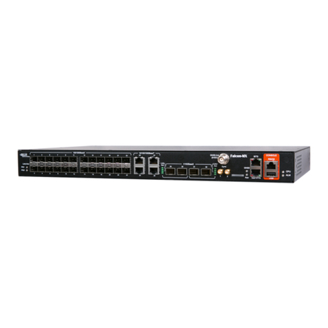
FibroLAN Falcon-RX/812/G/A User manual

Falcon R-Class | User Guide
2
proprietary information
This document contains information, which is proprietary to Fibrolan Ltd.
No part of its contents may be used, copied, disclosed or conveyed to a third party in any manner
whatsoever without prior written permission from Fibrolan Ltd.
Special Notes
The R Class series includes various Falcon-RX models.
Please refer to the Alphabetical Glossary of terms and definitions for clarification of the terminology
found in the User Guide.
The features and characteristics described in this User Guide are common to all R class devices.
For a detailed features vs models cross reference table, please refer to the 'Product Selection Guide'
on Fibrolan website.

Falcon R-Class | User Guide
3
Table of Contents
1.1 R Class series overview ...............................................................................................8
Falcon-RX .......................................................................................................8
1.2 Physical Description ....................................................................................................8
Falcon-RX/812/G.............................................................................................8
1.3 Models List .................................................................................................................9
1.4 Typical Applications.....................................................................................................9
5G Fronthaul & Backhaul Convergence .............................................................9
IIoT Campus deployment .............................................................................. 10
2.1 Block Diagram .......................................................................................................... 11
2.2 R Class series key features ........................................................................................ 12
2.3 Management ............................................................................................................ 12
Management integration................................................................................ 12
OAM & Diagnostics:....................................................................................... 12
2.4 R Class Falcon port features ...................................................................................... 12
3.1 Quick Setup Outline .................................................................................................. 14
3.2 Console Connection and Configuration ....................................................................... 15
Initial IP address settings .............................................................................. 15
3.3 Web GUI .................................................................................................................. 16
4.1 Overview.................................................................................................................. 18
4.2 Frame Processing Overview ....................................................................................... 18
4.3 System Information .................................................................................................. 19
System Information Configuration .................................................................. 19
IP Configuration............................................................................................ 19
IP Interfaces................................................................................................. 21
IP Routes ..................................................................................................... 23
NTP Configuration ......................................................................................... 23
Time Zone .................................................................................................... 26
System Log Configuration .............................................................................. 28
Events .......................................................................................................... 29
4.4 Ports Configuration and Monitoring ............................................................................ 30
Port State ..................................................................................................... 32
SFP Information ............................................................................................ 33
SFP Operational Range .................................................................................. 33
SFP Monitoring.............................................................................................. 34
Traffic Overview............................................................................................ 35
QoS Statistics................................................................................................ 36
QoS Control List Status.................................................................................. 36
Detailed Port Statistics................................................................................... 37
Green Ethernet ............................................................................................. 39
Thermal Protection........................................................................................ 40
4.5 MAC Learning Table .................................................................................................. 41
Configuring the MAC Address Table................................................................ 41
Monitoring the MAC Address Table ................................................................. 43
Navigating the MAC Table.............................................................................. 43
4.6 VLANs and Provider Bridges....................................................................................... 45
VLAN Configuration ....................................................................................... 45
VLAN Membership Status for Combined users ................................................. 52
VLAN Translation .......................................................................................... 53
Provider Bridges (QinQ)................................................................................. 56

Falcon R-Class | User Guide
4
Private VLANs (PVLANs) ................................................................................ 56
VCL .............................................................................................................. 58
Voice VLAN ................................................................................................... 63
Multicast VLAN Registration (MVR) ................................................................. 66
4.7 Quality of Service (QoS) ............................................................................................ 73
QoS Ingress Port Classification....................................................................... 73
QoS Ingress Port Policers .............................................................................. 75
QoS Ingress Queue Policers ........................................................................... 76
QoS Egress Port Schedulers ........................................................................... 77
QoS Egress Port Shapers ............................................................................... 79
QoS Egress Port Tag Remarking..................................................................... 81
Qos Port DSCP Configuration ......................................................................... 82
DSCP Based QoS Ingress Classification ........................................................... 84
DSCP Translation .......................................................................................... 85
QoS Control List Configuration ....................................................................... 87
QCE Configuration......................................................................................... 89
Rate Limiters ................................................................................................ 91
Global Storm Policer Configuration .................................................................92
4.8 Security Features ...................................................................................................... 95
Switch .......................................................................................................... 95
Network Security......................................................................................... 103
Address Resolution Protocol......................................................................... 136
Authentication Server Configuration (AAA).................................................... 141
4.9 SyncCenter Configuration ........................................................................................ 150
Overview .................................................................................................... 150
Mode Configuration ..................................................................................... 150
Sync Source Configuration ........................................................................... 150
SyncCenter Visual Indicators........................................................................ 152
Sync Output................................................................................................ 152
Source Select Configuration ......................................................................... 152
Holdover Configuration................................................................................ 153
Time Attributes Configuration ...................................................................... 154
Time Settings Configuration......................................................................... 154
SyncCenter General/Frequency/Phase/ToD Status......................................... 155
4.10 SyncCenter Monitoring ............................................................................................ 156
Sync Sources and Visual Indicators .............................................................. 156
SyncCenter Source Status............................................................................ 156
Time .......................................................................................................... 157
Sync Output................................................................................................ 157
4.11 GNSS Receiver........................................................................................................ 158
GNSS Antenna Cable Configuration .............................................................. 158
GNSS Status and Alarms.............................................................................. 158
Satellite Status............................................................................................ 160
GNSS Antenna Cable Status ......................................................................... 161
GNSS Receiver Info ..................................................................................... 161
Sky View .................................................................................................... 162
Satellite Count ............................................................................................ 162
4.12 IEEE1588 Precision Time Protocol ............................................................................ 164
PTP Clock Configuration .............................................................................. 165
PTP Clock’s Configuration and Status............................................................ 167
PTP Monitoring ........................................................................................... 171

Falcon R-Class | User Guide
5
PTP Slave Table .......................................................................................... 174
4.13 Synchronous Ethernet (SyncE)................................................................................. 176
Overview .................................................................................................... 176
SyncE Port Configuration ............................................................................. 177
SyncE Port Monitoring ................................................................................. 179
4.14 External Sync Ports Configuration ............................................................................ 181
External Status ........................................................................................... 181
4.15 Spanning Tree ........................................................................................................ 183
Understanding RSTP and MSTP.................................................................... 183
Bridge settings............................................................................................ 186
MSTI Configuration ..................................................................................... 187
MSTI Priority Configuration .......................................................................... 189
CIST Port Configuration ............................................................................... 189
MSTI Port Configuration .............................................................................. 191
Spanning Tree Monitoring............................................................................ 192
4.16 IP Multicast ............................................................................................................ 196
IGMP Snooping Configuration ...................................................................... 196
IGMP Snooping VLAN Configuration ............................................................. 198
IGMP Snooping Port Group Filtering Configuration......................................... 200
IGMP Snooping Status ................................................................................. 201
IGMP Snooping Groups Information ............................................................. 202
IGMP SFM Information ................................................................................ 203
MLD Snooping Configuration........................................................................ 204
MLD Snooping VLAN Configuration ............................................................... 205
MLD Snooping Status .................................................................................. 207
MLD Snooping Groups Information............................................................... 209
MLD SFM Information.................................................................................. 209
4.17 Link Aggregation..................................................................................................... 210
Common Aggregation Configuration ............................................................. 211
Aggregation Group and Mode Configuration.................................................. 212
LACP Configuration ..................................................................................... 213
Aggregation Status...................................................................................... 214
LACP Monitoring.......................................................................................... 214
4.18 LLDP-Link Discovery................................................................................................ 218
LLDP Configuration ..................................................................................... 218
LLDP Media Configuration............................................................................ 220
LLDP Monitoring.......................................................................................... 227
4.19 Link OAM................................................................................................................ 234
Link OAM Port Configuration ........................................................................ 235
Link Event Configuration for selected Port..................................................... 237
Detailed Link OAM Statistics for selected port ............................................... 238
Detailed Link OAM Status for selected port ................................................... 239
Detailed Link OAM Link Events Status for selected port.................................. 240
4.20 RMON (Remote Network Monitoring) ....................................................................... 244
RMON Statistics Configuration...................................................................... 244
RMON History Configuration ........................................................................ 244
RMON Alarm Configuration .......................................................................... 245
RMON Event Configuration .......................................................................... 246
4.21 Loop Protection....................................................................................................... 247
Loop Protection Status ................................................................................ 248
4.22 GVRP Configuration................................................................................................. 250

Falcon R-Class | User Guide
6
4.23 sFlow Consideration ................................................................................................ 251
sFlow Configuration displays ........................................................................ 251
sFlow Statistics ........................................................................................... 253
4.24 UDLD Configuration ................................................................................................ 255
UDLD Port Configuration.............................................................................. 255
Detailed UDLD Status for Port 1 ................................................................... 256
5.1 General Introduction ............................................................................................... 257
System Information..................................................................................... 257
System Status............................................................................................. 258
CPU Load.................................................................................................... 259
IP Status .................................................................................................... 259
System Log Information .............................................................................. 260
Detailed System Log Information ................................................................. 262
5.2 DHCP (Dynamic Host Configuration Protocol)............................................................ 263
DHCP Server Mode Configuration ................................................................. 263
DHCP Server Excluded IP Configuration ........................................................ 264
DHCP Server Pool Configuration ................................................................... 265
DHCP Snooping Configuration ...................................................................... 266
Dynamic DHCP Snooping ............................................................................. 267
DHCP Relay Configuration............................................................................ 268
DHCP Relay Statistics .................................................................................. 269
DHCP Server Statistics ................................................................................. 270
DHCP Server Binding IP............................................................................... 271
DHCP Server Declined IP ............................................................................. 272
DHCP Detailed Statistics Port 1 .................................................................... 272
5.3 Simple Network Management Protocol (SNMP) ......................................................... 275
SNMP System Configuration......................................................................... 275
Trap Configuration ...................................................................................... 276
Trap Source Configurations.......................................................................... 278
SNMPv3 Community Configuration ............................................................... 278
SNMPv3 User Configuration ......................................................................... 279
SNMPv3 Group Configuration ....................................................................... 280
SNMPv3 View Configuration ......................................................................... 281
SNMPv3 Access Configuration ...................................................................... 282
5.4 Supported SNMP MIBs............................................................................................. 284
5.5 Command Line Interface (CLI)................................................................................. 285
SSH Configuration ....................................................................................... 285
HTTP Secure (HTTPS) ................................................................................. 285
5.6 Events Configuration ............................................................................................... 285
Events Configuration table ........................................................................... 286
5.7 Web Interface......................................................................................................... 287
Port Configuration ....................................................................................... 287
User Configuration & Edit User..................................................................... 287
Authentication Method Configuration............................................................ 289
Authentication Servers Configuration............................................................ 289
Access Management Configuration ............................................................... 289
5.8 RMON Overview...................................................................................................... 290
RMON Statistics Status Overview.................................................................. 290
RMON History Overview .............................................................................. 291
RMON Alarm Overview ................................................................................ 293
RMON Event Overview ................................................................................ 294

Falcon R-Class | User Guide
7
Ping IPv4.................................................................................................... 295
Ping IPv6.................................................................................................... 297
Link OAM MIB Retrieval ............................................................................... 298
VeriPHY Cable Diagnostics ........................................................................... 299
7.1 Restart Device ........................................................................................................ 301
7.2 Factory Defaults...................................................................................................... 301
7.3 Software Management ............................................................................................ 302
Software Image Select ................................................................................ 302
7.4 Configuration Management...................................................................................... 304
Save startup configuration ........................................................................... 304
Download Configuration .............................................................................. 304
Upload Configuration................................................................................... 304
Activate ...................................................................................................... 305
Delete ........................................................................................................ 305
7.5 Power Supply Overview ........................................................................................... 306
AC Power Supply......................................................................................... 306
DC Power Supplies ...................................................................................... 307
7.6 Laser Safety ........................................................................................................... 308
8.1 Warranty Limitation................................................................................................. 309
9.1 General Glossary of Terms....................................................................................... 310
9.2
General Glossary of Terms
....................................................................................... 310
9.3 Alphabetical Glossary of Terms ................................................................................ 317

Falcon R-Class | User Guide
8
1Introduction
1.1 R Class series overview
Falcon-RX
Falcon-RX is a high performance, 5G xHaul Timing Aware O-RAN Switch & PTP Grandmaster. It is a
high capacity, low latency transport and high precision synchronization device that enables 5G RAN
operation at its optimal throughput, on both telecom and enterprise environments.
The Falcon-RX combines the best of breed of the Transport and Timing worlds, in a single powerful
package. Both elements are critical for 5G fronthaul deployments, along with support for the latest
O-RAN architectures and recommendations.
The Falcon-RX is equipped with up to twenty (20) multi-rate 10G SFP+ ports or eight (8) 25G SFP28
ports, based on user configuration. Additionally, one tri-speed Copper management port is included.
All ports can operate at full wire speed, with a total forwarding capacity of 200Gbps.
The system offers advanced Quality of Service (QoS) features including classification and mapping
based on layer 1 through layer 4 attributes, rate limiting, highly flexible scheduling, queuing and
shaping options and MEF defined services.
1.2 Physical Description
Falcon-RX/812/G
Figure 1-1: Falcon-RX/812/G front panel
Figure 1-2: Falcon-RX/812/G back panel
Table 1-1: Falcon-RX/812/G Front Panel Description
①
12x 1/10G BaseX
⑧
LEDs indicators Link/Activity (per port)
②
8x 1/10/25G BaseX
⑨
2x Sync SMA input/output –1PPS/10 MHz
③
1x 10/100/1000 BaseT (management)
⑩
RJ45 input/output ToD/1PPS
④
RJ45 and USB Console
⑪
LEDs indicators Sync/GNSS/CPU/Aux.
⑤
GNSS antenna TNC connector (5VDC)
⑫
Expansion module for Rubidium clock
⑥
1.5 / 2 Mbps BITS input/output
⑬
PSU1 –AC/DC options supported
⑦
LEDs indicators PSU1/PSU2
⑭
PSU2 –AC/DC options supported

Falcon R-Class | User Guide
9
1.3 Models List
Table 1-2:Falcon-RX models list
Model
Part
#
Description
Falcon-RX/812/G/A
7160
Timing Aware xHaul Switch, 12x10G (SFP+), 8x25G (SFP28) ports, Advanced
Timing spec w/ GNSS Rx, 1 removable AC power supply (FPS10012/A)
Falcon-RX/812/G/D
7161
Timing Aware xHaul Switch, 12x10G (SFP+), 8x25G (SFP28) ports, Advanced
Timing spec w/ GNSS Rx, 1 removable DC power supply (FPS10012/D)
1.4 Typical Applications
5G Fronthaul & Backhaul Convergence
Evolved mobile networks requires high level of synchronization to operate. The required accuracy
level increases as the networks further evolve, reaching the point the expected time error of
nanoseconds is needed in the 5G Fronthaul. The Falcon-RX ability to provide this level of
synchronization, on top of its line rate Ethernet forwarding, makes it the ideal Fronthaul switch.
Additionally, the Falcon-RX can also provide backhaul connection to complete gNodeB units towards
the 5G Core.
Figure 1-3: Falcon-RX typical xHaul application

Falcon R-Class | User Guide
10
IIoT Campus deployment
Modern industrial campuses and factories are being designed to accommodate high level of
automation and mobility in production, which dictates specific requirement for synchronization. In
such environment where, man and machine coexist and work together side by side all actions must
be coordinated and mutually aware. Synchronized packet networks and time sensitive networking
(TSN) are a key element in building these enrolments.
Figure 1-4: Falcon-RX in IIoT campus deployment.

Falcon R-Class | User Guide
11
2System Description
2.1 Block Diagram
Figure 2-1: R Class functional block diagram

Falcon R-Class | User Guide
12
2.2 R Class series key features
•LTE/5G xHaul Transport and Timing RAN switch
•Integrated PTP Grandmaster
•Compatible with O-RAN architectures
•High capacity, low latency
•Extensive Sync and Timing with SyncE and PTP (PTRC/GM, BC, TC)
•Sub nanosecond timestamping, Class C/D performance
•Time Sensitive Networking support
•Based on 4th generation Falcon architecture
•Advanced QoS and service level traffic management
•Advanced OAM and management capabilities
•Multiple protection mechanisms for link, path, and ring service resilience
2.3 Management
The R Class Falcon can be remotely managed via a variety of mechanisms/ platforms at virtually no
integration efforts:
IP Based (in-band): SNMP (v1/v2/v3), Telnet, SSH, Web (HTTP, HTTPS).
Console (RJ-45): RS-232 (115,200Bd), CLI (Cisco like).
OAM/IEEE802.3ah: when connected to third party edge switch that supports the standard.
Management integration
Integration with 3rd party network management systems can be achieved via SNMP protocol, in
addition to the following standards: NTPV4, SYSLOG, RADIUS, TACACS, DHCP, LACP, LLDP.
OAM & Diagnostics:
•IEEE802.3ah link OAM
•IEEE802.1ag CFM
•ITU-T Y.1731 PM (HW based measurements)
•Copper TDR
•SFP diagnostics (SFF-8472)
•Traffic mirroring
2.4 R Class Falcon port features
R Class ports can be configured to support special data-plain functions. extended traffic handling
capabilities, more functionality and processing power. These capabilities are Software and Firmware
based and therefore field upgradeable and configurable.
The following special features are supported by the R Class series models ports:
•Synchronous Ethernet
•IEEE1588-2008 - PTP.
•MEF 20: specifies MEF User to Network Interface (UNI) Type 2.

Falcon R-Class | User Guide
13
•MEF 22.1: Mobile Backhaul Phase 2
•Per port / queue policing
•Per port / queue shaping
•Per Port Counters: The R Class models support frame and byte counters per port.
•Link OAM (IEEE802.3ah) and Service OAM (based on IEEE 802.1ag, ITU-T Y.1731)
•ITU Y.1731 data-plane support–several functions of this standard require HW based support.
These functions are:
oLoss measurement
oDelay measurement
oDelay variation measurement
•Linear Ethernet Protection Switching (G.8031)
•Ethernet Ring Protection Switching (G.8032v2)
•Power Link ports support the implementation of the following:
Note: The above feature list represents the current status. It is expected that further features will
be added in future System Software releases

Falcon R-Class | User Guide
14
3Getting Started
3.1 Quick Setup Outline
To set up the R Class models carry out the following steps:
1Mount the device at its location (rack or desktop).
2Install the SFP transceivers.
3Connect the unit to a console and a power source (Figure 3-1).
4Verify that the Power (PS1, PS2 or both) LEDs are green lit.
5Connect required cables to ports: twisted pair (RJ45 Ethernet) and fiber (Ethernet SFPs).
6Verify that the ports Link and Speed LEDs are lit per connected interfaces.
7Configure the selected device via the console to assign management IP address or use default IP
address (192.168.1.90)
8Establish management access via SSH, Telnet or Web GUI (4.1.2).
9For a general configuration procedure please refer to the Getting Started Quick Guide located at
www.Fibrolan.com (Resources > Documents > Quick Guides).
Note: Remote management requires basic IP configuration.

Falcon R-Class | User Guide
15
3.2 Console Connection and Configuration
Note: Applicable to R Class series devices.
Figure 3-1: Falcon console connection
To enable basic console connection for initial setup, carry out the following steps:
1. Use an RJ-45-to-DB-9 console cable and insert the RJ-45 connector into the console port on
the front panel. Alternately connect USB-to-USB from PC directly to USB port on Falcon front
panel. Configure the baud rate and character format of the PC or terminal to match these
console port default characteristics:
115200 baud, 8 data bits, 1 stop bit, No parity, None (flow control).
2. Connect the device to a power source and wait until it boots up.
3. The system prompts you to log in.
Default username: moose Default password: 1234.
Note: if you experiment difficulty in the connection, contact Fibrolan support
Initial IP address settings
This first configuration is done via the console; it enables the switch to connect to the IP network.
Once the unit IP address is set via console, the system can be accessed through Web, Telnet, SSH or
any other management options.
Initial IP setup can be implemented by manually setting the IP address Parameters or by an automatic
DHCP setup (if a DHCP server is present).
To assign a new IP address to the device enter the following CLI commands:
➢configure terminal
➢interface vlan 1
➢ip address 192.168.1.90 255.255.255.0
The Falcon R class will initially boot-up with this default IP address: 192.168.1.90/24.

Falcon R-Class | User Guide
16
3.3 Web GUI
The Web management is accessed by setting the required IP address in the URL Browser. When
accessing the devices via the Web interface, its initial Port State Overview window is displayed. as
shown below.
Web GUI: Monitor > Ports > State
①
IP address of device in explorer URL line.
②
Four functionality management menus: Configuration, Monitor, Diagnostics and
Maintenance
Configuration: For setting all system parameters relevant to proper operation of the
device.
Monitor: Displays a variety of statuses from the device and other device info that enable
system administrator to following up and check if the device is working properly.
Diagnostics: Includes tools to diagnose and troubleshoot networking issues
Maintenance: For restarting your device, returning to factory defaults and upgrading
your device.
③
Main bar: consists of the following buttons:
Show help: online help specific to the displayed dynamic configuration screen.
Logout: User can end access to device web site.
Home: Access to device front panel.
SyncCenter: Control center of system synchronization interfaces and timing signal
and their distribution.
PTP: Manage PTP clock instances
Save running config: After

Falcon R-Class | User Guide
17
④
Dynamic configuration section: Displays detailed data for the selected from one of the
functionality menus.
•Auto-refresh: Check this box to refresh the page automatically. Automatic
refresh occurs every 3 seconds
•Refresh: Click to refresh the page.

Falcon R-Class | User Guide
18
4Functional Description
4.1 Overview
This section provides introduction to the R Class series functionality and instructions for
configuration and monitoring.
The configuration and monitoring functionalities can be accessed via various management
interfaces. Sections 4 demonstrates the configuration various functions and setting mainly using the
Web interface. However, any configuration can be implemented using other management interfaces
(CLI, Telnet, and SNMP).
4.2 Frame Processing Overview
This section provides a general description of the Frame Forwarding Process at the R Class series
from the input port toward the output port, as illustrated below.
Figure 4-1: Frame Forwarding Diagram
Input frame flow
Frames received on the input port (MAC layer) are handed to the classifiers in order to classify frames
into different flows (e.g., management frames, specific service/user frames, etc.). Following the
classification, the frames are passed to the Policer. If the Policer is not selected the frames pass
untouched. From the Policer the frames enter the Ingress Queue. Some prioritization algorithms are
used to handle traffic and to avoid buffer overrun and Frame loss.
Output frame flow
The frames, which pass from the Ingress Queue, are transferred to the Egress Queue (8 parallel
queues). The topmost queue handles management frames injected by the CPU, which have super
priority over the other four queues. The remaining queues transfer data frames. At this stage, a
scheduling process is taking place in order to decide which frame will be sent out of the port (out of
the 8 candidate queues). For scheduling either a Strict-Priority or a Weighted Fair Queuing algorithm
is being used. The output of the queue is passed to the Shaper. If the Shaper is not selected the frame
passes untouched. The frames are then passed to the Rewriter. The Rewriter examines the frame
header information and adjusts it if required. From there on the frame is sent to the output port
(MAC layer).
Packet forwarding
Packet forwarding decisions are based on the following criteria:

Falcon R-Class | User Guide
19
•ACL:(Access Control List) The ACL can drop a frame or redirect it to a specific port
•MAC address and VLAN: The standard Ethernet switch forwarding –a frame is forwarded by
searching the learn-table and sending it to the port where the MAC-address + VLAN was learnt.
If the address is not found, or the frame is a broadcast frame it will be sent to all the other
member ports of the VLAN.
4.3 System Information
The switch system information is provided here.
The display is similar in all falcon series
System Information Configuration
Web GUI: Configuration > System > Information
Figure 4-2: System Information Configuration
Table 4-1: System Information Configuration Parameters
System Contact
The textual identification of the contact person for this managed
node, together with information on how to contact this person. The
allowed string length is 0 to 255, and the allowed content is the
ASCII characters from 32 to 126.
System Name
An administratively assigned name for this managed node. By
convention, this is the node's fully qualified domain name. A domain
name is a text string drawn from the alphabet (A-Za-z), digits (0-9),
minus sign (-). No space characters are permitted as part of a name.
The first character must be an alpha character. And the first or last
character must not be a minus sign. The allowed string length is 0 to
255.
System Location
The physical location of this node (e.g., telephone closet, 3rd floor).
The allowed string length is 0 to 255, and the allowed content is the
ASCII characters from 32 to 126.
IP Configuration
Configure IP basic settings, control IP interfaces and IP routes. The maximum number of interfaces
supported is 32 and the maximum number of routes is 32.

Falcon R-Class | User Guide
20
Web GUI: Configuration > System > IP
Figure 4-3: IP Configuration
Table 4-2: IP Configuration Parameters
IP Configuration- Basic Settings
Mode
Configure whether the IP stack should act as a Host or a Router. In Host
mode, IP traffic between interfaces will not be routed. In Router mode
traffic is routed between all interfaces.
DNS Server
Controls the DNS name resolution done by the switch. There are four
servers available for configuration, and the index of the server presents
the preference (less index has higher priority) in doing DNS name
resolution. System selects the active DNS server from configuration in
turn, if the preferred server does not respond in five attempts.
The following modes are supported:
•No DNS server: No DNS server will be used.
•Configured IPv4: Explicitly provide the valid IPv4 unicast address of
the DNS Server in dotted decimal notation. Make sure the configured
DNS server could be reachable (e.g., via PING) for activating DNS
service
•Configured IPv6: Explicitly provide the valid IPv6 unicast (except link
local) address of the DNS Server. Make sure the configured DNS
server could be reachable (e.g., via PING6) for activating DNS service.
•From any DHCPv4 interfaces: The first DNS server offered from a
DHCPv4 lease to a DHCPv4-enabled interface will be used.
•From this DHCPv4 interface: Specify from which DHCPv4-enabled
interface a provided DNS server should be preferred.
•From any DHCPv6 interfaces: The first DNS server offered from a
DHCPv6 lease to a DHCPv6-enabled interface will be used.
•From this DHCPv6 interface: Specify from which DHCPv6-enabled
interface a provided DNS server should be preferred.
DNS Proxy
When DNS proxy is enabled, system will relay DNS requests to the
currently configured DNS server, and reply as a DNS resolver to the client
devices on the network.
Only IPv4 DNS proxy is currently supported.
This manual suits for next models
1
Table of contents
Other FibroLAN Network Hardware manuals
Popular Network Hardware manuals by other brands
ZyXEL Communications
ZyXEL Communications FMG3010-R20A user guide
Silicon Laboratories
Silicon Laboratories ETRX358USB manual

HP
HP 85027A Operating and service manual
Paradyne
Paradyne COMSPHERE 3550 Series installation instructions
ICP CON
ICP CON PPDS-700-MTCP Series quick start

Ubiquiti
Ubiquiti UBB quick start guide

