Fike FlamQuench II DN200 User manual

8.8520.00.0
FlamQuench IIM
VENTING WITH FLAME AND PARTICLE RETENTION
INSTALLATION AND OPERATING INSTRUCTIONS
EXPLOSION PROTECTION SYSTEMS

Manual P/N: 8.8520.00.0 Table of Contents – Page: 1
Revision : A – October 15, 2001
TABLE OF CONTENTS
PAGE #
1. INTRODUCTION......................................................................................................................... 1
2. GENERAL INFORMATION......................................................................................................... 1
2.1 DESCRIPTION................................................................................................................... 1
2.2 SERVICE QUALIFICATIONS............................................................................................. 1
2.3 PERSONNEL SAFETY...................................................................................................... 1
2.4 FLAMQUENCH IISAFETY ................................................................................................. 1
2.5 FLAMQUENCH IIINSTALLATION PROCEDURE.............................................................. 1
2.6 FLAMQUENCH IIREMOVAL PROCEDURE...................................................................... 2
2.7 IDENTIFICATION OF FLAMQUENCH II............................................................................. 2
3. INSTALLATION.......................................................................................................................... 2
4. SUPPORT CONSIDERATIONS.................................................................................................. 2
5. REFURBISHMENT INSTRUCTIONS.......................................................................................... 3
5.1 FILTER HANDLING WARNING.......................................................................................... 3
5.2 FILTER REPLACEMENT................................................................................................... 3
5.2.1 REMOVE FILTER (REFER TO FIGURES 4 AND 5, PAGES 11 AND 12)........................ 3
5.2.2 INSTALLATION OF FILTER(S) (REFER TO FIGURE 6, PAGE 13) ............................. 3
5.3 REFURBISH KITS ............................................................................................................. 4
5.4 TOOLS NEEDED FOR REFURBISHMENT (NOT INCLUDED AS PART OF KIT) ............4
6. SCHEDULED MAINTENANCE ................................................................................................... 5
6.1 EVERY THREE (3) MONTHS ............................................................................................ 5
7. MAINTENANCE AFTER EACH FLAMQUENCH IIACTIVATION ............................................. 5
8. EXPLOSION VENT REQUIREMENTS ....................................................................................... 5

Manual P/N: 8.8520.00.0 Tables and Figures –Page: 1
Revision : A –October 15, 2001
TABLES AND FIGURES
PAGE #
Table 1 Refurbish Kits................................................................................................................... 4
Table 2 FlamQuench IIEnglish Specifications........................................................................... 6
Table 3 FlamQuench IIMetric Specifications............................................................................. 7
Figure 1 Installation Diagram......................................................................................................... 8
Figure 2 Installation Orientation..................................................................................................... 9
Figure 3 FlamQuench IISpecifications..................................................................................... 10
Figure 4 FlamQuench IIAssembly ............................................................................................ 11
Figure 5 FlamQuench IIAssembly ............................................................................................ 12
Figure 6 Filter Installation.............................................................................................................13

Manual P/N: 8.8520.00.0 Page: 1
Revision : A –October 15, 2001
1. INTRODUCTION
This document is intended to provide information to assist with the installation, use, maintenance and
replacement of the Fike FlamQuench IIM.
Fike Corporation has designed and manufactures the FlamQuench IIin two versions: an imperial size unit
specified according to NA standards, available in size 8”through 40”; and a metric version specified and built
for the CE market, available in size DN200 through DN1000.
2. GENERAL INFORMATION
2.1 DESCRIPTION
The Fike FlamQuench IIMis designed to allow for indoor explosion venting with flame arresting and
particulate retention. It consists of various layers of high temperature stainless steel that retain burned and
unburned dust and absorb heat produced during the explosion.
2.2 SERVICE QUALIFICATIONS
The information contained in this document is provided for reference purposes only. For further product
information or ordering replacement parts, please contact your local Fike Branch Office or Representative
(details of which can be found on the back page) or:
2.3 PERSONNEL SAFETY
WARNING: Mark a security distance of 8 feet (3 meters) around FlamQuench IIMStay out of this
area.
2.4 FlamQuench IISAFETY
WARNING: Any damage to the Filter may cause the FlamQuench IIMto malfunction, which may
result in a dust explosion in the surrounding area.
2.5 FlamQuench IIINSTALLATION PROCEDURE
WARNING: When installing do not damage filter. Any damage to filter may compromise the function
of the FlamQuench IIM.
Refer to Figure 1 (page 8) for assembly diagram.
Step 1: All system components shall be installed and the electrical and control systems thoroughly checked
by a qualified technician before proceeding with installation.
Step 2: Use provided lift ring(s) when installing FlamQuench IIM. The rings are located on the top and
bottom weldments. Do not attempt to lift FlamQuench IIMby any other method.
Step 3: Carefully clean gasket, explosion vent, and bolting pad surface (frame or flangering).
Step 4: Place gasket onto bolting pad
(AFM30/34 or similar is the recommended gasket material. Sealant
may be used, type may vary depending on process requirements)
. Be sure to line up holes.
Step 5: Place the explosion vent onto gasket with ID tag lettering facing up. Align holes.
Note: Explosion vent may be placed onto the FlamQuench IIMfirst. However you must wait until the
sealant has dried before continuing the installation. Follow the instructions on sealant for drying time.
WARNING: TAKE EXTREME CAUTION NOT TO DAMAGE EXPLOSION VENT WHEN INSTALLING
FlamQuench II. DAMAGE TO THE EXPLOSION VENT WILL CAUSE IT TO MALFUNCTION.

Page: 2 Manual P/N: 8.8520.00.0
Revision : A –October 15, 2001
Step 6: Carefully place FlamQuench IIMon top of explosion vent making sure holes are lined up before
placing all the weight on the explosion vent.
Step 7: Fasten the FlamQuench IIMto the bolting pad using either 18-8 or 304 stainless steel hardware.
Torque to 35-40 foot pounds (48-54 N-m).
Step 8: Connect Burst Indicator. (See Installation Instructions on connecting BI)
Note: Cables attached to lifting rings can be used to help support the FlamQuench IIM. Do not attempt to
support the FlamQuench IIMusing any other method other than the lift rings.
2.6 FlamQuench IIREMOVAL PROCEDURE
Caution: Before removing FlamQuench IIM, carefully check the surface temperature. Make sure it is
not too hot to handle.
Do not disassemble the FlamQuench IIMwhen mounted to a vessel.
Step 1: Shut down process if not already shut down.
Step 2: Remove hardware holding FlamQuench IIMto vessel.
Step 3: Use only the provided lift rings for lifting.
Step 4: Follow instructions in Section 5 (page 3) for refurbishment.
2.7 IDENTIFICATION OF FlamQuench II
For the purpose of identifying the FlamQuench IIMand ordering replacement parts and refurbishment kits the
FlamQuench IIMhas been permanently tagged. The FlamQuench IIMhas separate ID tags for each
component. See Figures 4 & 5 (pages 11 & 12) for ID tag locations. The ID tags contain the following
information: Size, Part Number and Lot Number. The explosion vent will be marked separately.
3.
INSTALLATION
•Keep a minimum distance of 2 feet (0.7 meters) between the FlamQuench IIMand any equipment or
walls to allow for proper venting.
•FlamQuench IIMmay be installed anywhere between vertical and horizontal. See Figure 2 (page 9).
Fike Corporation shall evaluate any deviation from this orientation.
•The FlamQuench IIMrequires sufficient support based on the FlamQuench IIMweight and reaction
force created during activation. Refer to Table 2 (page 6) or Table 3 (Page 7) and Figure 3 (page 10) for
FlamQuench IIMphysical specifications.
4. SUPPORT CONSIDERATIONS
The FlamQuench IIMshould be supported to prevent damage to the vessel it is protecting. If the vessel is
sufficiently sturdy, the flange connection may be used to support the FlamQuench IIM. Weight and angle
must be considered when evaluating vessel strength for mounting. If the vessel wall is not sufficient to
support the FlamQuench IIM, additional reinforcement should be provided.
Where lighter weight vessels are used, the FlamQuench IIMshould be supported independently. This may
be accomplished by attaching cables to the lifting rings on the top and side of the FlamQuench IIMRefer to
Figure 2 (page 9).

Manual P/N: 8.8520.00.0 Page: 3
Revision : A –October 15, 2001
5. REFURBISHMENT INSTRUCTIONS
5.1 FILTER HANDLING WARNING
WARNING: To prevent possible injury (cuts & scrapes), wear leather gloves when handling the filters.
5.2 FILTER REPLACEMENT
5.2.1 REMOVE FILTER (Refer to Figures 4 and 5, pages 11 and 12)
Step 1: Follow removal procedures in Section 2.6.
Step 2: Remove nuts, bolts and washers and discard.
Step 3: Use supplied lift rings to remove Top Frame Weldment. Be sure to remove lower bands on larger
FlamQuench II.
Step 4: Remove Top and Side Filters and dispose of properly.
Step 5: Remove Fiber Frax rings and discard in a safe manner.
5.2.2 INSTALLATION OF FILTER(S) (Refer to Figure 6, page 13)
CAUTION: BEFORE INSTALLING NEW FILTER, THOUROUGLY INSPECT FRAME FOR STRESS
FRACTURES. IF FRACTURES ARE FOUND, REPLACE ENTIRE FRAME.
Step 1: Place Fiber Frax ring into Bottom Weldment. Be carefull not to tear ring.
Step 2: Carefully install Side Filter into Bottom Weldment, ID tag down. If Filter is damaged in any way, it
may compromise the function of the filter. For easier installation turn assembly upside down to
install filter. See Figure 6A (page 13). Be sure to note location of ID tag (Refer to Figure 4 or 5).
Step 3: Place Fiber Frax ring on top of Side Filter. See Figure 6B (page 13).
Step 4: FlamQuench II sizes 8”–20”(DN200 –DN500) skip to Step 9.
Step 5: FlamQuench II sizes 24”–40”(DN600 –DN1000) install Center Ring Support Weldment. (Refer to
Figure 5, page 12)
Step 6: Place Fiber Frax ring on top of Center Ring Support Weldment.
Step 7: Carefully install Side Filter into Center Ring Support Weldment
Step 8: Place Fiber Frax ring on top of Side Filter.
Step 9: Lay the Inner Top Filter on top of the Fiber Frax (ID tag up). Be sure to center this part on top of the
Filter. See Figure 6B (page 13). Be sure to note location of ID tag.
Step 10: Lay the Outer Top Filter on top of the Inner Top Filter (ID tag up). Be sure to center. See Figure 6B
(page 13). Be sure to note location of ID tag.
Step 11: Carefully lower Top Frame Weldment onto filter assembly. Align holes in top weldment with holes
in bottom weldment. In order to line-up holes the assembly needs to be compressed using 3 bar
clamps. Place the bar clamps equaly spaced around the diameter. Slowly tighten each bar clamp
until the holes line-up. See Figure 6C (page 13).
Step 12: Install new hardware provided. DO NOT USE OLD HARDWARE! Torque all hardware to 35 ft-lbs
(48 N-m).
Step 13: Refurbishment complete. Refer to Section 2.5 (page 1) for installation.

Page: 4 Manual P/N: 8.8520.00.0
Revision : A –October 15, 2001
5.3 REFURBISH KITS
Each Refurbish Kit contains the following components:
•Hardware (nuts, bolts, washers)
•Top Inner Filter
•Top Outer Filter
•Side Filter (s)
•Fiber Frax Rings
•FlamQuench IIMInstallation and Operation Manual (E06-045)
FlamQuench IIMSize Kit Part Number – English Kit Part Number – Metric
8” (DN200) E85-039-08 910020
12” (DN300) E85-039-12 910021
14” (DN350) E85-039-14 910022
16” (DN400) E85-039-16 910023
20” (DN500) E85-039-20 910024
24” (DN600) E85-039-24 910025
30” (DN750) E85-039-30 910026
DN800 Not Available 910027 *
36” (DN900) E85-039-36 910027 *
40” (DN1000) E85-039-40 910028
* Note: DN800 and DN900 FlamQuench IIboth use the same filter elements.
Table 1 Refurbish Kits
5.4 TOOLS NEEDED FOR REFURBISHMENT (NOT INCLUDED AS PART OF KIT)
•Torque wrench
•Bar clamps

Manual P/N: 8.8520.00.0 Page: 5
Revision : A –October 15, 2001
6. SCHEDULED MAINTENANCE
All system components should be thoroughly inspected by factory trained personnel. Following are specific
requirements. Additional maintenance may be required depending on process and environmental conditions.
6.1 EVERY THREE (3) MONTHS
•Visually inspect the system.
•Keep filter free of dust. Use soft brush or vacuum to remove dust from filter.
•Check for loose hardware.
•The explosion vent is maintenance free.
7. MAINTENANCE AFTER EACH FlamQuench IIACTIVATION
Replacement is required after every activation. This includes replacing filters and hardware (See Section 5,
page 3).
8. EXPLOSION VENT REQUIREMENTS
The following round Explosion Vents have been approved for use in conjunction with the FlamQuench IIM.
•CV
•CV-S
•CV-CF
•CV-H
Burst Indicators are required on all explosion vents when used with a FlamQuench IIM.

Page: 6 Manual P/N: 8.8520.00.0
Revision : A –October 15, 2001
Table 2 FlamQuench IIEnglish Specifications
(Refer to Figure 3)
FQ II
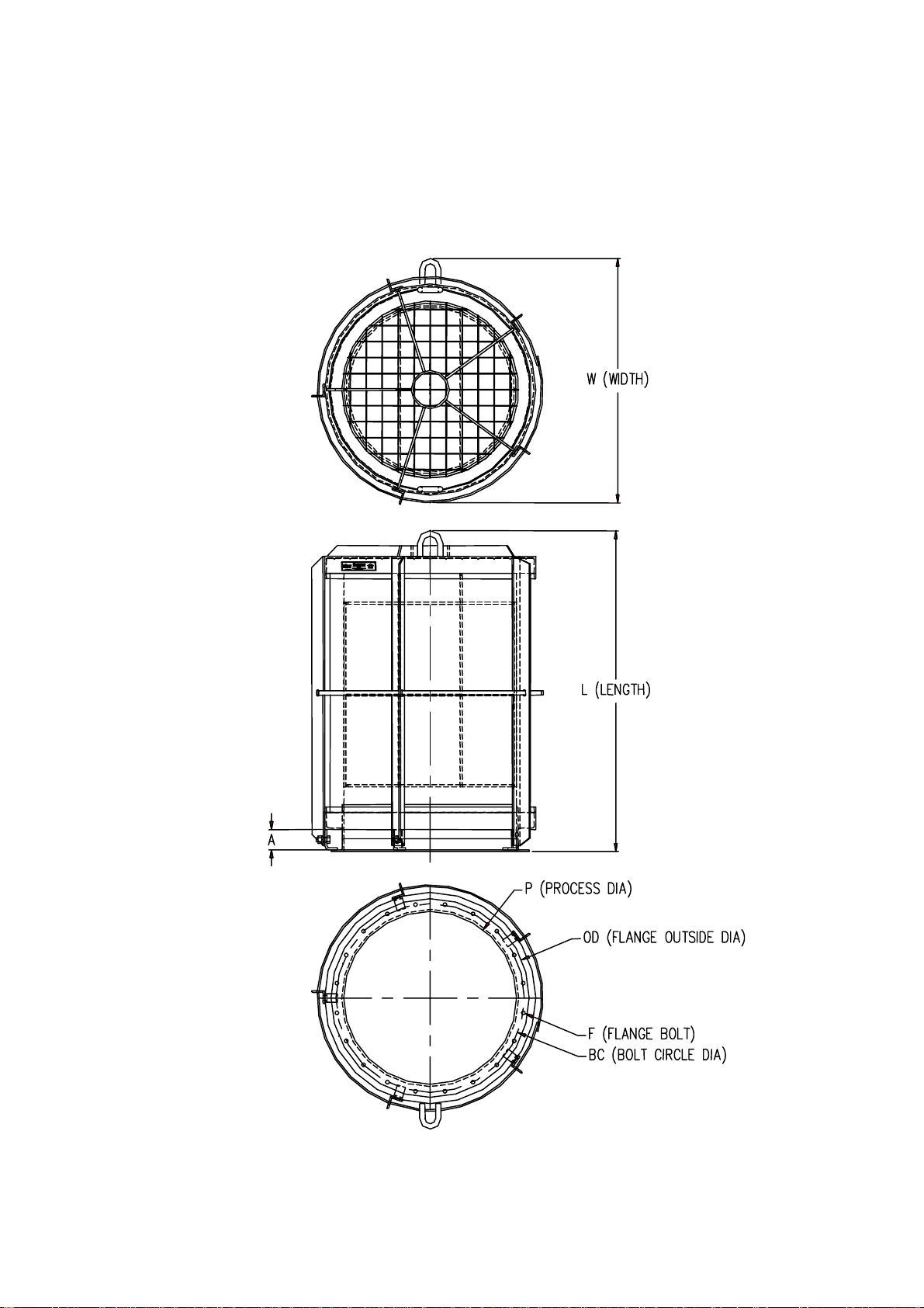
SIZE PODBCF
BOLT
QTY TORQUE
(FT-LBS.)
8”8 1/8 10 5/8 9 ½3/8 8 30
12”12 3/16 15 3/16 13 13/16 7/16 12 30
14”14 3/16 17 3/16 15 13/16 7/16 12 30
16”16 ¼19 ¼18 1/8 7/16 16 30
20”20 ¼23 ¼22 1/8 7/16 20 30
24”24 ¼27 ¼26 1/8 7/16 20 30
30”30 ¼34 ¼32 ½9/16 28 50
36”26 ¼40 ¼38 ½9/16 32 50
40”40 ¼44 ¼42 ½9/16 36 50
NOTE: Flange stud torque values are based on using 1/8" Garlock 3600 gasket material and lightly
oiled and freely running threads.
FQ II
SIZE LWA
WT
LBS. GASKET
INSIDE DIA GASKET
OUTSIDE DIA
8”23 ½13 1 ¾44 8 1/8 10 5/8
12”26 ¼19 1 ¾80 12 3/16 15 3/16
14”31 ½22 ¼2 ½113 14 3/16 17 3/16
16”35 ½25 2 ½168 16 ¼19 ¼
20”37 ½28 ½2 ½199 20 ¼23 ¼
24”57 ¾32 ½2 ½402 24 ¼27 ¼
30”86 ¼38 ¾2 ½635 30 ¼34 ¼
36”88 ¼46 ¼2 ½804 26 ¼40 ¼
40”88 ¼49 ¾2 ½965 40 ¼44 ¼
NOTE: All specifications are subject to change and should be used for reference only.

Manual P/N: 8.8520.00.0 Page: 7
Revision : A –October 15, 2001
Table 3 FlamQuench IIMetric Specifications
(Refer to Figure 3)
FQ II
SIZE PODBCF
BOLT
QTY TORQUE
(N-m)
DN200 208 268 242 10 8 40
Dn300 310 390 355 12 12 33/80**
DN350 342 422 387 12 12 33/80**
DN400 393 483 443 12 16 33/80**
DN500 494 584 544 12 20 33/80**
DN600 596 686 646 12 20 33/80**
DN750 743 843 798 12 28 33/80**
DN800 799 899 854 12 28 33/80**
DN900 900 1000 935 12 32 33/80**
DN1000 1002 1102 1057 12 36 33/80**
NOTE: Flange stud torque values are based on using 1/8" Garlock 3600 gasket material and lightly
oiled and freely running threads.
** For burst pressures less or equal to 100 mbar at 22°C. Use 33 N-m, otherwise 80 N-m.
FQ II
SIZE LWA
WT
KG. GASKET
INSIDE DIA GASKET
OUTSIDE DIA
DN200 597 330 44 20 208 268
Dn300 664 485 44 36 310 390
DN350 800 564 63 51 342 422
DN400 900 636 63 76 393 483
DN500 954 727 63 90 494 584
DN600 1465 828 63 182 596 686
DN750 2189 982 63 288 743 843
DN800 2238 1173 63 365 799 899
DN900 2238 1173 63 365 900 1000
DN1000 2242 1264 63 438 1002 1102
NOTE: All specifications are subject to change and should be used for reference only.

Page: 8 Manual P/N: 8.8520.00.0
Revision : A –October 15, 2001
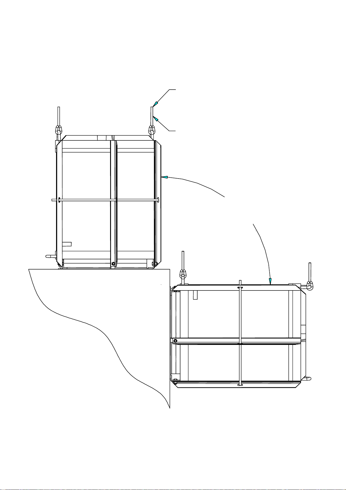
Figure 1 Installation Diagram
FLAMQUENCH II
LIFT RING
EXPLOSION VENT
ID TAG
GASKET
BOLTING PAD
HARDWARE
LIFT RING
LIFT RING
Manual P/N: 8.8520.00.0 Page: 9
Revision : A –October 15, 2001
Figure 2 Installation Orientation
FLAMQUENCH II
SHALL BE MOUNTED
WITHIN 90°OF VERTICAL
SUPPORT TO BE EVALUATED
CABLE SUPPORT
Page: 10 Manual P/N: 8.8520.00.0
Revision : A –October 15, 2001
Figure 3 FlamQuench IISpecifications
8”–40”(DN200 –DN1000) SIZES
(Ref. Tables 2 and 3)
Manual P/N: 8.8520.00.0 Page: 11
Revision : A –October 15, 2001
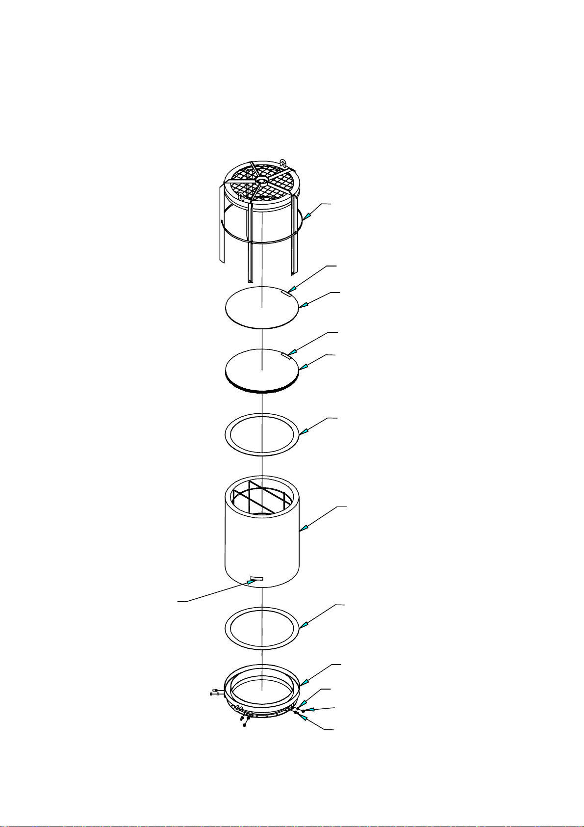
Figure 4 FlamQuench IIAssembly
Sizes 8”–20”(DN200 –DN500)
TOP FRAME WELDMENT
ID TAG
TOP OUTER FILTER
ID TAG
TOP INNER FILTER
FIBER FRAX RING
SIDE FILTER
FIBER FRAX RING
BOTTOM WELDMENT
LOCK WASHER
NUT
BOLT
ID TAG
Page: 12 Manual P/N: 8.8520.00.0
Revision : A –October 15, 2001
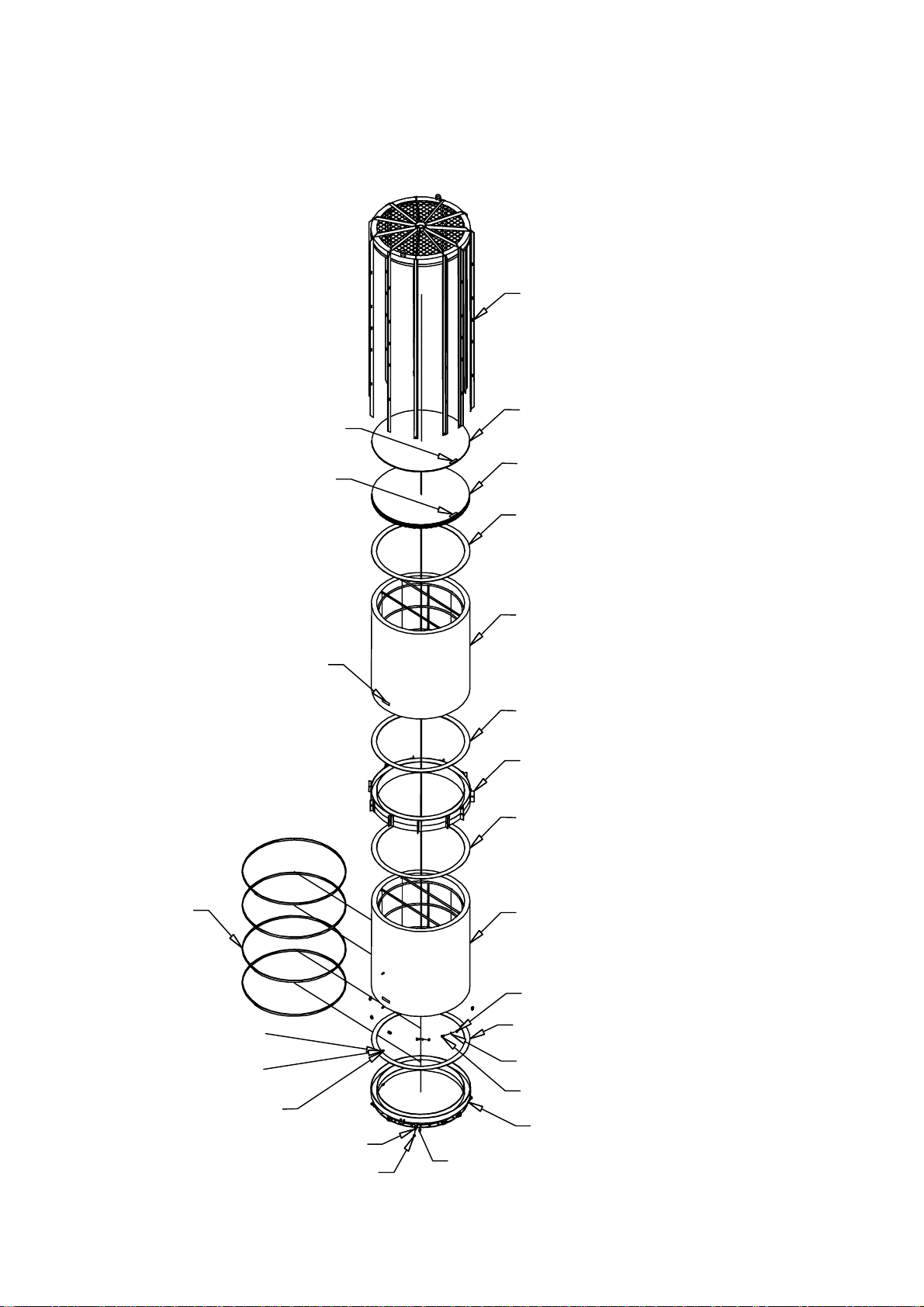
Figure 5 FlamQuench IIAssembly
SIZES 24”–40”(DN600 –DN1000)
TOP FRAME WELDMENT
TOP OUTER FILTER
TOP INNER FILTER
FIBER FRAX RING
ID TAG
ID TAG
SIDE FILTER
ID TAG
FIBER FRAX RING
CENTER RING SUPPORT WELDMENT
FIBER FRAX RING
SIDE FILTER
BAND
NUT
FIBER FRAX RING
LOCK WASHER
BOLT
BOTTOM WELDMENT
BOLT
NUT
LOCK WASHER
BOLT
FLAT WASHER
NYLON LOCK NUT

Manual P/N: 8.8520.00.0 Page: 13
Revision : A –October 15, 2001
Figure 6 Filter Installation
FIGURE 6A
BOTTOM WELDMENT
FIBER FRAX RING
SIDE FILTER
FIGURE 6B
TOP OUTER FILTER
ID TAG
ID TAG TOP INNER FILTER
FIBER FRAX RING
SIDE FILTER
TOP FRAME WELDMENT
HARDWARE
(
STAINLESS
)
FIGURE 6C

Potravinářský průmysl
Farmaceutický průmysl
Biotechnologie
Petrochemie
Chemický průmysl
Energetika
Úprava vody
Papírenství a zpracování celulózy
Plynárenský průmysl
Keramický průmysl
Zpracovatelský průmysl
Firma s tradicí od r. 1990 se při svém vzniku zaměřila na dodávky základních komponent, přístrojové a měřící techniky a dodávky technologií
pro farmaceutický a potravinářský průmysl. Cílem bylo zajistit kompletní dodavatelsko - inženýrské služby, včetně servisu. V roce 1998, který byl pro
rmu velmi významným mezníkem, proběhla transformace společnosti do nynější formy. V dalších letech činnosti společnosti dochází k rozšíření
portfolia a je navazována spolupráce s partnery v oblasti armatur, komponent, ventilů, procesní měřící techniky a čerpadel.
Oblastí působnosti je potravinářský, farmaceutický průmysl, biotechnologie, chemický průmysl, petrochemie, úprava vody, papírenství a
celulóza, energetika, keramický průmysl a zpracovatelský průmysl.
Firma REGOM INSTRUMENTS je díky širokému dodavatelskému portfoliu a bohatým zkušenostem schopna zajistit dodávky armatur,
komponent, čerpadel, přístrojů a zařízení.
Cílem společnosti REGOM INSTRUMENTS je poskytování kvalitních služeb a spolehlivých dodávek pro co nejširší okruh zákazníků.
REGOM INSTRUMENTS s.r.o.
tel.: +420 241 402 206, +420 241 433 152
fax: +420 241 400 290, +420 241 433 151
e-mail: [email protected]
skype: regom-ofce
www.regom.com
flow & process solutions

REGOM INSTRUMENTS s.r.o.
Brabcova 1159 / 2
147 00 Praha 4
CZECH REPUBLIC
Tel: +420 241 402 206
Fax: +420 241 400 290
Skype: regom-office
www.regom.cz
This manual suits for next models
8
Table of contents
Popular Fan manuals by other brands


Sterling
Sterling SE80T quick start guide

UltimateAir
UltimateAir ER80M Manual & Installation Guide

Vortice
Vortice QE 60 LL instructions

Pelonis
Pelonis FS40-16JR owner's manual

Progress Lighting
Progress Lighting AirPro P2586 installation manual

Greenheck
Greenheck XG-5700 Installation, operation and maintenance manual