Fike 403-0006 User manual

This document is only intended to be a guideline and is not applicable to all
situations. Information subject to full disclaimer at www.ke.com/disclaimer
INSTALLATION AND MAINTENANCE
INSTRUCTIONS
Document No. 26-1075 Issue 6
Subject to change
http://www.ke.co.uk/
resource-downloads/addressable/
403-0006 SITA MANUAL CALL POINT
General Description
The Sita Manual Call Point allows for user activation of the re alarm system. Once
operated the device latches into the alarm position and requires manually resetting
via a special key. The MCP is an addressable unit that attaches to the loop. Digital
communication technology to the control panel is implemented allowing for accurate
data transfer at high transmission speeds.
Before Installation
The MCP must be installed in compliance with the control panel installation manual.
The installation must also meet the requirements of any local authority.
Spacing
Fike recommends spacing of call points in accordance with any local authority.
Device Installation
All wiring must be installed in compliance with the recommendations laid out by any local authority as well as any special
recommendations documented in the control panel installation manual. All wiring must be installed in compliance with
the recommendations laid out by any local authority as well as any special recommendations documented in the control
panel installation manual. The cabling used should be of a 2-core 1.5mm2 screened, re resistant type, with the
following characteristics:
Max Capacitance Core to Screen...................................................180pF / m
Max Capacitance Core to Core ......................................................100pF / m
Max Inductance ..............................................................................1.0mH / km
Max Resistance Two Core Screened 1.5mm²................................12.1Ω / km
It is to be wired in the form of a screened 2-core loop returning to the control panel. The use of spurs on this
system is not permitted. Cables may be terminated into the connectors, as shown overleaf. If the device is ush
mounted then the loop cabling must be attached to the device via a suitable connection block (not supplied). Cut o
crimp fork terminals, strip ends for desired length and twist conductor strands together neatly as shown below. Terminate
your cables directly into a ying terminal block. If using a metal back box, do not connect the screen to the back box
earth terminal or allow it to come into contact with the metal box

Document No. 26-1075 Issue 6
Subject to change
Care should be taken when terminating devices to ensure all cables are correctly sleeved and connections are secure.
Improper connections will prevent a system from responding properly in the event of a re.
The Loop +ve (positive) IN and the Loop +ve (positive) OUT connections are split within the module. For cable continuity
readings at the commissioning stage they must be temporarily removed and connected through. Please remember that
all high voltage testing must be carried out before the installation of the electronics, otherwise the electronics will be
damaged. Please also note that the E terminal should only be connected to the loop screen and NOT to the building
earth.
Once all testing has been carried out on the cabling and continuity & insulation has been proven,
the MCP can be connected, with each of the three wires from the MCP front being connected to
the corresponding terminal in the backbox according to the wire colour. The MCP front may then be
installed by locating the upper mounting hook into the receiver in the back box and then pushing the
unit gently home. The single xing screw may then be tightened as required.
NOTE: Before installing the MCP remember to note the serial number of the device (located on the rear of the unit) on
to your drawings or conguration sheets to enable you to prove its location later. The address allocation for the device is
carried out automatically by the control panel whilst in initialisation mode, so addresses do not need to be set manually.
See the system Installation and Operating Instructions for further details.
Reset and Test
The Manual Call Point contains a re-settable element, which latches in position when operated
and does not need to be replaced. Inserting the key as shown and turning it clockwise until the
element clicks back into place will reset the unit. Testing the Call Point may be carried out either
by pressing the element or by using the key in the same manner as for resetting but without
having pressed the element
Technical Data
Dimensions: Width x Height 87mm x 87mm
Depth: Standard inc base 53mm
Depth: Flush mounted 25mm
Flush Back Box Dimensions: Required Minimum Depth 47mm
Operating Temperature: -10oC to +50oC.
Voltage Range (Loop): 24 to 42V DC
LED Indication: Activated 0.3s interval
Flammability UL94-V2
IP Rating IP 21C
System Compatibility: Sita200plus V2.00 onwards.
Duonet and Quadnet V1 onwards.
CIE-A-200 V1 onwards
Terminal Description
R (RED) Loop +ve IN
Y (YELLOW) Loop +ve OUT
B (BLUE) Loop -ve IN & OUT
ELoop SCREEN IN & OUT
E
BLUE RED
YELLOW
Y
B R
Fike Safety Technology Ltd
Unit 31, Springvale Industrial Estate
Cwmbran
NP44 5BD
Tel: 01633 865 558 | Email: fstinfo@ke.com Document No. 26-1075 Issue 6
Subject to change
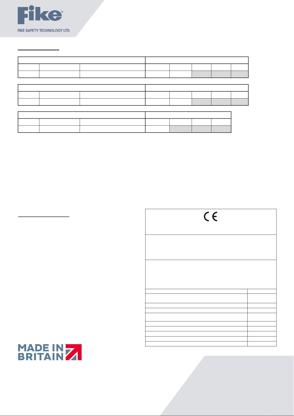
2831
Fike Safety Technology Ltd
Unit 31, Springvale Ind. Est.
Torfaen, NP44 5BD
11
DoP-403-0006
EN54-11: 2001 +A1: 2005, EN54-17: 2005
Isolator Technical Data: See 26-1112
403-0006
Intended for use in the re detection and re alarm
Systems in and around buildings
Essential characteristics Performance
Nominal activation conditions/Sensitivity, response delay (response time)
and performance under re conditions Pass
Operational reliability Pass
Tolerance to supply voltage Pass
Durability of operational reliability and response delay, Temperature
resistance Pass
Durability of operational reliability, Vibration resistance Pass
Durability of operational reliability, Humidity resistance Pass
Durability of operational reliability, Corrosion resistance Pass
Durability of operational reliability, Electrical stability Pass
Performance under re conditions Pass
Technical Support
Contact your supplier for technical support on this
product.
Due to the complexity and inherent importance of
a life risk type system training on this equipment is
essential, and commissioning should only be carried
out by competent persons. Fike cannot guarantee the
operation of any equipment unless all documented
instructions are complied with, without variation.
Fike’s policy is one of continual improvement and the
right to change a specication at any time without
notice is reserved. Whilst every care has been taken to
ensure that the contents of this document are correct
at time of publication, Fike shall be under no liability
whatsoever in respect of such contents. E&OE
Technical Data
PRODUCT DESCRIPTION LOOP CURRENT (mA)
Type Product Code Name Quiescent Alarm Low Medium High
MCP 403 0006 Sita Manual Call Point Mk3 0.18 2.89 - - -
BATTERY CURRENT (mA)
Type Product Code Name Quiescent Alarm Low Medium High
MCP 403 0006 Sita Manual Call Point Mk3 0.18 6.00 - - -
DLU RATING
Type Product Code Name Alarm Low Medium High
MCP 403 0006 Sita Manual Call Point Mk3 3 - - -
Other Fike Firefighting Equipment manuals

Popular Firefighting Equipment manuals by other brands

Grundfos
Grundfos Hydro EN Safety instructions and other important information

Tyco
Tyco 802SB installation instructions

Waterous
Waterous AQUIS Series Installation, operation and maintenance instructions

TFT
TFT EXTEND-A-GUN XG12 Instructions for installation, safe operation and maintenance

Tyco Fire Suppression & Building Products
Tyco Fire Suppression & Building Products ANSUL AQUASONIC Design, Installation, Recharge, and Maintenance Manual

Tyco
Tyco EC-11 Series quick guide

