Tyco Fire Suppression & Building Products ANSUL AQUASONIC User manual

AQUASONIC PRE-ENGINEERED WATER-
ATOMIZING FIRE SUPPRESSION SYSTEM
Design, Installation, Recharge, and Maintenance Manual
(Label No. F-2010225)


This manual is intended for use with the ANSUL AQUASONIC Pre-
Engineered Water-Atomizing Fire Suppression System.
Those who install, operate, recharge, or maintain this fire suppres-
sion system should read this entire manual. Specific sections will
be of particular interest depending upon one’s responsibilities.
Design, installation, recharge, and maintenance of the system
must conform to the limitations detailed in this manual and must be
performed by an individual who attended an ANSUL training
program and is trained to install, recharge, design, and maintain
the ANSUL system.
Fire suppression systems are mechanical devices that require
periodic care. Inspection and maintenance are vital steps in the
performance of your fire suppression system. As such, they must
be performed by an authorized ANSUL distributor in accordance
with this manual as well as NFPA 750 "Standard on Water Mist
Fire Protection Systems" or equivalent national or international
standards. An inspection will provide reasonable assurance that
the fire suppression system is fully charged and operable, and will
vary in frequency from hourly to monthly, based on the needs of
the situation. To provide maximum assurance that the fire suppres-
sion system will operate effectively and safely, maintenance must
be conducted at six-month intervals, or earlier if the situation
dictates.
ANSUL Part No. 435650-03

REVISION RECORD
7-19-10
REV. 3
6-1-09 16 1
6-1-09 18 1
6-1-09 Appendix A New
6-1-09 Appendix B New
12-30-09 1 2
12-30-09 2 2
12-30-09 3 2
12-30-09 4 2
12-30-09 5 2
12-30-09 6 2
12-30-09 7 2
12-30-09 8 2
12-30-09 9 2
12-30-09 10 2
12-30-09 11 2
12-30-09 12 1
12-30-09 13 2
12-30-09 14 1
12-30-09 17 1
12-30-09 19 2
12-30-09 20 2
12-30-09 21 1
12-30-09 24 1
12-30-09 26 1
12-30-09 27 1
12-30-09 28 1
12-30-09 29 1
7-19-10 Complete manual has 3
been reformatted plus
technical changes have
been made. For clarity, all
pages have been
changed to Revision 3
regardless of previous
revision number. Technical
information changes have
been noted with a revision
indicator ( ).
DATE PAGE REV. NO. DATE PAGE REV. NO.
Indicates revised information.
Indicates no change to text – change in page sequence only.
LEGEND FOR MANUAL PAGE
REVISION INDICATORS:

SECTION PAGE NO.
________ _________
COMPONENTS 1 – 17
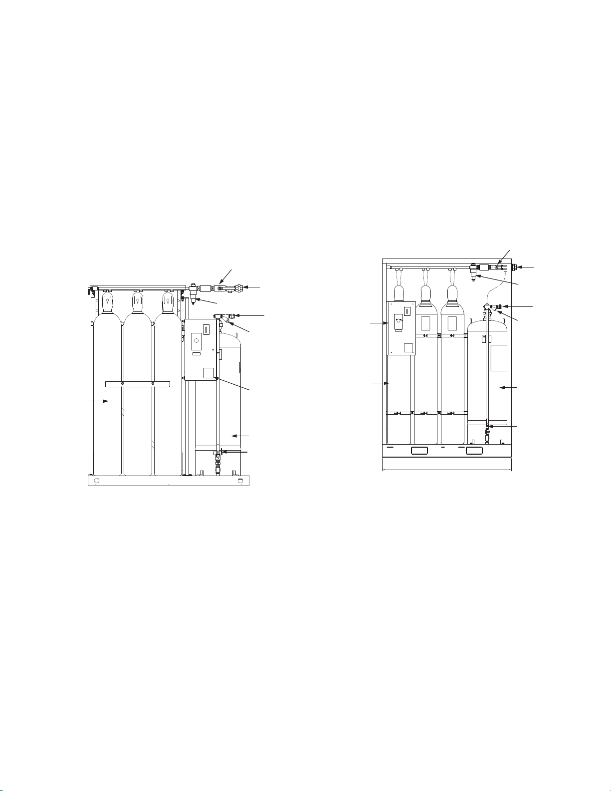
Complete ASME and DOT Approved 1
AQUASONIC Skid Assembly
Complete TPED and CE Marked 1
AQUASONIC Skid Assembly
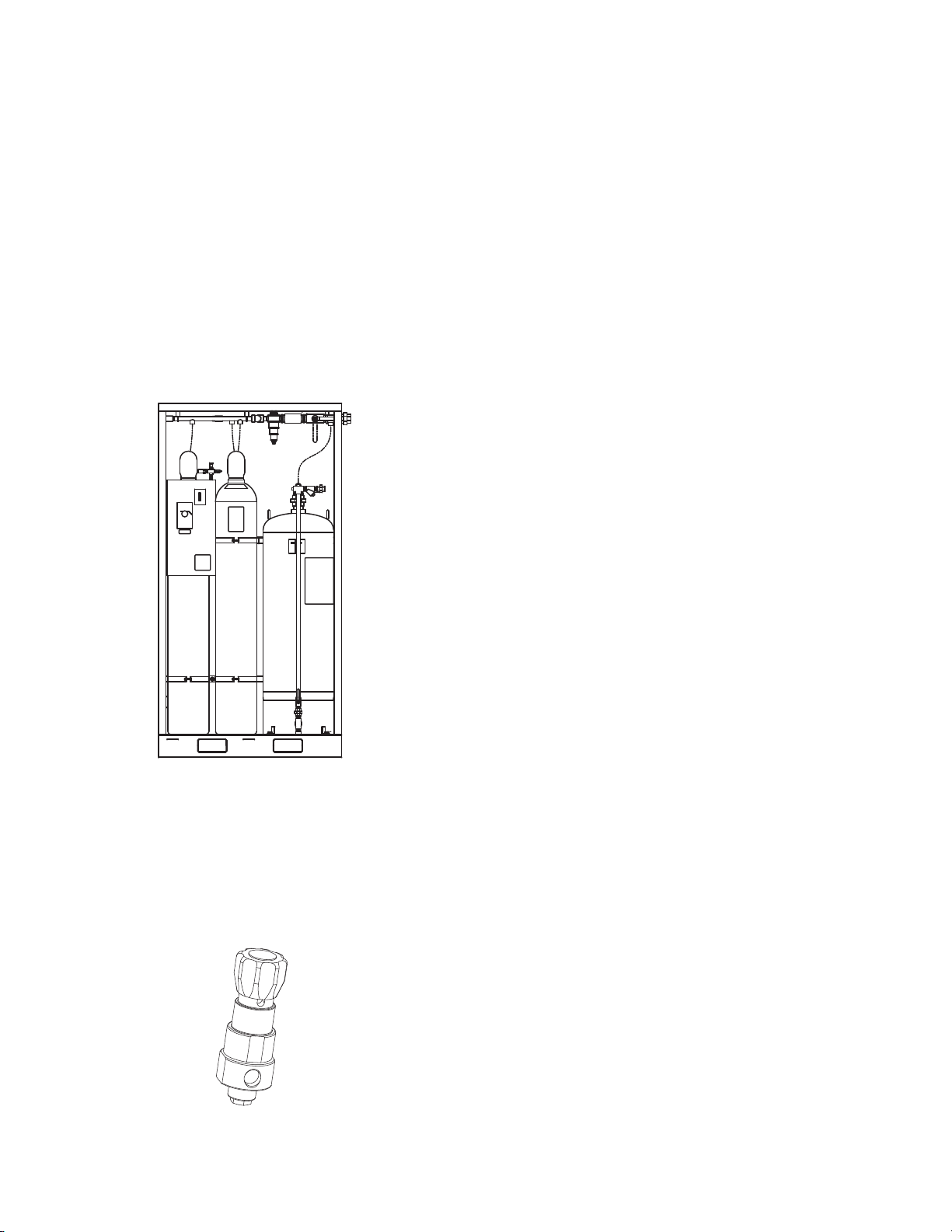
Complete TPED and CE Marked 2
AQUASONIC 130 m3Skid Assembly
Regulator 2
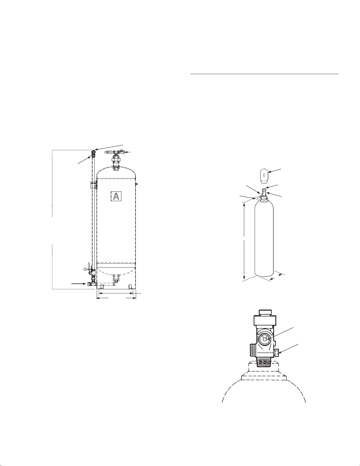
50 US Gallon (189.3 L) Water Tank Assembly 3
CV-98 Valve / Cylinder Shipping Assembly 3
CV-98 Valve 3
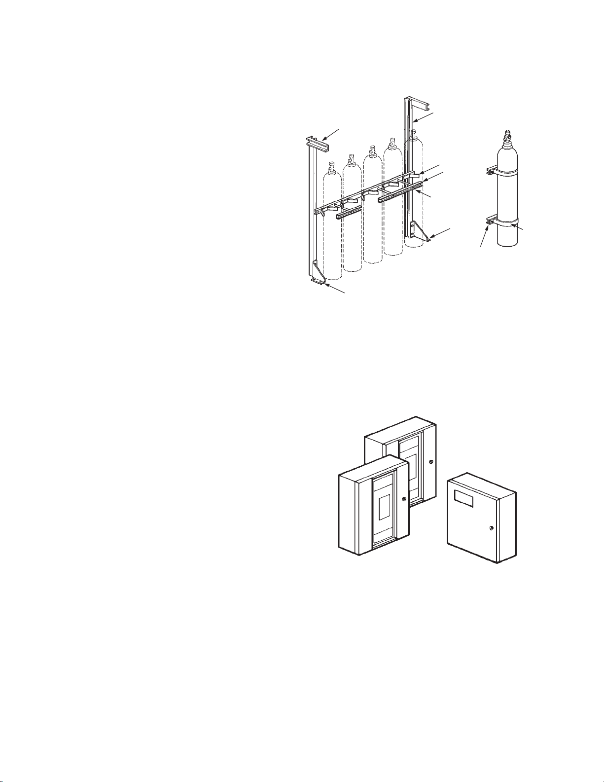
Cylinder Bracketing 4
AUTOPULSE Control System 4
ANSUL AUTOMAN II-C Releasing Device 5
Remote Actuator (Optional) 5
Booster Actuator 6
HF Electric Actuator 6
Lever Release Actuator 6 – 7
Flexible Discharge Bend 7
Water Tank Pressurization Hose and Fitting 7
Header Vent Plug 7
Header Safety Burst Disc 8
Actuation Components 8
Check Valves 8
Relief Valve 9
Vent Poppet 9
Pressure Switch – DPST 9
Pressure Switch – DPDT – Explosion-Proof 10
Pressure Switch – 3PST 10 – 11
Pressure Trip 11
Nitrogen Discharge Relief Valve 11
System Shut-Off Valves 12
Atomizer 12
Pneumatic Selector Valve 12 – 13
Electric Selector Valves 13
Nameplate – AQUASONIC System (US) 14
Nameplate – AQUASONIC System (EMEA) 14
Nameplate – MAIN 14
Nameplate – RESERVE 14
Warning Plate – Inside Room With Alarm 5
Warning Plate – Outside Room Without Alarm 15
Pressure Test Assembly 15
Check Valves 16
GENERAL INFORMATION 17 – 22
Spray Characteristics 17
Approvals 17 – 18
Typical Operation Sequence 18
Types of Actuation 18
Electrical 18
Mechanical 18
Pneumatic 18
Types of Detection 18
Electronic Control Panel 18
Electric Releasing Device 18
SECTION PAGE NO.
________ _________
System Limitations 18 – 21
AQUASONIC Atomizer 19
Pendent (Downward) Position Parameters 19
Sidewall Position Parameters 19
Application of Pendent Constraints 20
Application of Sidewall Constraints 21
Control of Run-Off 22
Ventilation and Leakage 22
Relief Venting 22
PLANNING 23 – 24
Initial General Information 23
Hazard Information 23
Supply Requirements 23
Atomizer Placement Requirements 23
Actuation and Alarm Requirements 23
DESIGN 25 – 30
Step No. 1 – Determine the Floor Area and 25
Gross Volume of the Room
Step No. 2 – Determine the Minimum Number 25
of Atomizers Required
Step No. 3 – Verify Atomizer Array Placement 25
Step No. 4 – Determine Location of System Supply 25
Step No. 5 – Sketch Pipe Routing 26
Water Calculation Procedure 26 – 28
Step No. 6 – Determine Volume of Water 27
Supply Required
Step No. 7 – Determine Number of Water 27
Tanks Required
Step No. 8 – Determine Total Atomizer Pressure 27 – 28
(TAP)
Step No. 9 – Select Appropriate 28
Atomizer Assembly
Nitrogen Calculation Procedure 29 – 30
Step No. 10 – Determine Atomizer Pressure Loss 30
Step No. 11 – Determine the Number of 30
Nitrogen Cylinders
Step No. 12 – Complete Layout of the System 30
Step No. 13 – Create a Bill of Materials 30
Step No. 14 – Create Installation Drawings 30
INSTALLATION 31 – 40
General Information 31
Pre-Assembled Supply Skid Installation 31
Nitrogen Cylinder Installation 31 – 34
Bracketing without Uprights – Double Row 32
Bracketing with Uprights – Back-to-Back 32
Bracketing with Uprights – 33
Double Row Back-to Back
Water Tank Installation 34
Atomizer Installation 34
Releasing Devices 35
General Piping Requirements 35
Pipe Assembly 35
Hanger Requirements 35
TABLE OF CONTENTS
7-19-10 Page 1
REV. 3

SECTION PAGE NO.
________ _________
INSTALLATION (Continued) 31 – 40
Actuation Piping 35 – 36
Installation of Actuation Piping 36
High Pressure Manifold and Regulator 36
High Pressure Pipe and Fitting Requirements 36
Installation of High Pressure Manifold 36
and Regulators
Discharge Piping (After Regulators) 37 – 38
System Pipe, Tubing, and Fitting Requirements 37
Installation of Nitrogen Discharge Piping 37
Installation of Water Tank Pressurization Piping 37
Installation of Water Discharge Piping 38
Installing Detection/Actuation System 38
AUTOPLUSE System with Electric Actuator 38
AUTOPULSE System with 38
ANSUL AUTOMAN II-C with Pneumatic Actuation
Installing Actuator 39 – 40
Pneumatic Actuation for CV-98 Valve 39
Electric Actuator 39
Installing the Booster Actuator 39
Installing the HF Actuator 39
Wiring for HF Actuator to AUTOPLUSE 39
Control Panel
Stacking Actuators 39
Installing Remote Pneumatic Actuators 40
Electric Pull Station to AUTOPULSE Control Panel 40
Installing Accessories 40
Alarms 40
Pressure Trip 40
Pressure Switch 40
Ventilation 40
Fill Water Tanks 40
INSPECTION 41 – 42
MAINTENANCE 43 – 46
RESETTING AND RECHARGE 47 – 50
Clear Electrical Equipment 47
Check Electrical and Mechanical Equipment 47
Piping and Atomizers 47
Selector Valves 47
Electric Detection Systems 47
Pressure Switch 47
Place System Back in Service 48
Recharge Water Tank 48
Recharge Nitrogen Cylinders 48 – 49
Remote Pneumatic Actuation 49
Lever Actuator 49
Electric Manual Pull Station 49
Resetting the HF Actuator 49
Resetting the Booster Actuator 49
SECTION PAGE NO.
________ _________
APPENDIX A – ATOMIZER PLACEMENT 51 – 52
AND OBSTRUCTIONS
Discharge Path 51
Obstruction Allowances 51 – 52
Sample Calculation Procedure 52
APPENDIX B – SELECTOR VALVES 53 – 59
APPENDIX C – MAIN AND RESERVE 61 – 62
TABLE OF CONTENTS
7-19-10 Page 2
REV. 3

COMPLETE ASME AND DOT APPROVED
AQUASONIC SKID 260 m3ASSEMBLY
The AQUASONIC Skid Assembly is a self-contained assembly
consisting of a 50 US gal (189.3 L) water tank, six 575 ft3
(16.3 m3) regulated nitrogen cylinders, and the necessary valving
for tank blow-down. Components are fabricated on a rugged skid
assembly that is painted with a red, air dry enamel finish. The
assembly is compact and can be easily positioned in any desired
location.
ANSUL AUTOMAN II-C Release (Part No. 17728) comes stan-
dard on skid assembly. AUTOMAN II-C Explosion/Weather-Proof
Release (Part No. 35623) may be substituted at time of order by
specifying assembly as well as bracket Part No. 436285.
Part No. 437665
FIGURE 1
008454
COMPLETE TPED AND CE MARKED AQUASONIC 260 m3
SKID ASSEMBLY
The AQUASONIC Skid Assembly is a self-contained assembly
consisting of a 50 US gal (189.3 L) water tank, six 561 ft3(16 m3)
regulated nitrogen cylinders, and the necessary valving for tank
blow-down. Components are fabricated on a rugged skid assem-
bly. The assembly is compact and can be easily positioned in any
desired location. Must specify ANSUL AUTOMAN II-C Release
(Part No. 17728) or AUTOMAN II-C Explosion/Weather-Proof
Release (Part No. 35623).
Part No. 303.211.001
FIGURE 2
008455
COMPONENTS
7-19-10 Page 1
REV. 3
ANSUL AUTOMAN
II-C RELEASING
DEVICE OR
AUTOMAN II-C
EXPLOSION-
PROOF RELEAS-
ING DEVICE
2900 PSI
(200 BAR)
NITROGEN
CYLINDERS
WITH CV-98
VALVES
WATER LINE
SHUT-OFF VALVE
(BLACK)
HEIGHT: 78 IN (198 cm)
WIDTH: 35 IN (89 cm)
LENGTH: 64 IN (162 cm)
WEIGHT: 3352 LB (1516 kg)
WATER TANK
WATER
SUPPLY “Y”
STRAINER
NITROGEN
OUTLET
NITROGEN LINE
SHUT-OFF VALVE (RED)
WATER
OUTLET
HIGH FLOW REGULATOR
1500
2900 PSI
(200 BAR)
NITROGEN
CYLINDERS
WITH CV-98
VALVES
WATER LINE
SHUT-OFF VALVE
(BLACK)
HEIGHT: 90.5 IN (2300 mm)
WIDTH: 31.5 IN (800 mm)
LENGTH: 59 IN (1500 mm)
WEIGHT: 1984 LB (900 kg)
WATER TANK
WATER
SUPPLY “Y”
STRAINER
ANSUL
AUTOMAN II-C
RELEASING
DEVICE OR
AUTOMAN II-C
EXPLOSION-
PROOF
RELEASING
DEVICE
NITROGEN
OUTLET
NITROGEN LINE
SHUT-OFF VALVE (RED)
WATER
OUTLET
HIGH FLOW
REGULATOR

COMPLETE TPED AND CE MARKED AQUASONIC 130 m3
SKID ASSEMBLY
The AQUASONIC Skid Assembly is a self-contained assembly
consisting of a 50 US gal (189.3 L) water tank, three 561 ft3
(16 m3) regulated nitrogen cylinders, and the necessary valving for
tank blow-down. Components are fabricated on a rugged skid
assembly.
The assembly is compact and can be easily positioned in any
desired location. Must specify ANSUL AUTOMAN II-C Release
(Part No. 17728) or AUTOMAN II-C Explosion/Weather-Proof
Release (Part No. 35623).
Part No. 303.211.002
FIGURE 3
008594
REGULATOR
The AQUASONIC Skid Assembly contains one high-flow regulator.
The regulator is factory set to provide a delivery pressure of 125
psi (8.3 bar), allowing the proper nitrogen pressure to discharge
the water from the tank to the atomizer. It also allows the neces-
sary nitrogen pressure to flow directly to the atomizer to activate
its advanced atomization technology.
Part No. 436987
FIGURE 4
008451
COMPONENTS
7-19-10 Page 2
REV. 3
HEIGHT: 90.5 IN (2300 MM)
WIDTH: 29.5 IN (750 MM)
LENGTH: 46.8 IN (1190 MM)
WEIGHT: 1276 LB (580 KG)

50 US GALLON (189.3 L) WATER TANK ASSEMBLY
The AQUASONIC System agent tank is a 50 US gal (189 L)
capacity water tank featuring a 0.17 in. (4.3 mm) thick ASME pres-
sure vessel that is certified to 150 psi (14.8 bar). This vessel is
both ASME and 97/23/EC (PED) CE marked. The tank features a
2 in. (5.1 cm) fill opening; the tank also has an outlet that is posi-
tioned for optimal flow, containing a Y strainer which will reduce the
number of foreign particles in the water stream reaching the atom-
izers. The tank is constructed from 304L stainless material to help
ensure rust-free performance.
Note: Mounting feet will accept up to a 1/2 in. (12 mm) diameter
bolt.
Part No. 435764
FIGURE 5
CV-98 VALVE / CYLINDER SHIPPING ASSEMBLY
The cylinder is factory filled with nitrogen to a nominal pressure of
2900 psi (200 bar). Multiple cylinders can be manifolded together
to obtain the required quantity of nitrogen. The cylinder valve can
be actuated electrically, pneumatically, and/or manually with
approved valve actuation components. All valves are equipped
with an anti-recoil feature.
The cylinders are shipped with a maintenance record card and
protective shipping cap attached to the threaded neck of each
cylinder. This cap entirely encloses and protects the valve while in
shipment.
Component Material Approvals
__________ _______ _________
Cylinder Steel Meets DOT 3AA3000 or
EN1964-2
Valve Brass
Safety Relief Valve Brass
Valve/Cylinder — FM Approved
Assembly
Shipping Cap Steel
Standardized
Shipping Cylinder Approximate Amount Dimension Dimension
Assembly N2Capacity Weight of N2AB
Part No. ft3(m3) lb (kg) lb (kg) in. (cm) in. (cm)
DOT 437166 575 (16.3) 322 (146) 41.1(18.6) 68.5 (174.0) 11.0 (27.9)
TPED 21741 561 (16.0) 229 (104) 40.0(18.2) 68.0 (172.7) 10.5 (26.7)
CV-98 VALVE
The CV-98 valve has a ten year warranty. The valve requires no
internal maintenance. The valve is sealed closed and must not
be disassembled. If there is ever a malfunction of the CV-98 valve,
the complete valve must be sent back to ANSUL for warranty
replacement. If the external seal is broken, the warranty is
voided.
Note: Use Flexible Discharge Bend, Part No. 427082, when attaching
valve to supply pipe or manifold.
FIGURE 6
002251
FIGURE 7
002252
COMPONENTS
7-19-10 Page 3
REV. 3
008471
“Y”
STRAINER
FILL/
PRESSURIZATION
PORT
WATER LINE
SHUT-OFF
VALVE
(BLACK)
HEIGHT TO
CENTER OF
PIPE
CONNECTION
63.5 IN. (1.61 m)
DISCHARGE
PORT
14.5 IN. (0.37 m)
SQUARE
PATTERN FOR
MOUNTING
FEET
18” OD
VALVE
HEIGHT TO OUTLET
CENTER
RECORD
TAG
PRESSURE
GAUGE
CYLINDER
SHIPPING CAP
VALVE SHIPPING CAP
B
A
PRESSURE
GAUGE
SAFETY
RELIEF
VALVE

CYLINDER BRACKETING
The cylinder bracketing is designed to rigidly support the installed
nitrogen agent cylinders. The bracketing components are
constructed of heavy structural steel. Bracket assemblies are
available in modules for two to six cylinders and can also be
connected together for any combination over six. Bracketing can
be assembled to support single row, double row or back-to-back
rows of cylinders. Bracketing components are painted with a red
enamel coating. Uprights and back frame assemblies can be
bolted or welded together, whichever makes the installation more
convenient.
Component Material Approvals
__________ _______ _________
Bracketing Steel FM Approved
Shipping
Assembly
Part No. Description
_______ __________
45122 575 ft3(16.3 m3) cylinder strap (single cylinder)
45245 575 ft3(16.3 m3) cylinder channel with nuts and
bolts (single cylinder)
79638 Back frame assembly (2 cylinder)
79639 Back frame assembly (3 cylinder)
79640 Back frame assembly (4 cylinder)
79641 Back frame assembly (5 cylinder)
79642 Back frame assembly (6 cylinder)
73257 Upright, for 575 ft3(16.3 m3) cylinders (used either
for right side, left side or center (center upright
required when connecting seven or more cylinders in
a row))
73553 Single row or back-to-back row bracket foot (left
side)
73554 Single row or back-to-back row bracket foot (right
side)
73555 Double row bracket foot (left side)
73556 Double row bracket foot (right side)
418508 Center upright foot
79413 Connector (required to hook together back frames
for seven or more cylinders)
418502 13 in. (33.0 cm) carriage bolt with nut (for single row
575 ft3(16.3 m3) cylinders)
418503 27 in. (68.6 cm) carriage bolt with nut (for double
row 575 ft3(16.3 m3) cylinders)
73091 Cylinder clamp (2 cylinders)
73092 Cylinder clamp (3 cylinders)
71683 Weigh rail support – single row
71682 Weigh rail support – double row
71684 Weigh rail support – back-to-back rows
423027 Weigh rail support – back-to-back double row
FIGURE 8
AUTOPULSE CONTROL SYSTEM
The AUTOPULSE Control System provides a range of features
and benefits, ranging from simple detection through counting
circuits.
Several models of the AUTOPULSE Control System are available
depending on the type of hazard being protected.
Refer to the ANSUL Detection and Control Application Manual for
detailed information concerning all AUTOPULSE Control Systems.
FIGURE 9
002195
COMPONENTS
7-19-10 Page 4
REV. 3
Multi-Cylinder Single Cylinder
UPRIGHT
BACK FRAME
CYLINDER
CLAMP
CARRIAGE BOLT
WITH NUT
RIGHT
BRACKET
FOOT
LEFT
BRACKET FOOT
CHANNEL 002200
CLAMP
WEIGH
RAIL SUPPORT

ANSUL AUTOMAN II-C RELEASING DEVICE
The ANSUL AUTOMAN II-C Releasing Device consists of a metal
enclosure which contains a spring-loaded puncture pin release
mechanism, actuation cartridge, electrical circuitry, and an
input/output terminal strip for making electrical connections. The
ANSUL AUTOMAN II-C Releasing Device provides automatic
pneumatic actuation of the AQUASONIC System. When wired to
an AUTOPULSE Control System, it will provide supervised electric
detection and release. The ANSUL AUTOMAN II-C Releasing
Device also provides manual actuation using the strike button on
the release enclosure or with the optional remote manual cable
pull station. When an AUTOPULSE Control System is used,
manual actuation is accomplished using an electric manual pull
station.
The ANSUL AUTOMAN II-C Releasing Device requires an LT-
10-R nitrogen cartridge for system actuation. Cartridge must be
ordered separately.
Part No. Description
______ _________
17728 ANSUL AUTOMAN II-C Releasing Device Shipping
Assembly
35623 ANSUL AUTOMAN II-C Explosion/Weather-Proof
Releasing Device Shipping Assembly (24 VDC)
32525 ANSUL AUTOMAN II-C Explosion/
Weather-Proof Releasing Device Shipping Assembly
(120 VAC)
32526 ANSUL AUTOMAN II-C Explosion/
Weather-Proof Releasing Device Shipping Assembly
(240 VAC)
423423 LT-10-R Nitrogen Cartridge Shipping Assembly
(order separately)
428449 TPED Approved LT-10-R Nitrogen Cartridge
Shipping Assembly (order separately)
423435 LT-30-R Nitrogen Cartridge Shipping Assembly
(order separately)
428441 TPED Approved LT-30-R Nitrogen Cartridge
Shipping Assembly (order separately)
26310 Cocking Lever (order separately)
435852 ANSUL AUTOMAN II-C Releasing Device Mounting
Bracket
436285 ANSUL AUTOMAN II-C Explosion/Weather-Proof
Releasing Device Mounting Bracket
FIGURE 10
000442
REMOTE ACTUATOR (OPTIONAL)
The remote actuator is a device that allows for system actuation
from a location either near or far from the AQUASONIC System
Supply. Two types of actuators are offered. One requires an LT-10-
R nitrogen cartridge, and the other requires an LT-30-R nitrogen
cartridge. When actuated, the cartridges will supply pressure to
the CV-98 valve pilot actuation port on the pilot cylinder, allowing
nitrogen to flow. Cartridge must be ordered separately.
Part No. Description
_______ __________
32743 Remote Actuator Shipping Assembly – LT-10-R
32746 Remote Actuator Shipping Assembly – LT-30-R
423423 LT-10-R Nitrogen Cartridge Shipping Assembly
(order separately)
428449 TPED Approved LT-10-R Nitrogen Cartridge
Shipping Asembly (order separately)
423435 LT-30-R Nitrogen Cartridge Shipping Assembly
(order separately)
428441 TPED Approved LT-30-R Nitrogen Cartridge
Shipping Assembly (order separately)
Maximum Combined Length of Actuation Piping
1/4 in. 1/4 in. Stainless Steel
Cartridge Schedule 40 Piping Tubing (0.028 in. wall)
________ ________________ _________________
LT-10-R 50 ft (15 m) 150 ft (46 m)
LT-30-R 150 ft (46 m) 450 ft (137 m)
FIGURE 11
008463
COMPONENTS
7-19-10 Page 5
REV. 3
LT-10-R
CARTRIDGE

BOOSTER ACTUATOR
The Booster Actuator, Part No. 428949, is used when electric actu-
ation is required on the 1 in. selector valve, 2 in. selector valve, or
the CV-98 cylinder valve. The actuator mounts directly to the
component and then an HF electric actuator mounts to the top of
the booster actuator.
The Booster Actuator requires resetting after actuation. A Reset
Tool, Part No. 429847, is available for this use.
Component Material Approvals
_________ _______ _________
Booster Stainless Steel FM Approved
Actuator and Brass
FIGURE 12
HF ELECTRIC ACTUATOR
Electrical actuation is accomplished by an HF electric Actuator,
Part No. 73327, interfaced through an AUTOPULSE Control
System. This actuator can be used in hazardous, indoor environ-
ments where the ambient temperature range is between 0 °F to
130 °F (–18 °C to 54 °C). The HF electric actuator meets the
requirements of N.E.C. Class I, Div. 1, Groups B, C, D and Class
II, Div. 1, Groups E, F, G. A maximum of two HF electric actuators
can be used on a single AUTOPULSE release circuit. When utiliz-
ing only one HF electric actuator, an in-line resistor, Part No.
73606, is required in the supervised release circuit.
In auxiliary or override applications, a manual-local override valve
actuator or a manual cable pull actuator can be installed on top of
the HF electric actuator by removing the safety cap.
An arming tool, Part No. 75433, is required to reset the actuator
after operation. The actuator contains a standard 1/2 in. threaded
female straight connector for electrical conduit hookup.
Technical Information
Nominal Voltage: . . . . . . . . . . . . . . . . . . . . 12 VDC @ 0.57 amps
Rated Voltage:
Minimum:. . . . . . . . . . . . . . . . . . . . . . . . . . . . . . . . . 12.0 VDC
Maximum: . . . . . . . . . . . . . . . . . . . . . . . . . . . . . . . . 14.0 VDC
Thread Size/Type: . . . . . . . . . . . . . . . . 1/2 in. straight female for
electrical conduit hookup
Material:
Body:. . . . . . . . . . . . . . . . . . . . . . . . . . . . . . . . . . . . . . . . . Brass
Plunger: . . . . . . . . . . . . . . . . . . . . . . . . . . . . . . . Stainless Steel
FM Approved
FIGURE 13
006361
LEVER RELEASE ACTUATOR
The manual lever release actuator provides a manual means of
actuating cylinder valves and selector valves. This can be accom-
plished by direct manual actuation of its pull lever or cable actua-
tion when used in conjunction with a remote manual pull station.
When used with a remote manual pull station, the pull station must
contain the components necessary to meet the actuator lever trav-
eling requirements of 7 in. (178 mm).
The actuator is shipped with ring pin and chain attached. If the ring
pin is not required, it must be removed. Failure to remove the ring
pin/chain assembly will prevent system actuation if a remote cable
pull actuation system is employed and the ring pin is accidentally
installed in the actuator.
Four actuators are available. Each is designed for a specific
component.
Note: For use with systems without selector valves.
Component Material Approvals
_________ _______ _________
All Manual Brass with UL Listed
Cable-pull Stainless Steel Pin FM Approved
Actuators
Shipping
Assembly
Part No. Description
______ _________
423309 Lever Release (1 1/8-18 mounting thread) – Mounts
directly to a CV-98 cylinder valve for service and
installation only. Do not use for actuation in final
system configuration.
70846 Lever Release (1 1/4-18 mounting thread) – Mounts
directly to an HF electric actuator.
COMPONENTS
7-19-10 Page 6
REV. 3
006037
Ø 2.50
3.025
1 1/4 – 18 UNEF
1 1/8 – 18 UNEF
4 1/2 IN.
(114 mm)
2 1/4 IN.
(57 mm)
1 1/4 – 18
1 1/4 – 18

LEVER RELEASE ACTUATOR (Continued)
FIGURE 14
FLEXIBLE DISCHARGE BEND
The valve Flexible Discharge Bend (Part No. 427082) is a 5/8 in.
(1.59 cm) ID extra-heavy flexible hose which connects the valve
discharge outlet to the fixed piping or header manifold. The
discharge bend has a special female thread for connecting to the
valve outlet and a male 1/2 in. NPT thread for connecting to the
fixed piping or manifold. The discharge bend will withstand a pres-
sure of 9000 psi (621 bar). Its flexible connection allows for easy
alignment of multiple cylinder banks to fixed piping. Each bend has
a built-in check valve that prevents loss of agent should the system
discharge while any cylinder is removed.
The equivalent length of this hose is equal to 18 ft (5.5 m) of 1/2
in. Schedule 40 pipe.
Shipping Assembly
Part No. Description
_______ __________
427082 Flexible discharge bend
42430 Washer
Thread Size/Type
Component Material Valve End Manifold End Approvals
5/8 in. Flexible SAE 100 Special to 1/2 in. UL Listed
Discharge Bend R2 mate with NPT Male (EX-4510)
Type AT CV-98 Valve FM
Approved
FIGURE 15
000658
WATER TANK PRESSURIZATION HOSE AND FITTING
The water tank pressurization hose (Part No. 72584) is a 1/2 in.
diameter flexible hose which connects the water tank to the regu-
lated water tank pressurization piping. This allows for easy
removal of the water tank fill connection for tank inspection and
filling.
The swivel adaptor (Part No. 25582) provides a swivel connection
which allows installation of the hose without twisting the hose.
FIGURE 16
008472
Part No. 25582 – Swivel Adapter Union
FIGURE 17
008473
HEADER VENT PLUG
The header vent plug is used to release low pressure build- up that
may occur in a closed system. The header vent plug must be
installed on every high pressure manifold where cylinders are
connected. The header vent plug must be installed on the cylinder
sides of the check valves on both main and reserve systems to
relieve any pressure that may leak past the check valve and acci-
dentally actuate the reserve system while the main system is
discharging.
Shipping Assembly
Part No. Description
_______ __________
437353 Header vent plug
Component Material Thread Size/Type Approvals
__________ _______ _______________ _________
Vent Plug Body: 1/4 in. NPT Male FM Approved
Brass
Spring:
Bronze
Seal:
Neoprene
FIGURE 18
COMPONENTS
7-19-10 Page 7
REV. 3
3 7/8 IN.
(9.8 cm)
DEPTH: 3 7/8 IN. (7.6 cm)
3 7/8 IN.*
(9.8 cm)
000897
* Add 1 9/16 in. (3.9 cm) to height when lever is in the straight up position.
PIN
18 7/8 IN.
(47.9 cm)
MANIFOLD/
END
1/2 IN. NPT
MALE COUPLING
FEMALE ADAPTOR
(BRASS)
VALVE
END
CHECK
WASHER
SWAGE ON
Part No. 72584 – Hose Assembly
008485
1.69 IN.
(43 mm)
1.50 IN.
(38 mm)
0.71 IN.
(18 mm)

HEADER SAFETY BURST DISC
The manifold relief valve is used to release high pressure build-up
that may occur in a closed system.
A manifold relief valve must be installed on every high pressure
manifold where cylinders are connected and on every manifold
isolated by a selector valve or check valve.
Internal safety disc will rupture between 4000-4480 psi (276-309
bar).
Shipping Assembly
Part No. Description
_______ __________
437218 Manifold Relief Valve
Component Material Thread Size/Type Approvals
__________ _______ _______________ _________
Manifold Body: 1/2 in. NPT Male FM Approved
Relief Valve Brass CE Approved
FIGURE 19
ACTUATION COMPONENTS
The Stainless Steel Actuation Hose is used to connect the actua-
tion line flared tees between each agent tank. The hose has the
same thread, 7/16-20, as the flared tees. The actuation hose
allows flexibility between the rigid actuation piping and the tank
valve.
Shipping
Assembly
Part No. Description
_______ __________
31809 Stainless Steel Braided Hose, 16 in. (40.6 cm)
Female-to-Female
32335 Stainless Steel Braided Hose, 20 in. (50.8 cm)
Female-to-Female
32336 Stainless Steel Braided Hose, 24 in. (60.9 cm)
Female-to-Female
73596 Stainless Steel Braided Hose, 12 in. (30.5 cm)
Male-to-Female
73597 Stainless Steel Braided Hose, 16 in. (40.6 cm)
Male-to-Female
73598 Stainless Steel Braided Hose, 20 in. (60.9 cm)
Male-to-Female
415142 Stainless Steel Braided Hose, 32 in. (81.3 cm)
Male-to-Female
430815 Stainless Steel Braided Hose, 42 in. (107cm)
Male-to-Female
Additional Actuation Fittings
Part No. Description
_______ __________
73236 CV-98 Actuation Adapter
32338 Male Straight Connector
(7/16-20 JIC x 1/4 in. NPT)
32334 Male Elbow
(7/16-20 JIC x 1/8 in. NPT)
31810 Male Elbow (7/16-20 JIC x 1/4 in. NPT)
418359 Male Branch Tee (7/16-20 JIC x 1/8 in. NPT)
31811 Male Branch Tee (7/16-20 JIC x 1/4 in. NPT)
FIGURE 20
CHECK VALVES
Actuation line check valves are used to prevent actuation line
pressure from unnecessarily pressurizing sections of actuation
piping and preventing cylinder pressure from escaping through the
actuation line relief valve.
Shipping
Assembly
Part No. Description
_______ __________
25627 1/4 in. Check Valve (Female-to-Female)
22522 1/4 in. Check Valve (Male-to-Male)
Part No. 25627
FIGURE 21
008475
Part No. 22522
FIGURE 22
008474
COMPONENTS
7-19-10 Page 8
REV. 3
BODY
SAFETY
DISC
SAFETY NUT
007032 007033
7/16-20 000433
7/16-20
7/16 – 20
J.I.C.
006385
1/4 IN. NPT
MALE

RELIEF VALVE
The actuation line relief valve allows excess actuation line pres-
sure to be vented from the actuation piping.
Shipping
Assembly
Part No. Description
_______ __________
13797 Safety Relief Valve – 275 psi (18.9 bar),
1/4 – 18 NPT
Part No. 13797
FIGURE 23
008476
VENT POPPET
The 2-Way Poppet Valve (Part No. 1732) allows the remaining
actuation line pressure to be manually vented from the actuation
line prior to resetting and recharge of the system.
Shipping
Assembly
Part No. Description
_______ __________
1732 Two-Way Poppet Valve –
1/8 in. – 27 Male NPT
Part No. 1732
FIGURE 24
008477
PRESSURE SWITCH – DPST
The pressure switch is operated by the nitrogen agent pressure
when the system is discharged. The pressure switch can be used
to open or close electrical circuits to either shut down equipment
or turn on lights or alarms. The double pole, single throw (DPST)
pressure switch is constructed with a gasketed, water tight
housing. The housing is constructed of malleable iron, painted red.
A 1/4 in. NPT pressure inlet is used to connect the 1/4 in. pipe from
the AQUASONIC System.
The pressure switch can be installed either before or after the
pressure reducer in the distribution piping.
Minimum operating pressure is 50 psi (3.5 bar).
Shipping
Assembly
Part No. Description
_______ __________
46250 Pressure switch – DPST
Thread Size/ Electrical
Component Material Type Rating Approvals
__________ _______ ____ ______ _________
Pressure Switch: Conduit Inlet: 2 HP – FM
Switch BAKELITE 3/4 in. NPT 240 VAC/ Approved
DPST Housing: Pressure 480 VAC
Malleable Inlet: 1/4 in. 2 HP –
Iron NPT Female 250 VDC,
Piston: 30A – 250V AC/DC
Brass 5A – 480V AC/DC
Cover:
Brass
COMPONENTS
7-19-10 Page 9
REV. 3
MALLEABLE IRON
FINISH – RED PAINT
BRASS RESET
PLUNGER
MOISTURE-PROOF
JOINT
GASKET NUT
“O” RING GASKET
NAMEPLATE
DOUBLE POLE –
HEAVY DUTY
TOGGLE SWITCH
WITH FULLY
ENCLOSED
BAKELITE BASE
BRASS PISTON
PISTON “O” RING
GASKET
1/4 IN. UNION
3/4 IN.
ELECTRICAL
CONDUIT
OUTLETS
TO
POWER
TO ELECTRICAL
EQUIPMENT TO
BE CONTROLLED
1/4 IN. PIPE
FROM CYLINDERS FIGURE 25
000716
FIGURE 26
004593
3 5/8 IN.
(9.2 cm)
2 7/8 IN.
(7.3 cm)
4 9/16 IN.
(11.5 cm)
19/64 IN. (7.5 mm)
MOUNTING HOLE –
TYP. 2 PLACES

PRESSURE SWITCH – DPDT – EXPLOSION-PROOF
The pressure switch is operated by the nitrogen agent pressure
when the system is discharged. The pressure switch can be used
to open or close electrical circuits to either shut down equipment
or turn on lights or alarms. The double pole, single throw (DPST)
pressure switch is constructed with a gasketed, water tight
housing. The housing is constructed of malleable iron, painted red.
A 1/4 in. NPT pressure inlet is used to connect the 1/4 in. pipe from
the AQUASONIC System.
The pressure switch can be installed either before or after the
pressure reducer in the distribution piping.
Minimum operating pressure is 50 psi (3.5 bar).
Shipping
Assembly
Part No. Description
_______ __________
43241 Pressure switch – DPDT
Thread Size/ Electrical
Component Material Type Rating Approvals
__________ _______ ____ ______ _________
Pressure Housing: Conduit Inlet: 10A - FM
Switch Malleable 3/4 in. NPT 125 VAC Approved
DPDT Iron Female 5A -
Pressure Inlet: 250 VAC
1/4 in. NPT
Female
FIGURE 27
000454
FIGURE 28
000455
PRESSURE SWITCH – 3PST
The pressure switch is operated by the nitrogen agent pressure
when the system is discharged. The pressure switch can be used
to open or close electrical circuits to either shut down equipment
or turn on lights or alarms. The three pole, single throw (3PST)
pressure switch is constructed with a gasketed, water tight
housing. The switch may be used for 3 phase wiring requirements.
The housing is constructed of malleable iron, painted red. A 1/4 in.
NPT pressure inlet is used to connect the 1/4 in. pipe from the
AQUASONIC System.
The pressure switch can be installed either before or after the
pressure reducer in the distribution piping.
Minimum operating pressure is 50 psi (3.5 bar)
Shipping
Assembly
Part No. Description
_______ __________
42344 Pressure switch – 3PST
Thread Size/ Electrical
Component Material Type Rating Approvals
__________ _______ ____ ______ _________
Pressure Switch: Conduit Inlet: 30A - FM
3PST BAKELITE 3/4 in. NPT 240 VAC Approved
Housing: Female 20A -
Malleable Pressure Inlet: 600 VAC
Iron 1/4 in. NPT 3 HP -
Piston: Female 120 VAC
7.5 HP - 240 VAC
15 HP - 600 VAC
3 PHASE AC
COMPONENTS
7-19-10 Page 10
REV. 3
1/4 IN. PIPE CONNECTION
TO CYLINDERS
1/4 IN. UNION
3/8 IN. X 1/4 IN. BUSHING
NAMEPLATE
2 11/32 IN.
MOUNTING HOLES
7 7/8 IN.
(20 cm)
6 1/2 IN.
(16.5 cm)
5 3/16 IN.
(14.7 cm)
5 1/8 IN.
(13 cm)
3 9/16 IN.
(9 cm)
5 5/8 IN.
(14.2 cm)
2 5/8 IN.
(6.6 cm)
3/4 IN.
CONDUIT
OUTLET
3/4 IN.
CONDUIT
OUTLET
Note: Suitable for hazardous locations, Class I, Division I, Groups
C, D, and Class II, Division I, Groups E, F, G.

PRESSURE SWITCH – 3PST (Continued)
FIGURE 29
000715a
FIGURE 30
000715
PRESSURE TRIP
The pressure trip is connected to the actuation or discharge line of
an AQUASONIC System. By either pneumatic or manual actua-
tion, the pressure trip can release spring or weight powered
devices to close doors and windows, open fuel dump valves, close
fire dampers or close fuel supply valves. The pressure trip is
constructed of brass with two 1/4 in. NPT fittings for connection to
discharge or actuation lines. The link on the pressure switch is
released either pneumatically, by agent discharge pressure; or
manually, by use of the pull ring. The link then releases the device
which performs the auxiliary functions.
Note: Operating pressure must be a minimum of 75 psi (5.2 bar)
with a maximum load of 70 lb (31.8 kg).
Shipping
Assembly
Part No. Description
_______ __________
5156 Pressure trip
Component Material Thread Size/Type Approvals
__________ _______ _______________ _________
Pressure Trip Brass 1/4 in. NPT Female FM Approved
FIGURE 31
008478
NITROGEN DISCHARGE RELIEF VALVE
The nitrogen relief valve (Part No. 436666) is a high flow relief
valve that protects the water tanks from overpressurization. Only
one relief valve is required in the discharge piping.
Shipping
Assembly
Part No. Description
_______ __________
436956 1/2 in. Safety Relief Valve – 300 psi (20.6 bar),
CE marked
FIGURE 32
008479
COMPONENTS
7-19-10 Page 11
REV. 3
RESET KNOB
SPRING
HALF ROUND ARM
SNAP LOCK-RING
“O” RING GASKET
PISTON ROD
UNION
SWIVEL NUT
NAMEPLATE
SPRING
HALF ROUND ARM
3/4 IN. NPT
3/4 IN.
BRASS
PLUG
HEX BUSHING
3/8 IN. X 1/4 IN.
SECTION “A” – “A”
PISTON ROD
PISTON-SPOT NUT
PISTON
PISTON “O” RING GASKET
BRASS
SWITCH
HOUSING
TOGGLE SWITCH WITH
FULLY ENCLOSED
BAKELITE BASE
MOISTURE-
PROOF
GASKET
“A”
“A”
4 – 9/32 IN.
MOUNTING HOLES
5 3/16 IN.
(13.1 cm)
3 7/8 IN.
(9.8 cm)
4 IN.
(10.1 cm)
3 1/16 IN.
(7.7 cm)
3 3/4 IN.
(9.5 cm)
SPACER

SYSTEM SHUT-OFF VALVES
The following system shut off valves are available to provide for
safe inspection and maintenance of the system. Handles are color
coded red for nitrogen, black for water.
Nitrogen Shut-Off Valves
Shipping
Assembly
Part No. Description Material Approvals
_______ __________ _______ _________
472015 Ball Valve Assembly Brass FM
1 1/2 in. NPT, Approved
Nitrogen Inlet
Water/Nitrogen Visual Tamper Seal
Shipping
Assembly
Part No. Description
_______ __________
25940 Visual Tamper Seal
FIGURE 33
008480
ATOMIZER
The AQUASONIC Atomizer utilizes patent pending advanced
technology, combining separate feeds of compressed nitrogen gas
and water to generate and uniformly distribute water droplets
throughout a protected volume.
Each atomizer is delivered pre-trimmed with the appropriate water
flow control orifice, strainer, mounting plate, and dust cap in place.
The water supply inlet is 1/2 in. NPT, and the nitrogen supply inlet
is 1 in. NPT.
The AQUASONIC Atomizer utilizes an in-line restricting orifice
plate to generate the appropriate water flow. The system design
calculation procedure found in the design section must be used to
determine the required atomizer.
Note: When ordering an AQUASONIC System, the atomizer is
based on selected orifice size.
Atomizer Assembly Selection
Atomizer Atomizer Assembly
Pressure Range Part No.
______________ _______
73-87 psi (5-6 bar) 435877
88-105 psi (6.1-7.2 bar) 435878
106-130 psi (7.3-8.9 bar) 435879
131-155 psi (9.0-10.7 bar) 435880
Replacement Y-Strainer Screen
Part No. 436347
FIGURE 34
007891
PNEUMATIC SELECTOR VALVE
Selector valves are used when two or more hazard enclosures will
be protected with a single supply or a single main and reserve
system. Selector valves are operated pneumatically or electrically.
When electrical operation is required, a solenoid valve mounted in
the actuation line manifold on the system sends actuation line
pressure from the ANSUL AUTOMAN II-C release to the appropri-
ate selector valve. Up to eight hazard enclosures may be
protected by a single supply. Selector valve assemblies may be
used in conjunction with optional pneumatic remote actuators
where required.
An AQUASONIC selector valve assembly consists of a 3/4 in.
selector valve for water, a 1 1/2 in. selector valve for nitrogen,
brass inlet and outlet piping with union couplings, a regulator to
control actuation pressure, actuation line connections and check
valves, a poppet-style purge valve for the actuation line, an over
pressure relief valve for the actuation line, and a mounting plate.
Actuation line pressure is regulated at 50 psi (3.4 bar). Once acti-
vated, the selector valves will remain open until the actuation line
pressure is purged from the actuation line.
The solenoid is 24 volt DC 11.6 watts 0.48 amps.
Pneumatic
Selector Valve Equivalent Length
____________ ________________
3/4 in. 66.5 ft (20.3 m)
1 1/2 in. 75.5 ft (23.0 m)
COMPONENTS
7-19-10 Page 12
REV. 3
WATER
INLET
NITROGEN
INLET
WATER FLOW
CONTROL
ORIFICE
MOUNTING
PLATE
WATER SUPPLY
STRAINER
DUST
CAP
ATOMIZER

PNEUMATIC SELECTOR VALVE (Continued)
FIGURE 35
ELECTRIC SELECTOR VALVES
Solenoid-operated selector valves are available in two sizes: 3/4
in. and 1 1/2 in. The 3/4 in. selector valve has a 24 volt DC 11.6
watt coil that draws 0.48 amps. The 1 1/2 in. selector has a 24 volt
DC 22.6 watt coil that draws 1 amp. Each valve can be used for
either water or nitrogen lines.
Electric
Selector Valve Equivalent Length
____________ ________________
3/4 in. 66.5 ft (20.3 m)
1 1/2 in. 75.5 ft (23.0 m)
Shipping
Assembly
Part No. Description
_______ __________
436957 3/4 in. Electric Selector Valve
436958 1 1/2 in. Electric Selector Valve
FIGURE 36
FIGURE 37
COMPONENTS
7-19-10 Page 13
REV. 3
3/4 IN.
DISCHARGE
SELECTOR
VALVE
1 1/2 IN. DISCHARGE
SELECTOR VALVE
3/4 IN.
WATER
Part No. 436346
3/4 IN.
WATER
1 1/2 IN.
NITROGEN
INLET
A
A
B
1 1/2 IN. NITROGEN
OUTLET
PURGE
VALVE
VISUAL
INDICATOR
1/4 IN. INLET
FROM SOLENOID
VALVE OUTLET
OVER PRESSURE
RELIEF VALVE
1/4 IN. TO CHECK
VALVE ON SYSTEM
ACTUATION LINE
1/4 IN. FROM
OPTIONAL
MANUAL
REMOTE
ACTUATOR
1/4 IN.
REGULATOR,
PRESET
50 PSI (3.4
BAR)
008240
008241
1/4 IN. CONTROL LINE
SELECTOR VALVE
PORT TO
CONNECT TO
MANIFOLD
PORT TO CONNECT
TO MANIFOLD
OUT TO
SELECTOR
VALVE
ASSEMBLY
IN TO SYSTEM
FROM SELECTOR
VALVE ASSEMBLY
B
C
008483
4 3/8 IN.
(11.1 cm)
6 1/8 IN.
(15.5 cm)
008484
3 7/8 IN.
(9.8 cm)
2 3/4 IN.
(7 cm)
4 1/8 IN.
(10.6 cm)
5 1/8 IN.
(13 cm)
4 IN.
(10.2 cm)
Part No. 436957
Part No. 436958

NAMEPLATE – AQUASONIC SYSTEM (US) –
PART NO. 437765
The AQUASONIC System nameplate is required for all installa-
tions. Nameplates should be permanently affixed on one of the
water tanks during installation. At the time of order, the hazard
volume, water capacity, and nitrogen capacity must be provided so
the nameplate can be stamped at the factory. There are two name-
plates offered, one for systems produced in the US that meet DOT
requirements (Part No. 437765) and one for systems produced in
the Great Yarmouth facility that meet TPED and CE mark require-
ments (Part No. 23474).
FIGURE 38
NAMEPLATE – AQUASONIC SYSTEM (EMEA) –
PART NO. 23474
FIGURE 39
NAMEPLATE – MAIN
The ‘‘MAIN’’ nameplate is available for labeling components and/or
remote pull stations to distinguish them from reserve system
components. The nameplate is furnished with four mounting holes
for ease of installation.
Shipping
Assembly
Part No. Description
_______ __________
41942 Nameplate – MAIN
Mounting
Component Material Hole Size Approvals
__________ _______ _______ _________
Nameplate Aluminum 13/64 in. FM Approved
(0.52 cm)
FIGURE 40
004433
NAMEPLATE – RESERVE
The ‘‘RESERVE’’ nameplate is available for labeling components
and/or remote pull stations to distinguish them from main system
components. The nameplate is furnished with four mounting holes
for ease of installation.
Shipping
Assembly
Part No. Description
_______ __________
41943 Nameplate – RESERVE
Mounting
Component Material Hole Size Approvals
__________ _______ _______ _________
Nameplate Aluminum 13/64 in. FM Approved
(.52 cm)
FIGURE 41
004433
COMPONENTS
7-19-10 Page 14
REV. 3
MAIN
5 1/2 IN.
(13.9 cm)
4 7/8 IN.
(12.4 cm)
1 7/8 IN.
(4.7 cm)
2 1/2 IN.
(6.4 cm)
5/16 IN.
(.8 cm)
PART NO. 41942
4 – 13/64 IN. (.5 cm)
DIAMETER HOLES
RESERVE
5 1/2 IN.
(13.9 cm)
4 7/8 IN.
(12.4 cm)
1 7/8 IN.
(4.7 cm)
2 1/2 IN.
(6.4 cm)
5/16 IN.
(.8 cm)
PART NO. 41943
4 – 13/64 IN. (.5 cm)
DIAMETER HOLES
Other manuals for ANSUL AQUASONIC
1
Table of contents
Other Tyco Fire Suppression & Building Products Firefighting Equipment manuals