manuals.online logo
Brands
  1. Home
  2. •
  3. Brands
  4. •
  5. Tyco
  6. •
  7. Firefighting Equipment
  8. •
  9. Tyco 802SB User manual

Tyco 802SB User manual

DOCUMENT CONTROL NUMBER /
© 2003 Tyco Safety Products PAGE 1 of 3
800 SERIES
17A-03-SB2
EQUIPMENT:
PUBLICATION:
ISSUE No. & DATE:
802SB ADDRESSABLE SOUNDER BASE
INSTALLATION INSTRUCTIONS
1. TECHNICAL SPECIFICATION
System Compatibility: Use only with MX Fire Alarm
Controllers
Environment: Indoor Application only
Operating Temperature: -10
oto +55oC
Storage Temperature: -25oto +70oC
Operating Humidity: Up to 95% non-condensing
Dimensions:
Height: 36.6mm
Diameter: 107.8mm
Weight: 0.186kg
Mounting Requirements: 801B base, 801IB base or BESA
with 50mm fixing centres.
Wire Size: Min 1.5mm2
Max 2.5mm2
Electrical Characteristics:
Standby: 200µA typical
Alarm: 6.8mA at full volume
1.2mA at low volume
CAUTION:
ENSURE THAT SITE PLAN DEFINES THE POLARITY
OF POLARITY CONSCIOUS BASES.
Fig. 1 802SB Sounder Base
Electromagnetic Compatibility:
The 802SB complies with the following:
Product family standard EN50130-4 in respect of
Conducted Disturbances, Radiated Immunity,
Electrostatic Discharge, Fast Transients and Slow High
Energy
EN50081-1 for emissions
2. INTRODUCTION
The 802SB Addressable Sounder Base provides an additional
sounder function on the addressable loop circuit.
The 802SB Sounder Base requires an associated detector in
order to operate, as it uses the address of the detector that is
fitted to it. Removal of the detector or loss of power to the
loop will cause the sounder to cease operating.
A maximum of 50 Sounder Bases at fullvolume may be
connected to the loop.
3. FEATURES
The 802SB provides eight tone and two volume settings.
4. SETTING SOUNDER OUTPUT
OPTIONS
The sounder outputs are set as follows:
•Tone - using the 4-way DIL switch (Fig. 2 and
Table 1 refer).
•Volume - using the trimmer tool
(S/C No. 517.050.015) (Fig. 2 refers).
Table 1 gives the sounder tone options available.
DIL Switch Settings
1234 Response Sound Marketing
Tone No.
000xDutch 7
001x Temporal 4 -
010x Slow Sweep 3
011x March Time Beep 25
100x Fast Sweep 2
101x Temporal 3 -
110xTwoTone 11
111x Continuous 14
Table. 1
www.acornfiresecurity.com
3A 7/08
800 SERIES
17A-03-SB2
3A 7/08
PAGE 2 of 3
5. WIRING NOTES
The following notes apply:
a) All wiring must conform to the current edition
of IEE Wiring Regulations and BS 5839 Part
1.
b) All wiring must be free of earths.
TONE SELECTION SWITCHES
Fig. 2
(ANTI-CLOCKWISE TO DECREASE VOLUME)
VOLUME TRIMMER TOOL
VOLUME ADJUSTOR
THE POT ADJUSTER IS COVERED BY A VOLUME POT BLANK
LABEL (ONLY TO BE REMOVED IF VOLUME TO BE REDUCED).
THE LABEL MUST BE REFITTED AFTER ANY ADJUSTMENT.
IF THE LABEL IS DAMAGED IT MUST BE REPLACED BY A NEW ONE.
Fig. 3 Connections to 802SB Sounder Base
5.1 MOUNTING
5.1.1 INSTALLATION TO A FLAT SURFACE
OR ELECTRICAL BACKBOX
To install a sounder base, proceed as follows:
a) Feed the addressable loop wiring through the
mounting flange cable entry.
c) Secure the mounting flange to either an
electrical backbox or a flat surface as required.
d) Feed the addressable loop wiring through the
sounder base cable entry, then clip the sounder
base to the mounting flange.
e) Wire the sounder base as shown in Fig. 2
ensuring correct polarity.
Note: Do not connect any external wiring to
connection L2.
f) Fit the address flag to the detector. Fit the
detector to the sounder base, (the address flag
will be transferred to the sounder base).
CAUTION:
1
DO NOT FILL SOUND GAP BETWEEN
MOUNTING FLANGE AND SOUNDER BASE.
2
DO NOT CONNECT ANY EXTERNAL WIRING
TO CONNECTION L2.
Note: For LPCB approval, detectors and caps must be
locked into the sounder base using a locking
device (Factory fitted). Ensure that the locking
device is in place before fitting a detector or
cap. See Fig. 5.
The Volume Pot Blank Label must be fitted.
Fig. 4 Fitting to a Flat Surface or an Electrical
Backbox
www.acornfiresecurity.com
800 SERIES
17A-03-SB2
© 2003 Tyco Safety Products PAGE 3 of 3
EQUIPMENT:
PUBLICATION:
ISSUE No. & DATE:
6. CABLING
Cables are to be selected in accordance with Publication
05A-02-D1 and the requirements of the current issue of
BS5839.
A maximum of 2 x 1.5mm2or 1 x 2.5mm2cable may be
connected at any one terminal.
7. ‘MX CONSYS’
CONFIGURATION
The 802SB is configured in MX CONSYS (refer to
Publication 17A-06-X1 - MX CONSYS Configuration
Tool) as follows:
•When a Sounder Base unit is Attached to an
addressable detector, the “Point”and “Point
Type”configuration in MX CONSYS
requires that the Sounder Base is added to
the detector configuration. To add the
Sounder Base to the point, select the point,
select the ‘Advanced’option then click the
Sounder box.
•MX will regard such a device primarily as a
detector, but additionally, it will allow
output commands like "Switch ON",
"Switch OFF", "Switch to P1", "Force", etc.
to be fired at the Group assigned. These
commands will only affect the output and
not the detector.
7.1 BELL MAPPING
If it is required for the output to operate as a Bell Map
output, then put the Input Group to which the device belongs
must be put into the Bell Map Outputs Supergroup.
To achieve this, select group 50 Bell Map Output SG and
then select "Edit Members". Use "Add member" to append
the Bell Map Output SG with the points Input Group.
Fig. 5 Locking Device
If the sounder base needs including in any sounder Walk
Test then super group number 51 "Sounders to walktest SG"
will have to be edited to add the point’s input group to the
list of supergroup members.
7.2 OPERATING SOUNDER BASES
An addressable detector fitted with a Sounder Base is
treated almost as two separate devices; an input and an
output. However, this separation isnot perfect and there are
some resources which are shared. For example, there is
only one Point Description - also, both input and output
share the same Zone assignment. These examples are
obvious, since they derive from the fact that there is only
one device configured into MX CONSYS for each I/O unit.
Using MX, the Sounder Base can be Isolated and De-
isolated independently from the detector. There are two
separate isolate states, one for the input and one for the
output.
8. ORDERING INFORMATION
802SB Sounder Base: 516.800.910
Volume Adjustment Trimmer Tool: 517.050.015
Volume Pot Blank Label
(Strip of 10): 517.050.022
JM/jm
4th July 2008
www.acornfiresecurity.com
3A 7/08

Other Tyco Firefighting Equipment manuals
Tyco EC-HS User manual

Tyco

Tyco EC-HS User manual

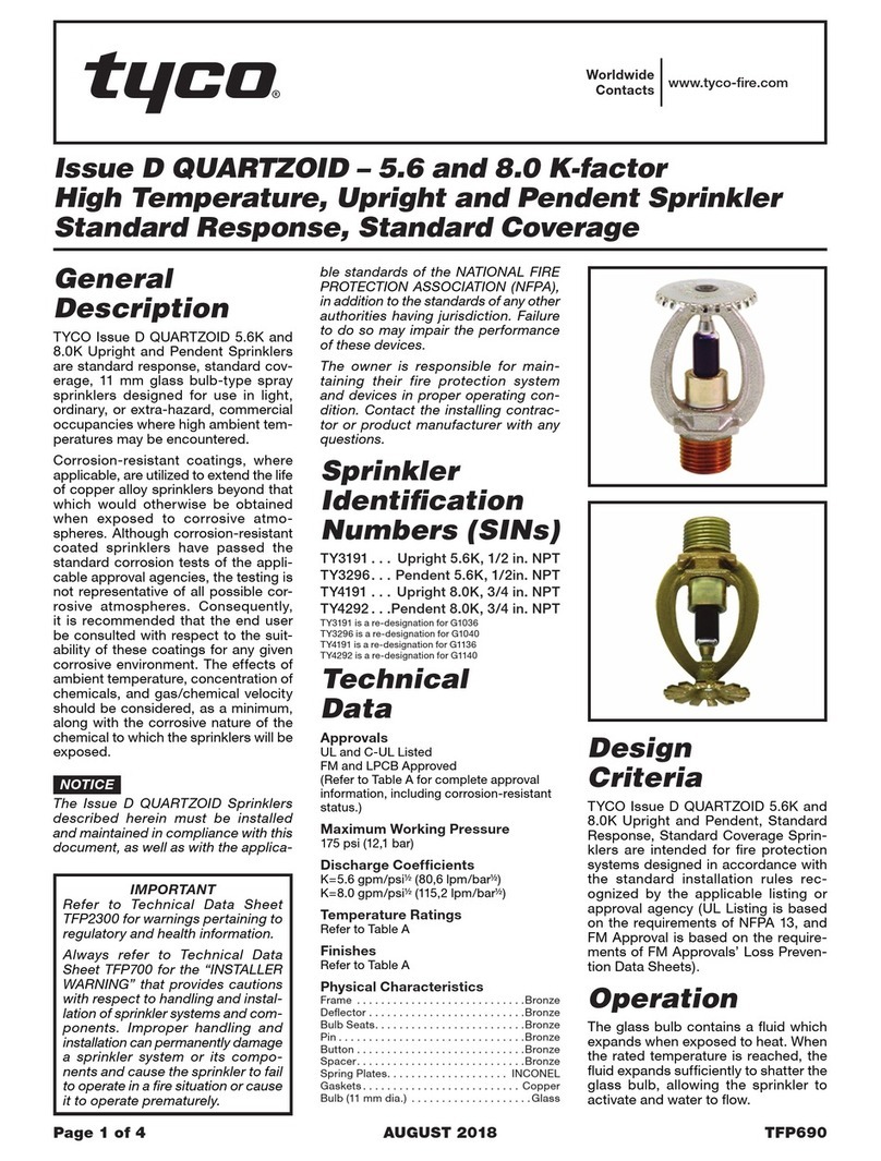
Tyco Issue D QUARTZOID User manual

Tyco

Tyco Issue D QUARTZOID User manual

Tyco B-1 User manual

Tyco

Tyco B-1 User manual

Tyco DV-5A User manual

Tyco

Tyco DV-5A User manual

Tyco PROTECTOSPRAY EA-1 User manual

Tyco

Tyco PROTECTOSPRAY EA-1 User manual

Tyco EC-5 Series User manual

Tyco

Tyco EC-5 Series User manual

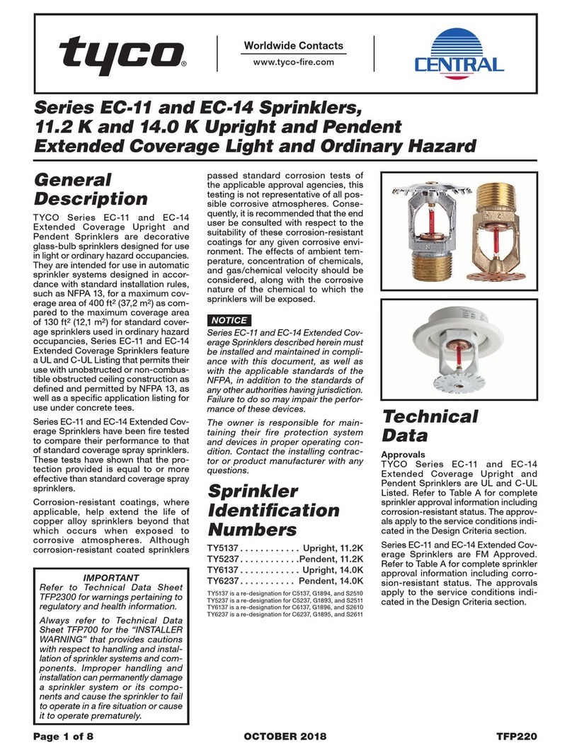
Tyco EC-11 Series User manual

Tyco

Tyco EC-11 Series User manual

Tyco Issue A User manual

Tyco

Tyco Issue A User manual

Tyco TY-FRB Series User manual

Tyco

Tyco TY-FRB Series User manual

Tyco K17-231 User manual

Tyco

Tyco K17-231 User manual
Tyco AQUAMIST AM4 User manual

Tyco

Tyco AQUAMIST AM4 User manual

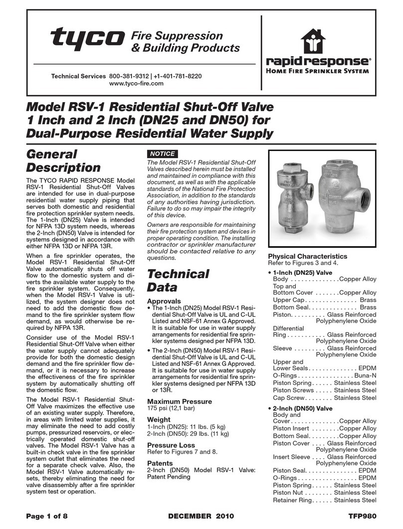
Tyco RAPID RESPONSE RSV-1 User manual

Tyco

Tyco RAPID RESPONSE RSV-1 User manual

Tyco D3 PROTECTOSPRAY User manual

Tyco

Tyco D3 PROTECTOSPRAY User manual
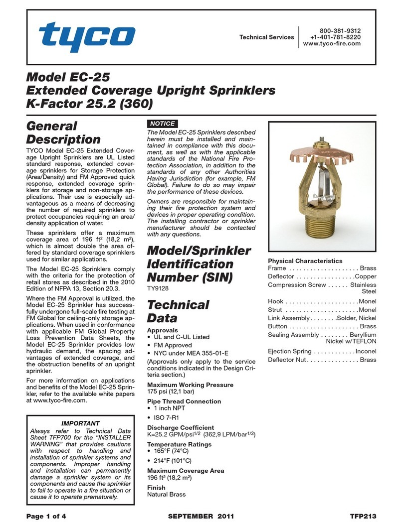
Tyco EC-25 User manual

Tyco

Tyco EC-25 User manual

Tyco EC-25 User manual

Tyco

Tyco EC-25 User manual

Tyco FSC 80 K-factor Flush Sprinkler User manual

Tyco

Tyco FSC 80 K-factor Flush Sprinkler User manual

Tyco LFII Series User manual

Tyco

Tyco LFII Series User manual

Popular Firefighting Equipment manuals by other brands

Ampac Sav-Wire 2 Base installation guide

Ampac

Ampac Sav-Wire 2 Base installation guide

Task Force Tips Master Foam Series Instructions for installation, operation and maintenance

Task Force Tips

Task Force Tips Master Foam Series Instructions for installation, operation and maintenance

Task Force Tips FX100-NN manual

Task Force Tips

Task Force Tips FX100-NN manual

Vimpex BIG HP18-H200-B1 Operation manual

Vimpex

Vimpex BIG HP18-H200-B1 Operation manual

Intelagard MERLIN Operator's manual

Intelagard

Intelagard MERLIN Operator's manual

Idex AWG ALCO POWER FIGHTER instruction manual

Idex

Idex AWG ALCO POWER FIGHTER instruction manual

Akron Brass 3406 quick start guide

Akron Brass

Akron Brass 3406 quick start guide

3M SCOTT EZ-SCAPE PRO Operating & maintenance instructions

3M

3M SCOTT EZ-SCAPE PRO Operating & maintenance instructions

Plumis Automist Smartscan Handbook

Plumis

Plumis Automist Smartscan Handbook

Waterous Advantus Foam Manager Operation and maintenance manual

Waterous

Waterous Advantus Foam Manager Operation and maintenance manual

TFT Working Fire Instructions for installation, safe operation and maintenance

TFT

TFT Working Fire Instructions for installation, safe operation and maintenance

manuals.online logo
manuals.online logoBrands
  • About & Mission
  • Contact us
  • Privacy Policy
  • Terms and Conditions

Copyright 2025 Manuals.Online. All Rights Reserved.