Fike Epaco RC80 Owner's manual

Manual P/N E06-054
Rev. No: 1, 07/04
E10-0069
Installation and Operation
Instructions


FIKE CORPORATION
FM 3020541 Fike Explosion Protection System Page i
P/N E06-054 Rev. 1 07/04
Introduction
Fike is pleased to present a new Installation,
Operation and Maintenance Manual for our
Explosion Protection System. This document
has been created to incorporate the most up-to-
date information available for this Fike product
and to make it easy to use.
Who should read this manual?
This manual is intended for those individuals
who are custodians of the Fike EPACO
System. Others such as architects, engineers,
sales and marketing personnel, etc. will find the
information useful as well.
Warranty Information
Fike provides a one-year limited manufacturer’s
warranty on the product identified in this manual.
Copies of the warranty can be obtained from an
authorized Fike sales outlet. An authorized Fike
sales outlet, using the MRA procedure, must
return warranty items. See Section 11 of this
manual for details of returning product to Fike.
Limitation of Liability
Fike Corporation cannot be held liable for any
damages resulting from the use or misuse of this
product.
Copyright, Trademark and Licensing
Notice
All Fike documentation and hardware are
copyright with all rights reserved. No part of this
product may be copied, reproduced or
transmitted by any mechanical, photographic,
electronic or other method without Fike’s prior
written consent. Fike product names are
trademarked; other product names, as
applicable, are trademarks of their respective
holders.
Disclaimer
The information contained in this manual is as
accurate as possible. This manual is intended
to be an aid to Fike authorized sales outlets or
engineers charged with the installation and
maintenance of the Fike Explosion Protection
System. Fike does not warrant that this manual
is technically correct, complete or the product
referenced herein is free from minor flaws. Fike
reserves the right to change the information
contained in this manual without notice.
Quality Notice
Fike Corporation has maintained ISO 9001
certification since 1996. Prior to shipment, we
thoroughly test our products and review our
documentation to assure the highest quality in
all respects. In a spirit of continuous
improvement, Fike welcomes your suggestions.
Please direct all suggestions or comments to
Fike Blue Springs Product Support
Phone: +1-816-229-3405
Fax: +1-816-229-0314
or
Fike Europe Product Support
Phone: +32-14-21-00-31
Fax: +32-14-21-07-43
Any suggestions or comments become the
property of Fike Corporation.

FIKE CORPORATION
Page ii Fike Explosion Protection System FM 3020541
07/04 P/N E06-054 Rev. 1
This page intentionally left blank.

FIKE CORPORATION
FM 3020541 Fike Explosion Protection System Page iii
P/N E06-054 Rev. 1 07/04
Table of Contents
1.0 Terms and Symbols Used In This Manual............................................................................................1
2.0 EPACO System Overview.......................................................................................................................2
3.0 System Components...............................................................................................................................3
4.0 Installation ...............................................................................................................................................4
4.1 Installation Overview .............................................................................................................................4
4.2 Power Specifications .............................................................................................................................4
4.3 Relay Card (RC8) ..................................................................................................................................5
4.4 Circuit Connections ...............................................................................................................................6
4.4.1 24VDC Power (P4)........................................................................................................................ 6
4.4.2 Relay (P2 & P3)............................................................................................................................. 6
4.4.3 Status Bus (P1) ............................................................................................................................. 7
5.0 Operation .................................................................................................................................................8
5.1 Configuration .........................................................................................................................................8
5.1.1 Dip Switch Configuration ............................................................................................................... 8
5.1.2 PC Configurations ......................................................................................................................... 8
5.2 RC8 Status ............................................................................................................................................9
5.2.1 RC8 Normal State ......................................................................................................................... 9
5.2.2 RC8 Trouble or Alarm State .......................................................................................................... 9
5.3 Relay Events .......................................................................................................................................10
6.0 Periodic Maintenance ...........................................................................................................................14
6.1 General................................................................................................................................................14
6.2 Inspection Procedure...........................................................................................................................14
6.3 Routine Inspections.............................................................................................................................14
6.4 Three-Year Replacement ....................................................................................................................14
6.5 Ten-Year Replacement .......................................................................................................................14
7.0 Decommissioning Procedure / Check-List.........................................................................................15
8.0 RC8 Spare Parts....................................................................................................................................16
9.0 LED Diagnostics....................................................................................................................................16
10.0 Specifications........................................................................................................................................17
11.0 Repair and Return Authorization.........................................................................................................18

FIKE CORPORATION
Page iv Fike Explosion Protection System FM 3020541
07/04 P/N E06-054 Rev. 1
List of Exhibits
Exhibit 2-1 EPACO System Block Diagram ....................................................................................................... 2
Exhibit 3-1 RC8 Photo ........................................................................................................................................ 3
Exhibit 4-1 RC8 Block Diagram .......................................................................................................................... 5
Exhibit 4-2 RC8 Bottom View – P3-P4 Wiring Connections............................................................................... 6
Exhibit 4-3 RC8 Power Input Wiring ................................................................................................................... 6
Exhibit 4-4 RC8 Relay Wiring ............................................................................................................................. 6
Exhibit 4-5 RC8 Top View – P1-P2 Wiring Connections .................................................................................... 6
Exhibit 4-6 Status Bus Wiring ............................................................................................................................. 7
Exhibit 5-1 Serial Port......................................................................................................................................... 8
Exhibit 5-2 DIP Switches .................................................................................................................................... 8
Exhibit 5-3 Power LED ....................................................................................................................................... 9
Exhibit 5-4 Status Bus LED ................................................................................................................................ 9
Exhibit 5-5 Trouble LED ..................................................................................................................................... 9
Exhibit 5-6 Relay Events Table ........................................................................................................................ 10
Exhibit 5-7 DIP Switch Configuration Table for RC8 ........................................................................................ 11
Exhibit 5-8 EPWorks™ Configurations 1 - 6 .................................................................................................... 12
Exhibit 5-9 EPWorks™ Configurations 7 - 12 .................................................................................................. 13
Exhibit 7-1 Decommissioning Steps ................................................................................................................. 15
Exhibit 8-1 Spare Parts List .............................................................................................................................. 16
Exhibit 9-1 LED Diagnostics ............................................................................................................................. 16
Annex A EPACO Wiring Diagram..................................................................................................................... 19

FIKE CORPORATION
FM 3020541 Fike Explosion Protection System Page 1 of 20
P/N E06-054 Rev. 1 07/04
1.0 TERMS AND SYMBOLS USED IN THIS MANUAL
Term/Symbol Description
Fuse symbol. This designation represents a circuit protection fuse. The
fuse is rated at the amperage noted next to this marking.
DB9
Computer Connection symbol. This designation represents the location
for the computer connection. Using a straight-through serial cable, the RC8
can be connected from this DB9 connection to a computer serial port. The
EP Works software can be installed on the computer and provide
operational information.
Status Bus symbol. The Status Bus circuit is a low speed network
connection that sends and receives status information to Annunciator
Module.
DC Power symbol. This symbol is located on the RC8 P3 terminal. It
designates the 24VDC input terminals and the 24VDC output terminals to
the next RC8 in the system.
NCNO C
Relay symbol. This symbol located on the top and bottom of the RC8 P2
and P3 terminal outputs. It designates the relay output wiring connections.

FIKE CORPORATION
Page 2 of 20 Fike Explosion Protection System FM 3020541
07/04 P/N E06-054 Rev. 1
2.0 EPACO SYSTEM OVERVIEW
The EPACOSystem is a modular detection
and control system combining the latest in
addressable technology with simplicity of
installation and maintenance. All system
modules are DIN rail mounted to allow for a
variety of installation options. Three (3) bus type
communication circuits tie the various system
modules into one easy to operate protection
system. A non-volatile history buffer allows for
enhanced diagnostic ability to troubleshoot
process situations. With the optional
Annunciator Module (AM), the customer has the
ability to step through a menu format to retrieve
process history without having to wait for a
service agency to arrive on site.
This manual will provide the necessary
information to properly install and monitor the
Relay Card (RC8) for the EPACOSystem.
The commissioning and service should be
performed by certified service engineers and
outlets specifically trained on this system.
Exhibit 2-1 EPACO System Block Diagram
POWER
SUPPLY
UNIT
ANNUNCIATOR
MODULE EXPLOSION
PROTECTION
CONTROLLER
RELAY
CONTROL 8
(8 RELAYS)
UP TO 6
RELEASING
DEVICES

FIKE CORPORATION
FM 3020541 Fike Explosion Protection System Page 3 of 20
P/N E06-054 Rev. 1 07/04
3.0 SYSTEM COMPONENTS
The cornerstone of the system is the Explosion
Protection Controller (EPC). Three colored LEDs
provide instant visual indication of system
status. The DIN rail mounting allows for
flexibility when choosing an enclosure. The EPC
is an addressable panel that has the ability to
retain an event history for enhanced system
diagnostics. The EPC is a component that
allows mounting in close proximity to the
protected environment, thereby minimizing field
wiring. Shorter wire runs greatly reduce the
interference from electrical and radio frequency
sources, allowing for a much more reliable
protection system. The EPC’s detection inputs
can be programmed for pressure warning,
threshold detection, and rate of rise detection. It
also has a contact closure detection circuit to
support thermal, infrared, or other switch-closure
type detection devices1. A supervisory input
circuit is provided to monitor suppression
container pressure or other similar system status
safeguards. The EPC has a remote disable
input contact to allow for disabling the EPC from
a customer PLC or other remote device during
product loading, cleaning, or maintenance. DIP
switches allow for basic system programming.
An RS232 connection is available at each
module for connection to a PC. Using the EP
WorksTM software, an authorized user can
access system diagnostics and more complex
programming by PC.
The EPC is powered by the other key
component in the EPACOsystem, the Power
Supply Unit (PSU). The PSU has six separate
24 VDC, 1 amp power output circuits capable of
powering up to four EPCs in addition to other
components of the EPACOsystem. The PSU
has the flexibility of containing its own battery
backup supply or the customer has the option of
supplying a backup power source. The PSU
has an imbedded power shutdown procedure in
the event of AC power failure, which prevents
the backup batteries from being completely
depleted. In addition to powering EPCs, the PSU
can power an Annunciator Module (AM) and
Relay Card Modules (RC8). The power circuit
dedicated for the Annunciator Module can not be
shut off. All other power output circuits can be
shut off for service on the various system
components. The PSU may be eliminated if
1FM Approved switch closure for use with Fike threshold
detector (E61-042-x) and Rate of Rise detector (E61-056-x).
Other switch closure, thermal, or infrared devices are not
approved by FM.
battery backed, uninterrupted 24VDC, 0.500
Amps power per module can be provided by
others. For an FM approved installation without
the PSU, the uninterruptible power must be U.L.
1778 “Uninterruptible Power Systems” listed,
and conform to NFPA 72 “National Fire Alarm
Code”, NFPA 70 “National Electrical Code”
(Articles 700 and 701), NFPA 110 “Standard for
Emergency and Standby Power Systems”, and
NFPA 111 “Standard on Stored Electrical
Energy Emergency and Standby Power
Systems”.
The Annunciator Module (AM) provides a central
communication point for diagnostics. This
module will typically be installed in an area
removed from the process environment such as
a control room. The AM has two push buttons to
access the various menus and three numbered
LEDs for identification of the system statuses
within the menus.
The Relay Card Module (RC8) provides the user
with a block of eight Form “C” relays for
equipment shutdowns and remote notification of
system trouble and alarm conditions. On-board
LEDs display status for instant visual verification
of each relay. DIP switches are provided for
configuring the relay’s operation.
Exhibit 3-1 RC8 Photo

FIKE CORPORATION
Page 4 of 20 Fike Explosion Protection System FM 3020541
07/04 P/N E06-054 Rev. 1
4.0 INSTALLATION
4.1 INSTALLATION OVERVIEW
The effectiveness of active explosion protection
systems, such as explosion suppression and
explosion isolation, depends upon the
instantaneous reaction of the protection system
and is a direct function of its speed of response.
It is therefore, critical that all possible measures
are taken to reduce the individual system
components’ response times to an absolute
minimum.
An active explosion protection system basically
consists of three components: One or more
explosion detectors, an electronic system
controller, and one or more protective devices
such as explosion suppressors or isolation
valves. Instrumentation wiring interconnects
these components.
The system controller is microprocessor-based
and shall be installed in a location that maintains
the EPC’s temperature rating of -18°C to 43°C
(0°F to 110°F) when it is installed in an auxiliary
housing. For FM Approved installations the
housing shall be a lockable enclosure
conforming to the installed area requirements as
defined by NEMA 250 “Enclosures for Electrical
Equipment (1000 Volts Maximum).”
Besides its function as a fire controller it also
incorporates an event table and a self-checking
feature to continuously monitor the complete
system-loop for errors or system defects.
Electronic devices, microprocessors,
pyrotechnic initiators, and field wiring are
influenced by the electromagnetic “environment”
surrounding these components. The use of
cellular telephones, transmitters, induction
motors, welding equipment or the presence of
power cables and transformers can create
environments with high levels of electromagnetic
radiation, resulting in induced electrical “noise”
or voltage peaks.
Such effects are known to designers and
manufacturers of instrumentation and control
systems (PLC’s), used in industrial
environments and are handled through the use
of specially designed electronic filters. These
filters neutralize the unwanted noise and offer a
“clean” signal for further processing. The filters,
however, result in a delay in the processing of
signals, and can therefore only be applied with
great care in explosion protection systems
where the effectiveness depends on the overall
response time.
In active explosion protection systems, a
balance must be maintained: The system must
be extremely fast to achieve the required
effectiveness, but at the same time must be
stable and insensitive to surrounding sources of
noise.
The system controller will detect and report
major system troubles (such as ground faults,
wire disconnection, and unstable input or output
signals) and indicates the need for appropriate
action.
The system controller will also detect
unacceptable levels of electromagnetically
induced noise. If the magnitude of the noise is
such that this may result in a risk for
spontaneous system activation or affect the
system’s performance, the controller will revert
to its default error-mode.
It is essential to practice extreme caution when
selecting component location, cable
specifications, cable routes, and the
“cleanliness” of the offered power source. In
order to reduce the electromagnetic induced
noise to a level that will not affect the required
performance of the explosion protection system,
verify all earth connections. It is preferred to
have the enclosure and conduits connected to
Protective Earth (similar with other building
grounds) while the drain wires from the field
wiring and each module ground connected to a
separate Instrument Earth. This Instrument
Earth connection shall not have inductive or
capacitive loading such as motors, welders, or
other industrial equipment. Where a separate
earth connection is not available, the drain wires
and module ground connections should be
made to battery common. Complying with the
following recommendations will help minimize
the induced noise to acceptable levels.
4.2 POWER SPECIFICATIONS
The AC supply (commonly supplied to the
EPACO Power Supply Unit, PSU) shall be wired
through a dedicated circuit to a
1002/120/240VAC 15 or 16 Amp circuit breaker.
High voltage circuits may NOT be run in the
same conduit as low voltage circuits.
Cabling from transformer to PSU shall be
1.3 mm2(16AWG) minimum not to exceed
3 meters (10 feet).
2Not FM Approved for 100 VAC.

FIKE CORPORATION
FM 3020541 Fike Explosion Protection System Page 5 of 20
P/N E06-054 Rev. 1 07/04
Cabling from PSU to RC8 shall be 0.8 mm2
(18AWG) minimum not to exceed 10 Ω
resistance.
A keyed selector switch is recommended in the
PSU to RC8 power supply cabling to facilitate
reset of the RC8. This shall have a 30V, 1A
rating.
4.3 RELAY CARD (RC8)
The Relay Card (RC8) is a DIN rail mounted,
fully programmable module containing eight (8)
Form “C” relays. Each relay is equipped with a
green LED to provide a visual indication of the
relay state. These relays facilitate process
shutdowns or other actions in response to
conditions recognized by the EPACOsystem.
The RC8 is powered with 24VDC from the PSU.
Up to four (4) RC8s can be connected in parallel
to the power supply. The RC8 is capable of
communicating on the Status Bus for
exchanging status information and remote
control of the outputs. A history of the relay
states is captured in the Annunciator Module.
Exhibit 4-1 RC8 Block Diagram
OUTPUTS
POWER-24 VDC (18-30 VDC)
2 WIRE, TWISTED SHIELDED CABLE
INPUTS RC 8 MODULE
E10-0069
PSU, AM, EPC(S)
BELDEN 9841 OR EQUIVALENT
NETWORKS
P3-4
P3-3
P3-2
P3-1
P2-4
P2-3
P2-2
P4
P1
P2-1 CONTACT TERMINAL 1
CONTACT TERMINAL 2
CONTACT TERMINAL 3
CONTACT TERMINAL 4
CONTACT TERMINAL 5
CONTACT TERMINAL 6
CONTACT TERMINAL 7
CONTACT TERMINAL 8
STATUS BUS RC8(S) - STATUS BUS,
FIKE CORPORATION
Page 6 of 20 Fike Explosion Protection System FM 3020541
07/04 P/N E06-054 Rev. 1
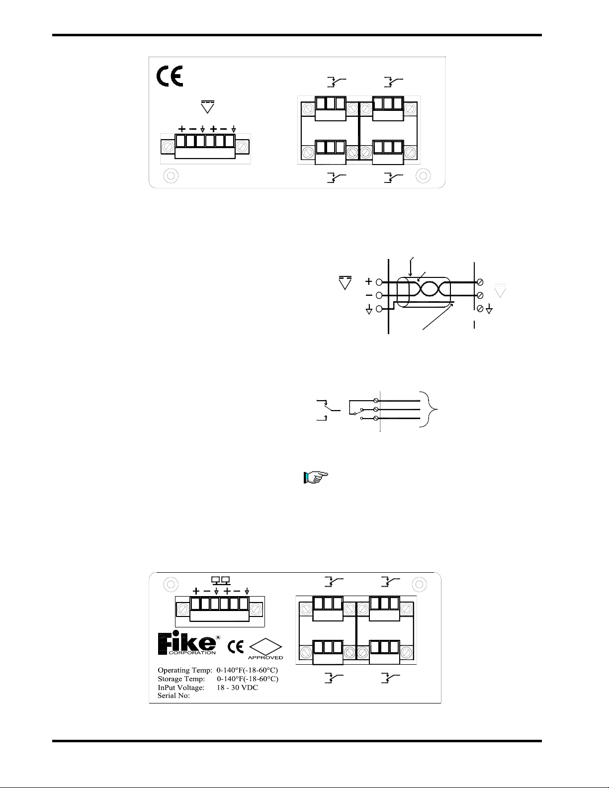
Exhibit 4-2 RC8 Bottom View – P3-P4 Wiring Connections
4.4 CIRCUIT CONNECTIONS
4.4.1 24VDC Power (P4)
Power Input requires between 18 to 30 Vdc, at
500mA. For the Relay Card, power needs to be
from the EPACO PSU or an approved power
source for proper operation of the status bus.
4.4.2 Relay (P2 & P3)
Relays 1 through 8 are available to provide
EPACO system status to monitoring equipment.
The relays are a “fail-safe” relay that will transfer
upon any system upon the programmed
condition. This can be used for equipment
shutdown, visual, audible, or other type
annunciation. Trouble conditions may or may
not affect the protection system’s ability to
respond to a deflagration, but must be
acknowledged and identified prior to continuing
to run the process.
Exhibit 4-3 RC8 Power Input Wiring
Exhibit 4-4 RC8 Relay Wiring
Note: The relay designations (NO, NC, and
C) are shown in the de-energized state
with no power applied. When the RC8 is
powered and the system is in the NORMAL
state, the relay is energized. (The relay
marking is opposite of what is expected).
Exhibit 4-5 RC8 Top View – P1-P2 Wiring Connections
CNCNO
6
P3
CNCNO
8
E10-0069
NCNO
5
24VDC
NC
7
NO
P4
C
C
Process Monitoring
NO
C
NC
Equipment (*See Note*)
24VDC
-
+
Shield
Twisted Pair
No
Connection
P2
24VDC
of Drain Wir
e
No termination
[
insulate
]
EPC, AM or RC8
PSU
Contact: www.fike.com
FM
CNCNO
P2
NC CNO
4
2
NCNO
P1
NC
3
NO
A B 1
C
C

FIKE CORPORATION
FM 3020541 Fike Explosion Protection System Page 7 of 20
P/N E06-054 Rev. 1 07/04
4.4.3 Status Bus (P1)
The Status Bus is a low speed communication
bus that transmits control information between
the EPC, Power Supply, Annunciator Module
and Relay Modules. Belden 9841 or RE-Y2Y
cabling is recommended for this circuit.
Maximum resistance R=50 Ω, inductance
L=100uH, and capacitance C=0.02uF with a
maximum length of 300m (1,000 ft).
Note: The B+ connects to the A+ on the next
device; similarly the B– connects to the A– of
the next device. Install the 140 Ω, 1/2 watt
resistor at each end as shown.
Note: The drain wire should only be con-
nected on one end of each wire run. Make
sure that the drain wire, which is not
connected to a terminal, is cut and insulated
from making contact to metal or other wiring
connections.
Exhibit 4-6 Status Bus Wiring
Additional RC8
Twisted Pair
Shield Wire
-
+-+
Relay Module
BA
(RC8) #1
P1 Shield -
+-+
BA
RC8 #2
P1 -
+-+
Last RC8(Up to 4)
BA
P1
of Drain Wire [ insulate ]
-
+-+
-
++
-
Twisted Pair
Shield Wire
Controller (EPC) #1
Explosion Protection
-++
-
BA
P1 Shield
Annunciator
Module (AM)
BA
++
--
BA
P1
EPC #2 Last EPC (Up to 4)
B
-+-
P1
A
+
Additional EPC
Unit (PSU)
Power Supply
BA
No termination
Shield Wire
Twisted Pair
P2 Shield P1
140 ohm
140 ohm

FIKE CORPORATION
Page 8 of 20 Fike Explosion Protection System FM 3020541
07/04 P/N E06-054 Rev. 1
ADD
12
MODE
1234
5.0 OPERATION
5.1 CONFIGURATION
The RC8 is a fully programmable module.
System configuration can be performed with
DIPswitches on these modules or by way of a
DB9 serial port connection to a PC using
EPWorks™ Software. RC8 addressing is done
using the two ADD (address) DIPswitches. The
four MODE DIP switches are used for
programming specific relay configurations.
Expanded programming may be created via PC
with Fike's EPWorks™ Software.
Exhibit 5-1 Serial Port
5.1.1 Dip Switch Configuration
The EPACO system can have multiple RC8’s
connected to a single system. The ADD
switches enable the system to distinguish
between multiple RC8’s. The RC8 is configured
to one of six (6) configurations using the MODE
DIP switches on the face of the unit. The
configuration of the DIP switches set the relay
operation parameters of the RC8. The DIP
switches incorporate a safety feature that
prevents a programming change should one of
the DIP switches inadvertently get changed.
5.1.2 PC Configurations
There are twelve (12) relay configurations that
can be selected using a PC with EPWorks™
software. These relay configurations are more
elaborate than are available with the DIP switch
configurations.
NOTE: Address and configuration changes
are to be made by Fike authorized
engineers or technicians only.
Exhibit 5-2 DIP Switches
DB9
2A
- 2A -
21
65
MODEADD
4
3
DB9
24VDC
8
7

FIKE CORPORATION
FM 3020541 Fike Explosion Protection System Page 9 of 20
P/N E06-054 Rev. 1 07/04
24VDC
Green
Green
1
Green
5.2 RC8 STATUS
The RC8 is a process interface for the EPACO
system. The following tasks are accomplished
by the RC8:
•Communicates system status via relays for
user interface
•Direct shut downs, slow downs, and remote
notifications of system trouble and alarm
conditions
•Remote location of interface, separate from
the hazard zone
The RC8 operation can be classified into two main states of operation: Normal and Trouble / Alarm. Each
of these states is described in sections 5.2.1 and 5.2.2. Exhibit 5-6 further describes other conditions within
these states in a handy spreadsheet for quick reference.
5.2.1 RC8 Normal State
When power is applied to the RC8, it performs a 15 second
initialization. At the end of the initialization, the Status Bus LED will
turn on and the appropriate relays and relay LEDs will be energized to
indicate the current status of the EPACO system.
5.2.2 RC8 Trouble or Alarm State
A trouble or alarm occurs on the EPACO system if any one of the
supervised circuits experiences a wiring fault open or short condition, if
a configuration is invalid, if the system is disabled, if a process
pressure warning level is exceeded, if the input voltage drops below
18VDC or the activation criteria on the detector inputs have been met.
In the Trouble or Alarm State the green LED programmed to respond
to the fault or alarm condition will turn off, and the corresponding relay
is de-energized. Depending on the cause of the trouble, the system
may or may NOT be completely functional. Each trouble should be
investigated to determine the cause and promptly fixed. Each trouble,
except for remote disable, will latch at the EPC. If the trouble is
resolved, the EPC trouble can be cleared by disabling and re-enabling
via the remote disable input, by cycling of the power input to the EPC,
or by disabling and re-enabling the EPC via the Annunciator Module
(see Annunciator Module Installation and Operation Instructions E06-
053). If the remote disable is active, the EPC will enter the trouble
state. When the remote disable is returned to normal, the EPC will
automatically clear to the normal state, if no other troubles are present,
without cycling the power.
Note: The alarm state will activate the system. If the system is
reset after an alarm, it is typical to have an open wiring fault on
the Series Firing circuit, since the actuator(s) have activated.
Exhibit 5-3 Power LED
Exhibit 5-4 Status Bus LED
Exhibit 5-5 Trouble LED

FIKE CORPORATION
Page 10 of 20 Fike Explosion Protection System FM 3020541
07/04 P/N E06-054 Rev. 1
5.3 RELAY EVENTS
The RC8 relays can be configured for 55 different EPACO system events as shown in the table below. The
relay functionality can be selected through one of the six DIP switch configurations listed below in Exhibit 5-
7 or one of the twelve EPWorksconfigurations shown in Exhibit 5-8 or 5-9.
Module Description Module Description
EPC x No EPC or EPC Shutdown PSU No PSU/External Power Supply used
or No Communications
EPC x Normal Operation Mode PSU Normal Operation Mode
EPC x Trouble on one of the Input Circuits PSU Fan Trouble
EPC x Pressure Warning Level Exceeded PSU Ground Fault Trouble
EPC x Trouble on one of the Output Circuits PSU Battery or Charge Trouble
EPC x Trouble on the Fire Bus PSU AC Trouble
EPC x PreDischarge Condition Satisfied PSU Battery Backup being Utilized
EPC x Supervisory Input Active PSU Output Trouble
EPC x EPC has Activated Releasing Outputs PSU Outputs Disabled
EPC x EPC has been Disabled PSU Auto Shutdown Mode
EPC x Failure during Arming System Status Bus Communication Failure
“x” = EPC 1 through 4
Exhibit 5-6 Relay Events Table

FIKE CORPORATION
FM 3020541 Fike Explosion Protection System Page 11 of 20
P/N E06-054 Rev. 1 07/04
Exhibit 5-7 DIP Switch Configuration Table for RC8
8
EPC 4
Alarm
EPC 1
Arming Trouble
EPC 2
Arming Trouble
EPC 3
Arming Trouble
EPC 4
Alarm
RC8
Bus Failure
N/A
7
EPC 4
Trouble
EPC 1
Supervisory
EPC 2
Supervisory
EPC 3
Supervisory
EPC 4
Trouble
N/A
N/A
6
EPC 3
Alarm
EPC 1
PreDischarge
EPC 2
PreDischarge
EPC 3
Alarm
EPC 4
PreDischarge
PSU
Output Failure
N/A
5
EPC 3
Trouble
EPC 1
Shutdown
EPC 2
Shutdown
EPC 3
Trouble
EPC 4
Shutdown
PSU
Fan Failure
N/A
4
EPC 2
Alarm
EPC 1
Disable
EPC 2
Alarm
EPC 3
Disable
EPC 4
Disable
Ground
Fault
N/A
3
EPC 2
Trouble
EPC 1
Pres. Warning
EPC 2
Trouble
EPC 3
Pres. Warning
EPC 4
Pres. Warning
Batt. Power
Failure
N/A
2
EPC 1
Alarm
EPC 1
Alarm
EPC 2
Disable
EPC 3
PreDischarge
EPC 4
Arming Trouble
AC Power
Failure
N/A
Relay Number
1
---- User Selectable with Software ----
EPC 1
Trouble
EPC 1
Trouble
EPC 2
Pres. Warning
EPC 3
Shutdown
EPC 4
Supervisory
PSU
Trouble
N/A
4
Off
Off
Off
Off
Off
Off
Off
On
Configure Clear - Used to change the configuration settings in the Relay Card.
PC Configure - Used to provide expanded programming options.
3
Off
Off
Off
Off
On
On
On
On
2
Off
Off
On
On
Off
Off
On
On
Mode Switch Position
1
Off
On
Off
On
Off
On
Off
On
Config Clear
PC Config
Config #
PC Config
1
2
3
4
5
6
Config Clear
EPC Trouble = No EPC or EPC Shutdown, Trouble on Input Circuit, Pressure Warning, Trouble on Output Circuit, Trouble on Fire Bus, PreDischarge, Supervisory
Input Active, EPC Disabled, or Failure During Arming.
EPC Alarm = Releasing Outputs Activated, or No EPC or EPC Shutdown.
Definitions

FIKE CORPORATION
Page 12 of 20 Fike Explosion Protection System FM 3020541
07/04 P/N E06-054 Rev. 1
Configuration 6
EPC 4 - Shutdown
EPC 4 - Input Trouble
EPC 4 - Pressure Warning
EPC 4 - Output Trouble
EPC 4 - Fire Bus Trouble
EPC 4 - PreDischarge
EPC 4 - Supervisory
EPC 4 - Disabled
EPC 4 - Activation
EPC 4 - Pressure Warning
EPC 4 - Disabled
EPC 4 - Shutdown
EPC 4 - Pressure Warning
EPC 4 - PreDischarge
EPC 4 - Supervisory
RC8 - Status Bus Failure
Configuration 5
EPC 3 - Shutdown
EPC 3 - Input Trouble
EPC 3 - Pressure Warning
EPC 3 - Output Trouble
EPC 3 - Fire Bus Trouble
EPC 3 - PreDischarge
EPC 3 - Supervisory
EPC 3 - Disabled
EPC 3 - Activation
EPC 3 - Pressure Warning
EPC 3 - Disabled
EPC 3 - Shutdown
EPC 3 - Pressure Warning
EPC 3 - PreDischarge
EPC 3 - Supervisory
RC8 - Status Bus Failure
Configuration 4
EPC 2 - Shutdown
EPC 2 - Input Trouble
EPC 2 - Pressure Warning
EPC 2 - Output Trouble
EPC 2 - Fire Bus Trouble
EPC 2 - PreDischarge
EPC 2 - Supervisory
EPC 2 - Disabled
EPC 2 - Activation
EPC 2 - Pressure Warning
EPC 2 - Disabled
EPC 2 - Shutdown
EPC 2 - Pressure Warning
EPC 2 - PreDischarge
EPC 2 - Supervisory
RC8 - Status Bus Failure
Configuration 3
EPC 1 - Shutdown
EPC 1 - Input Trouble
EPC 1 - Pressure Warning
EPC 1 - Output Trouble
EPC 1 - Fire Bus Trouble
EPC 1 - PreDischarge
EPC 1 - Supervisory
EPC 1 - Disabled
EPC 1 - Activation
EPC 1 - Pressure Warning
EPC 1 - Disabled
EPC 1 - Shutdown
EPC 1 - Pressure Warning
EPC 1 - PreDischarge
EPC 1 - Supervisory
RC8 - Status Bus Failure
Configuration 2
EPC 3 - Pressure Warning
EPC 3 - PreDischarge
EPC 3 - Supervisory
EPC 3 - Arming Trouble
EPC 3 - Shutdown
EPC 3 - Input Trouble
EPC 3 - Output Trouble
EPC 3 - Fire Bus Trouble
EPC 3 - Disabled
EPC 3 - Activation
EPC 3 - Shutdown
EPC 3 - Disabled
EPC 4 - Pressure Warning
EPC 4 - PreDischarge
EPC 4 - Supervisory
EPC 4 - Arming Trouble
EPC 4 - Shutdown
EPC 4 - Input Trouble
EPC 4 - Output Trouble
EPC 4 - Fire Bus Trouble
EPC 4 - Disabled
EPC 4 - Activation
EPC 4 - Shutdown
EPC 4 - Disabled
PSU - Battery Trouble
PSU - AC Trouble
Configuration 1
EPC 1 – Pressure Warning
EPC 1 - PreDischarge
EPC 1 - Supervisory
EPC 1 - Arming Trouble
EPC 1 - Shutdown
EPC 1 - Input Trouble
EPC 1 - Output Trouble
EPC 1 - Fire Bus Trouble
EPC 1 - Disabled
EPC 1 - Activation
EPC 1 - Shutdown
EPC 1 - Disabled
EPC 2 - Pressure Warning
EPC 2 - PreDischarge
EPC 2 - Supervisory
EPC 2 - Arming Trouble
EPC 2 - Shutdown
EPC 2 - Input Trouble
EPC 2 - Output Trouble
EPC 2 - Fire Bus Trouble
EPC 2 - Disabled
EPC 2 - Activation
EPC 2 - Shutdown
EPC 2 - Disabled
PSU - Fan Trouble
PSU - Ground Fault Trouble
PSU - Batt./Charge Trouble
PSU - AC Trouble
PSU - Battery Backup
RC8 - Status Bus Failure
Relay 1
Relay 2
Relay 3
Relay 4
Relay 5
Relay 6
Relay 7
Relay 8
Exhibit 5-8 EPWorks™ Configurations 1 - 6

FIKE CORPORATION
FM 3020541 Fike Explosion Protection System Page 13 of 20
P/N E06-054 Rev. 1 07/04
Configuration 12
PSU - AC Trouble
PSU – Batt./Charge Trouble
PSU - Fan Trouble
PSU - Ground Fault Trouble
PSU - Battery Backup
PSU - Output Trouble
PSU - Output Disabled
PSU - Shutdown
Configuration 11
EPC 1 - Supervisory
EPC 2 - Supervisory
EPC 3 - Supervisory
EPC 4 - Supervisory
RC8 - Status Bus Failure
PSU - Fan Trouble
PSU - Ground Fault Trouble
PSU - Batt./Charge Trouble
PSU - AC Trouble
PSU - Battery Backup
EPC 1-4 - Shutdown
EPC 1-4 - Input Trouble
EPC 1-4 - Pressure Warning
EPC 1-4 - Output Trouble
EPC 1-4 - Fire Bus Trouble
EPC 1-4 - PreDischarge
EPC 1-4 - Supervisory
EPC 1-4 - Disabled
EPC 1-4 - Activation
Configuration 10
EPC 1 - Disabled
EPC 1 - Shutdown
EPC 2 - Disabled
EPC 2 - Shutdown
EPC 3 - Disabled
EPC 3 - Shutdown
EPC 4 - Disabled
EPC 4 - Shutdown
Configuration 9
EPC 1 - Supervisory
EPC 1 - Pressure Warning
EPC 1 - PreDischarge
EPC 2 - Supervisory
EPC 2 - Pressure Warning
EPC 2 - PreDischarge
EPC 3 - Supervisory
EPC 3 - Pressure Warning
EPC 3 - PreDischarge
EPC 4 - Supervisory
EPC 4 - Pressure Warning
EPC 4 - PreDischarge
Configuration 8
EPC 1 - Pressure Warning
EPC 1 - Disabled
EPC 2 - Pressure Warning
EPC 2 - Disabled
EPC 3 - Pressure Warning
EPC 3 - Disabled
EPC 4 - Pressure Warning
EPC 4 - Disabled
Configuration 7
EPC 1 - Supervisory
EPC 1 - Shutdown
EPC 1 - Input Trouble
EPC 1 - Output Trouble
EPC 1 - Fire Bus Trouble
EPC 1 - Disabled
EPC 2 - Supervisory
EPC 2 - Shutdown
EPC 2 - Input Trouble
EPC 2 - Output Trouble
EPC 2 - Fire Bus Trouble
EPC 2 - Disabled
EPC 3 - Supervisory
EPC 3 - Shutdown
EPC 3 - Input Trouble
EPC 3 - Output Trouble
EPC 3 - Fire Bus Trouble
EPC 3 - Disabled
EPC 4 - Supervisory
EPC 4 - Shutdown
EPC 4 - Input Trouble
EPC 4 - Output Trouble
EPC 4 - Fire Bus Trouble
EPC 4 - Disabled
Relay 1
Relay 2
Relay 3
Relay 4
Relay 5
Relay 6
Relay 7
Relay 8
Exhibit 5-9 EPWorks™ Configurations 7 - 12

FIKE CORPORATION
Page 14 of 20 Fike Explosion Protection System FM 3020541
07/04 P/N E06-054 Rev. 1
6.0 PERIODIC MAINTENANCE
CAUTION: If assistance is needed before performing any maintenance or service work on the Fike
Explosion Protection equipment and/or systems, contact Fike for instructions. See
section 11.0 Repair and Return Authorization for contact information.
6.1 GENERAL
Routine system inspections shall be conducted
in accordance with the requirements of the
appropriate local authority having jurisdiction
and National Fire Protection Association
Standard Number 69, Explosion Prevention
System, current edition.
The inspection schedule and procedure set forth
below are provided as a minimum requirement
for Fike Explosion Protection System
Controllers, which operate in moderate
environments. These control panel instructions
are to be implemented in conjunction with
complete system inspection instructions.
During initial system checkout or start-up, the
Fike Factory Field Personnel, due to process
operational characteristics and/or historical
inspection data on the specific process, may
determine that an additional inspection is
required. If this occurs, it will be in addition to
the following maintenance schedule.
It is extremely important to closely monitor the
operational characteristics of your system during
the first few days and weeks after the initial
start-up.
6.2 INSPECTION PROCEDURE
The following is the recommended procedure to
follow when conducting an inspection.
Step 1: Disable the Control Panel
Step 2: Shunt the GCA’s and install jumpers
Step 3: Re-Arm the Control Panel and Disable
Step 4: Calibrate the pressure detectors
Step 5: Cycle the Explosion Isolation Valves – if
present
Step 6: Checkout the panel
Step 7: Reconnect the GCA’s and log the
container pressures and serial numbers
Step 8: Re-arm the system
6.3 ROUTINE INSPECTIONS
These inspections are to be performed by Fike
Field Personnel or personnel trained and
certified by Fike.
To perform an inspection, it is important to first
obtain all pertinent data that relates to the
specific system being inspected. The required
information includes:
!System Engineered Drawings
Component Location Drawing No._________
Field Wiring Drawing No.____________
!Copy of Manuals, Specifications or
Documents Referenced on Fike System
Engineered Drawings
!Inspection Equipment
!Operating Specifications on Each Component
Being Inspected
6.4 THREE-YEAR REPLACEMENT
Replace all system batteries.
6.5 TEN-YEAR REPLACEMENT
Replace all GCA actuators, following all safe
handling practices and recommendations.
Note: The ten-year replacement is based
upon a 70°F to 80°F (20°C to 30°C)
actuator temperature. The replacement
frequency may be more frequent when
exposure to higher temperature or harsh
environments is experienced.
This manual suits for next models
1
Table of contents
Other Fike Relay manuals


