Reset Test
Trip
%
60
40
20
3
2
10 5
7
6
4
19
8
RD1
RD1
RD3
RD1
0,3...3A0,03...0,3A 3...30A
CODICE • CODE N° TENTATIVI /INTERVALLO TEMPO • NUMBER OF ATTEMPTS / TIME INTERVAL
RD1A - RD1D - RD3AF 3/60S
RD3AT 5/10S
RD3AU 1/10S
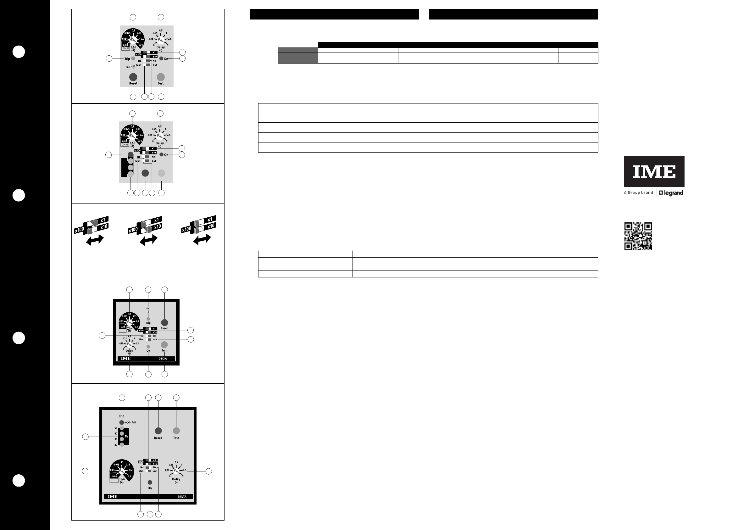
➊Predisposizione I
Δ
n soglia d’intervento 1
➋Selettore portata x1 / x10 / x100
1I mode o RD1E è dotato di un re è di prea arme con sog ia intervento fissa,
pari a 50% de va ore di I
Δ
n se ezionato .
Contro are che i va ore d’intervento se ezionato sia compatibi e con e sensibi-
ità minima ri evabi e da trasformatore toroida e abbinato.
➌• ➍LED segnalazione
LED spento
LED acceso
LED lampeggiante
➎Pulsante di prova
Permette di simu are a condizione di a arme, ’accensione de LED Trip e a
commutazione de re è d’uscita.
➏Pulsante di ripristino
➐Selettore ripristino
Man (manua e) = o stato di a arme permane fino a quando ’operatorenon agi-
sce su tasto RESET
Aut (automatico) = ad a arme intervenuto, ’apparecchio provvede automatica-
mente a ripristino, facendo a cuni tentativi.
Terminati i tentativi, se i dispositivo non si è ripristinato, ’apparecchio entra in
stato di a arme definitivo e deve essere ripristinato manua mente.
I ampeggio contemporaneo dei tre LED gialli, segna a ’esaurimento dei tentati
vi di ripristino.
I ripristino è inibito con corrente differenzia e persistente: ≅50% I
Δ
n impostata
➑Selettore stato relé uscita: Nd (norm. diseccitato) sicurezza negativa -
Ne (norm. eccitato) sicurezza positiva.
I re è di prea arme è sempre norm. diseccitato (mod. RD1E).
➒Predisposizione ritardo intervento
ATTENZIONE ! Se ezionando a sog ia d’intervento
ne a posizione 0,03 viene automaticamente esc uso i ritardo
intervento, indipendentemente da a posizione de se ettore di portata ➋.
Per predisporre sog ia di intervento I
Δ
n = 30mA con intervento istantaneo
se ezionare 0,03 e accertarsi che i se ettore ➋sia in posizione x1.
➓Indicazione istantanea della corrente differenziale (in % de va ore I
Δ
n impostato).
ISTRUZIONI DI CABLAGGIO
• La posizione di fissaggio risu ta comp etamente indifferente ai fini de funziona-
mento.
• Le operazioni di predisposizione (soglia intervento, tempo ritardo, ecc.) devono
essere effettuate con apparecchio non alimentato.
• Rispettare scrupo osamente o schema d'inserzione, una inesat tezza nei co egamenti è ine-
viitabi mente causa di funzionamento anoma o o di danni a 'apparecchio.
• L'ottenimento de a piena funziona ità de sistema di protezione differenzia e è egato a e mo-
da ità di insta azione, per cui si consig ia:
☞Ridurre a minimo a distanza tra toroide e re è
☞Uti izzare cavi schermati o intrecciati per a oro connessione
☞Evitare di disporre i cavetti di connessione toroide-re è para e amente a conduttori
di potenza
☞Evitare di insta are toroide e re è in prossimità di sorgenti di campi e ettromagneti
ci intensi (grossi trasformatori).
☞ So o i conduttori attivi attraversano i toroide (dis.D1)
☞ Uti izzando cavo schermato, ’armatura deve essere co egata a terra come da
(dis.D2)
☞ I conduttori devono essere posizionati a centro de toroide (dis.D3). ■
➊Setting intervention threshold I
Δ
n1
➋Range selector x1 / x10 / x100
1Mode RD1E has a pre-a arm re ay with fixed intervention thresho d equa to
50% of se ected I
Δ
n va ue .
Check that se ected intervention va ue matches the owest sensibi ity detecta -
b e by the connected ring current transformer.
➌• ➍Signaling LED
LED off
LED on
LED blinking
➎Test key
It a ows to simu ate a arm condition, LED Trip switching on and output re ay
switching.
➏Reset key
➐Automatic-manual reset switch
Man (manua ) = the a arm stays unti the operator doesn’t act on RESET key
Aut (automatic) = when a arm occurred, this unit automatica y resets, making
some attempts.
When attempts are over, if the device didn’t reset, the meter enters the definiti
ve a arm state and it has to be manua y reset.
The simu taneous b inking of the three yellow LED’s signa s that reset attempts
are over.
Reset is not possib e with persistent residua current: ≅50% I
Δ
n.
➑Switch for state of output relay: Nd (norma y de-energised) negative security
Ne (norma y energised) positive security.
Pre-a arm re ay is a ways norma y de-energized (mod. RD1E).
➒Setting intervention delay
ATTENTION ! Se ecting the intervention thresho d
on position 0,03 the intervention de ay
is automatica y exc uded, independent y of position of range se ector ➋.
To set inter vention thresho d I
Δ
n = 30mA with istantaneous intervention,
se ect 0,03 and make sure that se ector ➋is on position x1.
➓Instantaneous display of earth leakage current (in % of oaded I
Δ
n va ue)
INSTRUCTIONS FOR WIRING
• Mounting position do not affect in any way the proper working.
• Setting operations (intervention threshold, delay time, etc.) must be carried
out with non-fed meter.
• P ease carefu y fo ow the wiring diagram; an error in connecting the re ay may give
rise to irregu ar working or damages.
• The achievement of differentia protection system fu functiona ity is bound to the
mounting way;therefore we suggest:
☞To reduce as much as possib e the distance between ring current transformer
and re ay.
☞ To use on y shie ded or twisted cab es for their connection
☞ To avoid in p acing ring current transformer-re ay connection cab es para e y to
power wires
☞ To avoid in mounting ring current transformer and re ay near sources of intense eec-
tromagnetic fie ds (big transformers).
☞Pass active conductor on y through toroid (draw D1)
☞ When using b ind cab e, ensure ground connection of armature (draw D2)
☞Ensure the centra positioning of conductor through toroid (draw D3). ■
0,03 0,05 0,075 0,1 0,15 0,2 0,3
x1 30mA 50mA 75mA 100mA 150mA 200mA 300mA
x10 300mA 500mA 750mA 1A1,5A 2A3A
x100 3A5A7,5A 10A 15A 20A 30A
I
Δ
n
OnTrip / Fail
• • Assenza tensione alimentazione ausiliaria o apparecchio fuori servizio
Lack of auxi iar y vo tage supp y or out of order meter
✺•Sorveglianza • Supervision
✺ ✺ Allarme • A arm
✺• ✺• ✺Interruzione collegamento toroide - relè
Connection breakdown between re ay and ring current transformer
•
✺
•✺•✺
DESCRIZIONE FRONTALE FRONT DESCRIPTION
Istruzioni d’uso
User’s Guide
RD1A
RD3A
RD1D
RD1E
BTicino SpA
Viale Borri, 231
21100 Varese - ITALY
www.i eitaly.co
LE12562AA 10/20 - 01 IM


