FIM 636 User manual

FIM 636
IT
EN
DE
Istruzioni per il montaggio
Installation instructions
Montageanleitung


3
Avvertenze importanti
Questo apparecchio è conforme alle pertinenti norme di sicurezza.
L’installazione, l’allacciamento alla rete elettrica e le riparazioni devono essere eseguite
solo da personale esperto e specializzato altrimenti possono causare pericoli per
l’utilizzatore.
Per la riparazione e la manutenzione, togliere tensione al motore elettrico. A tal fine
staccare il collegamento a spina del cavo elettrico con la cappa aspirante o staccare il
cavo di alimentazione della cappa aspirante dalla rete elettrica.
Gli apparecchi dimessi non sono rifiuti senza valore. Attraverso lo smaltimento ecologico
possono essere recuperati materiali pregiati. Rendere inservibile l’apparecchio dimesso
prima di rottamarlo.
L’imballaggio ha protetto il Vostro nuovo apparecchio fino a Voi. Tutti i materiali utilizzati
sono compatibili con l’ambiente e riciclabili. Siete pregati di collaborare, smaltendo
l’imballaggio in modo ecologicamente corretto.
Informatevi sulle attuali possibilità di smaltimento presso il Vostro rivenditore
specializzato, oppure presso la Vostra amministrazione comunale.
Prima del montaggio
Per il funzionamento a scarico d’aria della cappa aspirante, con contemporaneo
funzionamento di combustioni dipendenti dal camino (come p.es. apparecchi di
riscaldamento a gas, olio combustibile oppure carbone, scaldaacqua a flusso continuo,
scaldabagni) è necessario provvedere ad una sufficiente alimentazione dell’aria, che è
necessaria al focolare per la combustione.
Un funzionamento senza pericolo è possibile, se nel locale di installazione del focolare non
viene superata la depressione di 4 Pa (0,04mbar).
E’ possibile conseguire ciò quando l’aria per la combustione può continuare ad affluire
attraverso aperture non chiudibili, per es. di porte, finestre ed in combinazione con
cassette murali per l’alimentazione/espulsione dell’aria o con altre misure tecniche, come
interdizione reciproca e simili.
Se l’aria di alimentazione non è sufficiente, sussiste pericolo d’intossicazione a causa di
ritorno di gas combusti.
Porre particolare attenzione alle seguenti indicazioni.
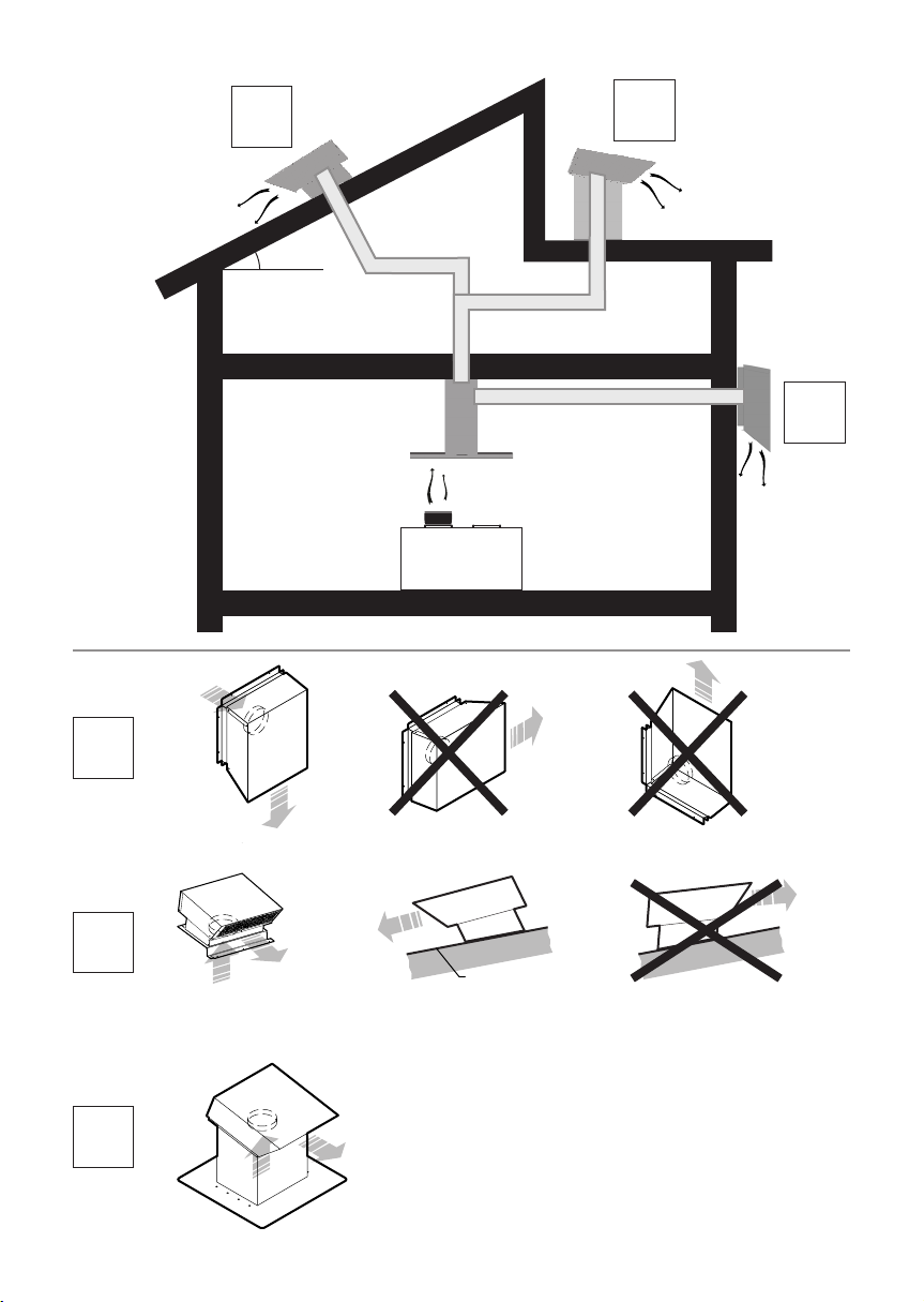
■La ventola è prevista solo per il montaggio su tetti di tegole. Il tetto deve avere una
pendenza di almeno 10°.
■La ventola non deve essere montata su tetti piani o tetti di Eternit.
■Il montaggio deve essere eseguito solo da un operaio copritetto qualificato.
■La ventola deve essere montata almeno alla distanza di 2 m dalla cappa aspirante.
■Non installare la ventola murale esterna in prossimità di finestre, porte o terrazze.
■Installare la ventola murale esterna in un luogo:
- che escluda l’inquinamento acustico e con odori a danno di confinanti vicini;
- che consenta l’accesso per la manutenzione.
■I collegamenti a spina del cavo elettrico devono essere disposti all’interno dell’edificio.

4
■Collegare la cappa aspirante con la ventola solo con tubi tondi lisci Ø 150mm
utilizzando il minor numero di curve. Se necessario acquistare come accessorio
speciale un silenziatore supplementare per tubi da Ø 150 mm.
Peso 10 Kg.
Con riserva di modifiche costruttive per evoluzione tecnica.
Montaggio
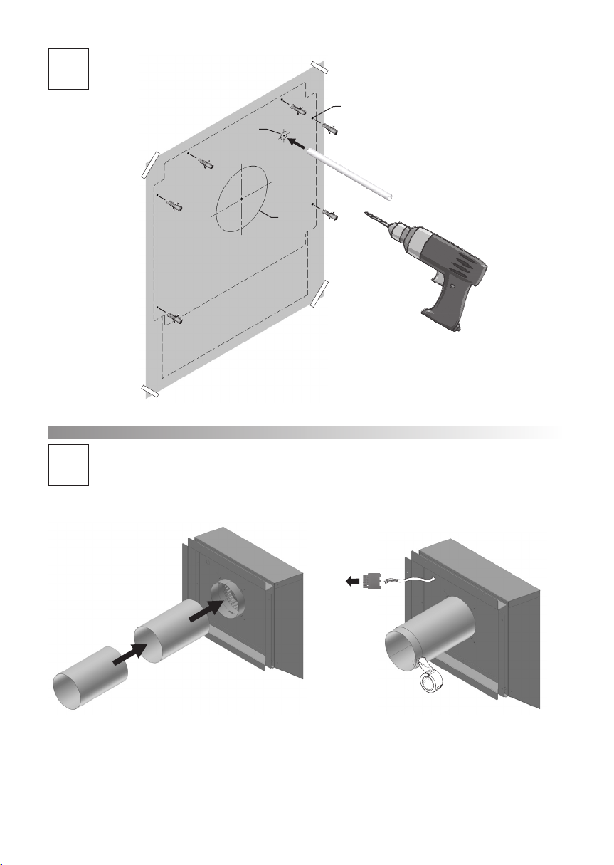
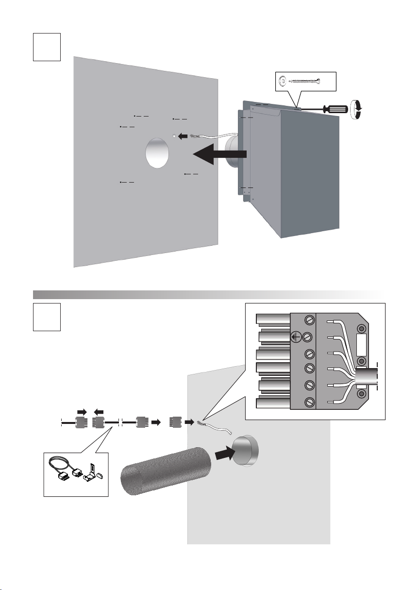
Montaggio ventola a parete (Fig. A)
1. Utilizzando la dima, tracciare nella parete i fori di fissaggio, il foro per il collegamento
del tubo dell’aria ed il foro per il collegamento del tubo elettrico.
2. Praticare i fori nel muro con mezzi idonei.
3. Collegare il tubo per l’aria alla ventola sigillandolo opportunamente.
4. Infilare nel tubo in plastica fornito il cavo elettrico della ventola e ricollegarlo come
indicato nella sezione allacciamento elettrico.
Montare la ventola fissandola con le viti facendo attenzione ad orientare la griglia di
uscita aria verso il basso.
5. Eseguire il collegamento dei tubi tra ventola e cappa aspirante sigillando
opportunamente i raccordi.
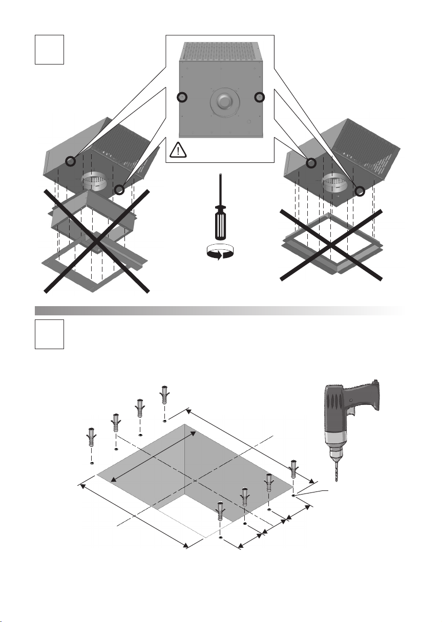
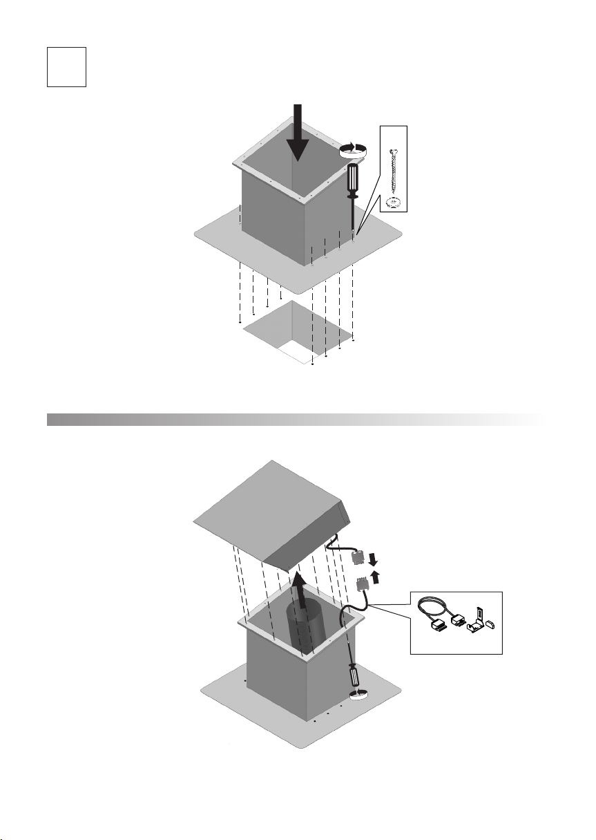
Montaggio ventola a tetto (Fig. B-C)
1. Rimuovere la copertura del tetto dalla zona di montaggio.
2. Montare la ventola fissandola con le viti facendo attenzione ad orientare la griglia di
uscita aria verso il basso.
3. Applicare nuovamente la copertura del tetto.
4. Impermeabilizzare il tetto.
5. Eseguire il collegamento dei tubi tra ventola e cappa aspirante sigillando
opportunamente i raccordi.

Allacciamento elettrico
Eseguire i collegamento elettrico tramite la spina di alimentazione.
Per motivi di sicurezza, la copertura supplementare della spina deve essere sempre
collegata e chiusa.
Se necessario, sono disponibili come accessorio prolunghe elettriche di lunghezza 5 m.
Se si utilizza un cavo di prolunga supplementare, la carcassa della ventola deve essere
collegata a terra dall’esterno da un’elettricista specializzato.
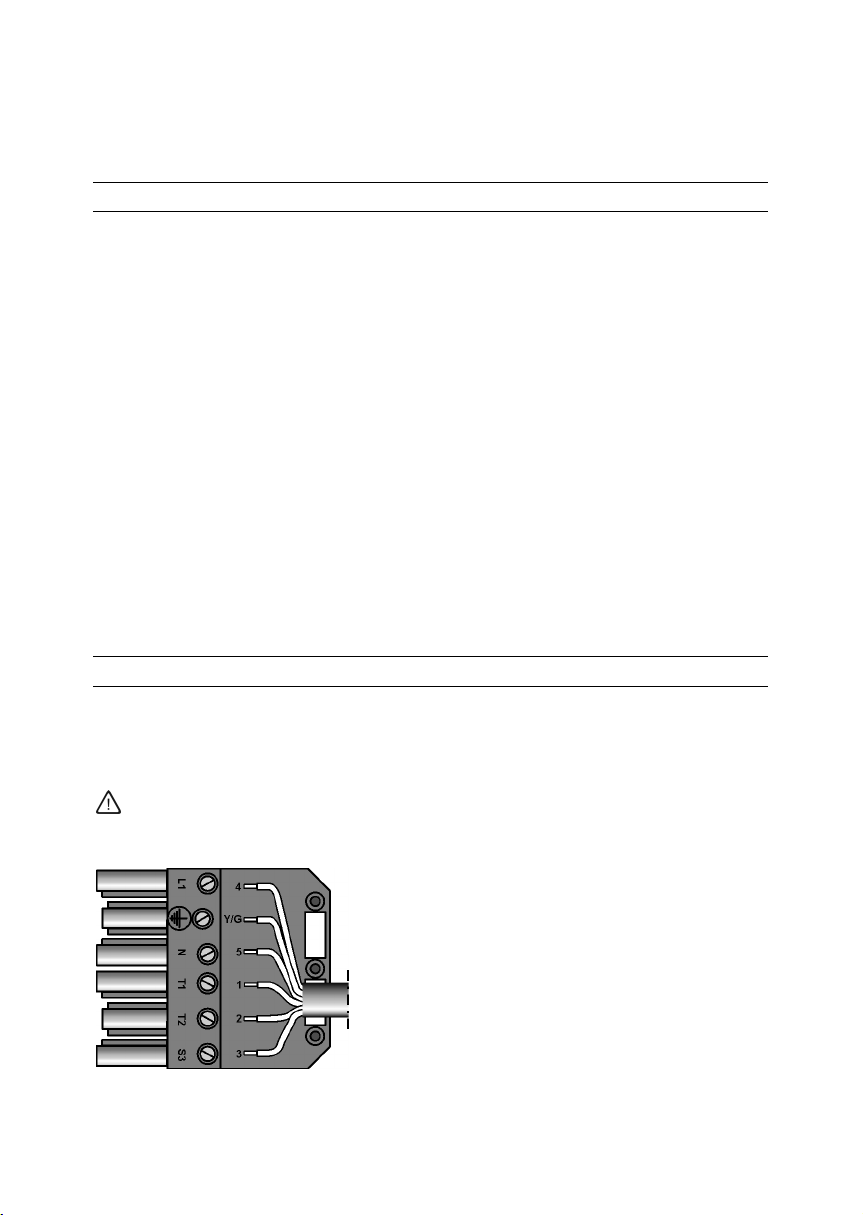
Cavo n° 4 nel polo L1 = velocità 4
Cavo giallo verde al polo di terra
Cavo n° 5 nel polo N = comune (N)
Cavo n° 1 nel polo T1 = velocità 1
Cavo n° 2 nel polo T2 = velocità 2
Cavo n° 3 nel polo S3 = velocità 3
Istruzioni di sicurezza
Controllare regolarmente se l’aria può uscire regolarmente dalla ventola. E’ vietato
chiudere la griglia di uscita dell’aria anche in modo parziale oppure permettere che sia
ostruita da piante.
Se il cavo di alimentazione dell’apparecchio viene danneggiato, deve essere sostituito
dalla casa produttrice dal suo servizio assistenza oppure da una persona specializzata.
Pulizia e manutenzione
Usare un detergente per l’acciaio inox delicato, non abrasivo.
Non pulire le superfici in acciaio inox con spugne dure né con detergenti contenenti
sabbia, soda, acido o cloro.
5

6
Important information
This appliance conforms to the relevant safety regulations.
The installation, the connection to the electrical net and repairs should be carried out only
by qualified specialists.
Improperly executed repairs can give rise to significant hazards for the user.
For repair and care always disconnect the motor from electricity by pulling out the plug
from the hood or by disconnecting the hood from the electricity.
Old appliances are not worthless rubbish. Valuable raw materials can be reclaimed by
recycling old appliances. Before disposing of your old appliance render it unusable.
Your received your new appliance in a protective shipping carton. All packaging materias
are environmentally friendly and recyclable. Please contribute to a better environment by
disposing of packaging materials in an environmentally friendly manner.
Please ask your dealer or inquire at your local authority about current means of disposal.
Prior to installation
When the extractor hood is operated in exhaust-air mode simultaneously with a different
burner which also makes use of the same chimney (such as gas, oil or coal-fired heaters,
continuous-flow heaters, hot-water boilers) care must be taken to ensure that there is
adequate supply of fresh air which will be needed by the burner for combustion.
Safe operation is possible provided that the underpressure in the room where the burner
is installed does not exceed 4 Pa (0,04mbar).
This can be achieved if combustion air can flow through non lockable openings, e.g. in
doors, windows and via the air-intake/exhaust-air wall box or by other technical
measures, such as reciprocal interlocking.
If the air intake is inadeguate, there is a risk of poisoning from combustion gases which
are drawn back into the room.
Pay special attention to the following warnings:
■The fan is designed for installation on sloping tiled roofs only. The slope of the roof
must be at least 10°.
■The fan must not be installed on flat roof or Eternit roof.
■The fan must be installed by qualified roofer only.
■The fan must be attached at least 2 m from the extractor hood.
■Do not attach the outer wall fan near windows, doors or patios.
■When attaching the outer wall fan, ensure that:
- residents and neighbours are not disturbed by noise and odours,
- it is accessibile for maintenance and repairs.
■The plug and socket connections of the electric cables must be located inside the
building.
■Connect the cooker hood with the fan only by round smooth pipes with Ø 150mm
and using as less bends as possible in the pipes. If necessary buy a special accessory
called silencer for pipes Ø 150 mm.
Weight 10 Kg.
We reserve the right to construction changes within the context of technical
development.
Installation
Installation of the fan on the wall (Fig.A)
1. Using the template, mark the fixing points on the wall, mark the hole for the air pipe
connection and the hole for the electric pipe connection.
2. Drill the holes on the wall with suitable means.
3. Connect the air pipe to the fan, sealing this in a proper way.
4. Slide in the plastic pipe supplied, the electrical cable of the fan and reconnect like
shown in the section electrical connection.
Mount the fan fixing this with the screws and paying attention to the exit grille which
should be placed to the bottom.
5. Connect the pipes between fan and hood, sealing the connections in proper way.
Installation of the fan on the roof (Fig.B-C)
1. Remove the roof covering from the installation area.
2. Insert the fan and screw it into position paying attention to the exit grille which
should be posioned to the bottom.
3. Re-attach the roof covering.
4. Seal the roof.
5. Connect the pipes between fan and hood, and seal the connections in proper way.
Electrical connection
Make the electrical connection by plug.
For security reason, the additional cover of the plug must always be connected and
closed.
If necessary we have some extension cable available as accessories in a length of 5 m.
If an additional extension cable is required, the exterior of the fan housing must be
earthed by a skilled electrician before the housing is screwed in position.
Wire n° 4 in the pole L1 = speed 4
Wire yellow green to the earh pole
Wire n° 5 in the pole N = common (N)
Wire n° 1 in the pole T1 = speed 1
Wire n° 2 in the pole T2 = speed 2
Wire n° 3 in the pole S3 = speed 3
7

8
Safety instructions
Regularly check that air can flow freely out of the fan. It is forbidden to obstruct he air
outlet grille in a partial way or to cover it with plants.
If the connecting cable of the appliance is damaged, the cable must be replaced by the
manufacturer or his customer service or a similarly qualified person in order to prevent
seriuos injury to the user.
Cleaning and Care
Use a mild non-abrasive stainless steel clener.
Do not use any of the following to clean stainless steeel surfaces: abrasive sponges,
cleaning agents containing sand, soda, acid and chloride!

9
Wichtige Hinweise
Dieses Gerät entspricht den einschlägigen Sicherheitsbestimmungen.
Montage, Anschluss und Reparaturen dürfen nur von Fachkräften durchgeführt werden,
ansonsten können Gefährdungen für den Benutzer entstehen.
Zur Reparatur und Wartung muss das Gebläse stromlos gemacht werden. Hierzu die
Steckverbindung des Elektrokabels zur Dunstabzugshaube trennen, oder die
Netztanschlussleitung der Dunstabzugshaube vom Stromnetz trennen.
Altgeräte sind kein wertloser Abfall. Durch umweltgerechte Entsorgung können wertvolle
Rohstoffe wiedergewonnen werden.
Bevor Sie das Altgerät entsorgen, machen Sie es unbrauchbar
Ihr neues Gerät wurde auf dem Weg zu Ihnen durch die Verpackung geschützt. Alle
eingesetzten Materialien sind umweltverträglich und wieder verwertbar. Bitte helfen Sie
uns und entsorgen Sie die Verpackung umweltgerecht.
Über aktuelle Entsorgungswege informieren Sie sich bitte bei Ihrem Fachhändler oder bei
Ihrer Gemeindeverwaltung.
Vor der Montage
Bei Abluftbetrieb der Dunstabzugshaube und gleichzeitigem Betrieb schornsteinabhängiger
Feuerungen (wie z.B. Gas, ÖL oder Kohleheizgeräte, Durchlauferhitzer,
Warmwasserbereiter) muss für ausreichende Zuluft gesorgt werden, die von der
Feuerstätte zur Verbrennung benötigt wird.
Ein gefahrloser Betrieb ist möglich, wenn der Unterdruck im Aufstellraum der Feuerstätte
von 4 Pa (0,04 mbar) nicht überschnitten wird.
Dies kann erreicht werden, wenn durch nicht verschließbare Öffnungen, z.B. in Türen,
Fenstern und in Verbindung mit Zuluft/Abluftmauerkasten oder durch andere techn.
Maßnahmem, wie gegenseitige Verriegelung o.ä die Verbrennungsluft nachströmen kann.
Bei nicht ausreichender Zuluft besteht Vergiftungsgefahr durch zurückgesaugte
Verbrennungsgase.
Bitte beachten Sie speziell folgenden Hinweise
■Das Gebläse ist nur für die Montage auf schrägen Ziegeldächern vorgesehen. Die
Dachschräge muss mindestens 10° sein.
■Das Gebläse darf nicht auf Flachdächern oder Eternitdächern montiert werden.
■Die Montage darf nur von einem ausgebildeten Dachdecker ausgeführt werden.
■Das Gebläse muss mindestens 2 mt entfernt von der Dunstabzugshaube montiert
werden.
■Das Gebläse nicht in der Nähe von Fenstern, Türen oder Terassen montieren.
■Das Gebläse an einer Stelle montieren:
- das Geräusch und Geruchsbelästigung von Anwohnern und Nachbarn ausschließt,
- Die Zugänglichkeit für Wartung und Reparatur ermöglicht.
■Die Steckverbindungen der Elektrokabel müssen innerhalb des Gebäudes sein.
10
■An den Verbindungsrohren zur Dunstabzugshaube darf keine Reduzierung von Ø 150
mm vorgenommen werden. Einen zusätzliche Schalldämpfer für Rohr150 Ø mm
können Sie beim Fachhandel als Sonderzubehör erwerbern.
Gewicht 10 Kg.
Konstruktionänderungen Im Rahmen der technischen Entwicklung bleiben vorenthalten.
Montage
Montage an der Wand (Abb. A)
1. Mit der Schablone zeichen Sie in der Wand die Befestigunslöcher, das Loch für die
Verbindung des Luftrohrs und das Loch für die Verbindung des elektrischen Kabels an.
2. Machen Sie die Löcher in der Wand mit geeigneten Werkzeugen.
3. Verbinden Sie das Luftrohr an das Gebläse und richtig abdichten.
4. In das gelieferten Kunstoffsrohr den elektrischen Kabel des Gebläses einführen und die
Verbindung wieder herstellen wie im Abschnitt Elektrischer Anschluss gezeigt.
Gebläse einsetzten und festschrauben, Luftaustritt nach unten.
5. Rohrverbindung vom Gebläse zur Dunstabzugshaube herstellen und die Verbindungen
richtig abdichten.
Montage am Dach (Abb. B-C)
1. Dacheindeckung im Montagebereich entfernen.
2. Gebläse einsetzten und festschrauben, Luftaustritt nach unten.
3. Dacheindeckung wieder anbringen.
4. Dach abdichten.
5. Rohrverbindung und elektrische Verbindung vom Gebläse zur Dunstabzugshaube
herstellen und die Verbindungen richtig abdichten.

Elektrischer Anschluss
Elektrische Verbindung immer durch Stecker machen.
Für Sicherheitsgrunden muss die zusätzliche Bedeckung vom Stecker immer
angeschlossen und zu sein.
Als Zubehör sind Verlängerungskabel erhältlich mit 5 mt Länge.
Wird ein zusätzliches Verlängerungskabel benötigt, muss das Gehäuse durch eine
Elektro-fachkraft geerdet sein.
Kabel nr. 4 im Pol L1 = Laufstufe 4
Gelb-Grünes Kabel im ErdungsPol
Kabel nr. 5 im Pol N = (N)
Kabel nr. 1 Im Pol T1 = Laufstufe 1
Kabel nr. 2 im Pol T2 = Laufstufe 2
Kabel nr. 3 im Pol S3 = Laufstufe 3
Sicherheitshinweise
Prüfen Sie regelmäßig ob die Luft problemlos aus dem Gebläse austreten kann. Die
Luftaustrittsgitter darf nicht zugestellt sein, oder durch Pflanzen zugewachsenen sein.
Wenn die Anschlusskabel dieses Gerätes beschädigt wird, muss sie durch den Hersteller
oder seinen Kundendienst oder eine ähnlich qualifizierte Person ersetzt werden, um
Gefährdung zu vermeiden.
Reinigung und Pflege
Verwenden Sie einen milden nicht scheuernden Edelstahlreiniger.
Edelstahloberflächen nicht mit kratzenden Schwämmen und nicht mit sand-soda-säure
oder chloridhaltigen Putzmitteln reinigen.
11
BC
A
A
B
C
Uscita/Outlet
Entrata/Inlet
Ø 150
Entrata/Inlet
Ø 150
Uscita/Outlet
Entrata/Inlet
Ø 150
Uscita/Outlet
min 10°
min 10°
M1
A
M2
A
¨8
¨ 165
¨20
1
3
5
2
4
M3
A
M4
A
6
7
x6
8
9
10
CAPPA
HOOD
11
2
T2
3
S3
Y/G
4
1
5
L1 T1N
optional L. 5m

M2
M1
340 (X)
240 (Y)
340
B
B
1
2
2

M4
M3
x6
B
B
3
4
5

M5
CAPPA
HOOD
B
6
7
optional L. 5m
M1
C
M2
C
¨8
360
290
2
425
80 80 80
1
Non rimuovere le viti!
Don’t remove the screws!
M3
C3
5
4x8
6
7
optional L. 5m
M4

06067714 0114
Table of contents
Languages:
Popular Ventilation Hood manuals by other brands

Ancona
Ancona AN-1280 User instructions

Zanussi
Zanussi Supertredil 640041 Brochure & specs

Westinghouse
Westinghouse QR061W owner's manual

Jenn-Air
Jenn-Air JXU9130WP Installation Instructions and Use & Care Guide

Whirlpool
Whirlpool UXT4030AD Installation Instructions and Use & Care Guide

ILVE
ILVE Majestic AM70 Use and Maintenance Installation manual


