Fiore FI310 User manual

PB
1
™
COOK TOP
INSTALLATION
AND
OPERATING
INSTRUCTIONS
FI310/FI320/
FI640/FI850/FI950

2
3
BEFORE INSTALLING YOUR FIORE™ COOK TOP
PLEASE READ THE COMPLETE MANUAL CAREFULLY
INTENDED FOR DOMESTIC KITCHEN USE ONLY
IMPORTANT:
Prior to assembly please inspect your Fiore™ product. Please report any damage of the product to your local ven-
dor before installation. Any claims for damage visible or hidden must be made immediately in order for the carrier
to assume full responsibility and absorb any associated costs. If damage or defect is discovered DO NOT IN-
STALL your Fiore product. Any claimed damage or defect to the nish of the product after the product has been
installed will be excluded from any manufacturer warranty.
ATTENTION:
1. All electrical and installation work must be done by a licensed contractor who is familiar with all
applicable
building codes and standards in your
region.
2. If the supply cord is damaged, it must be replaced by the manufacturer, its service agent or a similarly qualied
person to avoid a hazard. Any modications that may be required to the electrical system for the installation of the
range hood must only be made by qualied electricians.
3. Be sure to SHUT-OFF MAIN BREAKER PANEL before servicing the cook
top.
4. Use your Fiore cook top only for its intended purpose. The manufacturer disclaims all liability for any other
use
of the
appliance.
5. Pay close attention to existing electrical wiring and other non-visible rough utilities when cutting or drilling
into
wall or
ceiling.
6. This unit must be
grounded.
SAFETY INFORMATION
BEFORE YOU BEGIN
READ THESE INSTRUCTIONS COMPLETELY AND CAREFULLY.
IMPORTANT — Save these instructions for local inspector’s
use.
IMPORTANT — Observe all governing codes and
ordinances
Note to Installer – Be sure to leave these instructions with the Consumer
Note to Consumer – Keep these instructions for future reference.
IMPORTANT
—
Check the leakage according to the installation instruction.
Product failure
due
to improper installation is not covered under the
Warranty

2
3
FOR YOUR SAFETY:
If the information in this manual is not followed exactly, a re, explosion or gas leak may result. It may cause prop-
erty damage, personal injury or death.
Do not store or use gasoline or other ammable vapors and liquids in the vicinity of this appliance.
WHAT TO DO IF YOU SMELL
GAS
Do not try to light any appliance. Do not touch any electrical switch; do not use any phone in your
build ing.
Immediately call your gas supplier from a neighbor’s phone. Follow the gas supplier’s
instructions.
If you cannot reach your gas supplier, call the re department.
Installation and service must be performed by a qualied installer, service agency or the gas supplier.
WA R N I N G
Disconnect all electrical power at the main circuit breaker or fuse box before
install ing.
Installation of this cooktop must comply with local codes or in the absence of local codes with the National
Fuel
Gas Code ANSI Z223.1/NFPA54 – Latest Edition ANSI
Z223.1/NFPA
Be sure your cooktop is installed properly by a qualied installer or service technician.
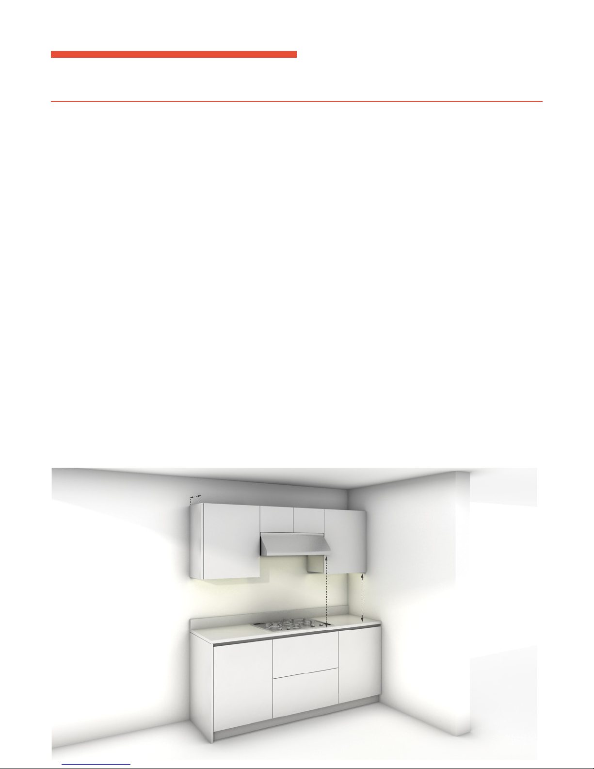
To eliminate reaching over surface burners, cabinet storage above burner should be
avoided
Do not install the unit near an outside door or where a draft may affect its
use.
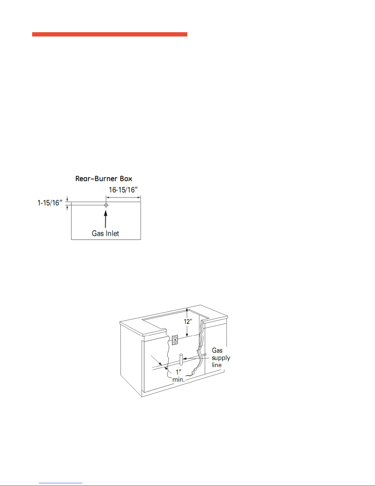
This product must be installed by a licensed plumber or gas tter.
When using ball-type gas shut-off valves, they shall be the T-handle
type.
If exible gas connector is being used, it must not exceed 3 feet.
Be sure the installation of this product in a mobile home must comply with the Manufactured Home Construc-
tion and Safety Standard, Title 24 CFR, Part 3280. If this standard does not apply, you must follow the standard
for
Manufactured Home Installations, ANSI A225.1 and Manufactured Home Installations, Sites and Commu-
nities, ANSI/NFPA 501A or with local codes. You can get a copy of the Federal Standard by Writing: Ofce of
Mobile Home Standards HUD, Building 451, 7th Street, S.W. Washington, D.C. 24010.

4
5
ELECTRICAL
REQUIREMENTS
This appliance must be supplied with the proper voltage, frequency and connected to an individual
properly
grounded branch circuit. The appliance must also be protected by a circuit breaker or fuse having amperage as
not-
ed on the rating
plate.
We recommend you to have the electrical wiring and hookup of your cooktop connected by a qualied electrician
After installation, have the electrician show you where your main cooktop disconnect is located. Check with
your
local utilities for electrical codes which apply in your area. Failure to wire your cooktop according to
governing
codes could result in a hazardous condition. If there are no codes, your cooktop must be wired and fused to
meet
the requirements of the National Electrical Code, ANSI/NFPA No. 70—Latest Edition. You can get a
copy
by
writing to: National Fire Protection Association Battery March Park Quincy, MA
02269
In Canada, your cooktop must be wired and fused to meet the requirements of the Canadian Electrical
Code.

4
5
COOK TOP INSTALLATION AND OPERATING INSTRUCTIONS
TABLE OF CONTENTS
INSTALLATION
PREPARATION
06
DIMENSIONS
AND
CLEARANCES
09
POWER
SUPPLY
LOCATIONS
10
INSTALLATION
INSTRUCTIONS
12
INSTALL
PRESSURE
REGULATOR
13
ASSEMBLE
BURNERS
AND
CHECK
IGNITION
14
LP
GAS
CONVERSION
16
SETTING
THE
MINIMUM
FLAME
20

6
7
INSTALATION PREPARATION
MODELS AVAILABLE
FI310 Series 11.8” Natural Gas/11.8”
LP
FI320 Series 11.8” Natural Gas/11.8”
LP
FI640 Series 22.8” Natural Gas/22.8”
LP
FI850 Series 22.8” Natural Gas/22.8”
LP
FI950 Series 30.3” Natural Gas/30.3”
LP
These models are factory set for either natural gas or LP gas operation. Be sure to order the
correct
model for
the installation
situation.
PARTS INCLUDED
2 Screws Regulator 2 Hold Down
Brackets
MATERIALS YOU MAY NEED
Joint Sealant Pipe Fittings Shut-Off Valve CSA-Approved Flexible Gas
Line
1/2″ Min. ID, 1/2″NPT Connection, 3-foot Maximum Length (Massachusetts
Only)
NOTE: Purchase new line, do not use previously used exible gas line.
TOOLS YOU WILL NEED FOR INSTALLATION
Pencil Phillips-Head Screwdriver Ruler or Straightedge Safety
Glasses
Saber Saw Pipe Wrench 1/8″ Drill Bit & Electric or Hand
Drill

6
7
INSTALATION PREPARATION
ADVANCE PLANNING
Refer to “Installation Preparation” for information on appropriate placement and necessary clearances when
plan
ning
installation.
Avoid placing cabinetry directly above cooktop when
possible.
If cabinetry is used above cooking
surface:
Use cabinets no more than 13″
deep.
Maintain 30″ minimum clearance between cooktop and unprotected cabinets directly above
cooktop.
If clearance is less than 30″, protect cabinet bottoms with ame-retardant millboard at least 1/4″ thick, or gypsum
board at least 3/16″ thick, covered with 28 gauge sheet steel or .02″ thick copper.
Clearance between cooktop and protected cabinetry must not be less than 24″.
An exhaust hood that projects at least 5″beyond front of cabinets can reduce risk of burns caused by reaching over
heated surface units.
Working areas adjacent to the cooktop should have 18″ minimum clearance between countertop and cabinet bot-
tom. A 36″or wider exhaust hood with 350 CFM or greater airow rating is recommended for use over this Mono-
gram cooktop.
Installation must complied with local codes. In the absence of local codes, the gas cooktop must complied with the
National Fuel Gas Code, ANSI Z223.1, latest edition.
Gas supply should be located near the opening for this cooktop (see Preparing the Opening and Gas Connection
sections of this manual). The supply should provide natural gas at 7″ of water column pressure (11″ of water col-
umn for LP gas) and a maximum of 14″ of water column for natural or LP gas.
The electric spark ignition feature for this model requires a 120V electrical power supply be located in the immedi-
ate vicinity of this cooktop (see Electrical Connections section of this manual).
18” min
30” min
13” max

8
9
PRE-INSTALATION CHECKLIST
1. When preparing cooktop opening, make sure the inside of the cabinet and the cooktop do not interfere with
each
other. (See section on preparing the
opening.)
2. Slide the cooktop out of the end of the box. Remove packaging materials, grate boxes, regulator and
literature
package from the cooktop before beginning
installation.
Use the shipping carton as a pad to protect customer countertops or ooring
3. Remove Installation Instructions from literature package and read them carefully before you begin. Be sure
to
place all literature, Owner’s Manual, Installations, etc. in a safe place for future
reference.
4. Make sure you have all the tools and materials you need before starting the installation of the
cooktop.
5. Your home must provide adequate electrical service tools to ensure your safety and to maintain your cooktop
as
well. (Refer to section on electrical
requirements.)
6. When installing cooktop in your home, make sure all local codes and ordinances are followed exactly as
stated.
7. Make sure the wall coverings, countertop and cabinets around the cooktop can withstand heat (up to
200°F)
generated by the
cooktop.

8
9
GAS SUPPLY AND PRESSURE REGULATOR
Gas supply: These cooktops are shipped from the factory set for either natural gas or LP gas. Check to be sure
you
have the correct cooktop for the type of gas being
used.
The pressure regulator must be connected in series with the manifold of the cooktop and must remain in
series
with the supply line regardless type of gas being
used.
The natural gas model is designed to operate at 5″ water column pressure. A regulator is required at the
natural
gas source to provide a minimum of 6″ water column to the cooktop
regulator
The liquid propane model is designed to operate at 10″ water column pressure. A regulator is
required
at the LP
Gas source to provide a minimum of 11″water column to the cooktop
regulator.
For ease of installation, if local codes permit the gas supply line into the cooktop should be 1/2″or 3/4″ ID exible
metal appliance connector with three to ve feet long.
NOTE:
Purchase new exible line. DO NOT USE OLD, PREVIOUSLY USED FLEXIBLE LINE
The gas inlet is located on the bottom of the burner box at the rear and
center.
Make gas connection through rear wall, or on cabinet oor at rear, as illustrated.
Install the house gas supply at least 1. from the back
wall.
Locate the electrical outlet 12. below the
countertop.

10
11
INSTALL PRESSURE REGULATOR
WARNING: Never reuse old exible connectors. The use of old exible connectors can cause gas leakage and per-
sonal injury. Always use new exible connectors when installing a gas appliance. To reduce the possibility of gas leakage,
apply Teon tape or a thread compound approved for use with LP or Natural gases to all threaded connections.
Screw the regulator onto the burner box bottom pipe connection. Make sure the top of the regulator is
facing
toward the cabinet front and the arrow on the back of the regulator points to the
cooktop.
OPTION: You can install a 90º elbow (not supplied) onto the gas inlet and route the gas connections to avoid
inter
ference when installed over an oven, with a downdraft vent, a warming drawer or other cabinetry
features.
Com-
plete the connection between the regulator and the shut-off
valve.
Before testing for leaks, make sure all burner knobs are in the OFF
position.
After connecting the cooktop to gas, check system for leakage with a manometer. If a manometer is not
available,
turn the gas supply on to the cooktop and use a liquid leak detector at all joints and connections to check for
leak
ing. Tighten all connections if necessary to prevent gas leakage in the cooktop or supply
line.
WARNING: Do not using ame to check for leaking.
Disconnect the cooktop and its individual shut-off valve from the gas supply piping system during any
pressure
testing of that system at test pressures greater than 1/2 psig (3.5
kPa).
Isolate the cooktop from the gas supply piping system by closing its individual shut-off valve during any
pressure
testing of the gas supply system at test pressures equal to or less than 1/2 psig (3.5
kPa).
CONNECT
ELECTRICAL
Check to make sure the receptacle is properly
grounded.
PLUG IN THE POWER
COR D.

10
11
Install a manual shut-off valve in the gas line in an easily accessible location outside the cooktop. Be sure you
know
how and where to shut off the gas supply to the cooktop. Install the electrical outlet 12″ below the
countertop.
ELECTRICAL CONNECTION:
This cooktop features pilotless electric ignition for energy savings and reliability. It operates on a 120 volt, 60
Hz
power supply. A separate circuit, protected by a 15 amp time delay fuse or circuit breaker, is
required.
A properly-grounded 3-prong receptacle should be located within reach of the cooktop’s four-foot power
cord.
IMPORTANT: (Please read carefully). FOR PERSON SAFETY, THIS APPLIANCE MUST BE
PROPER LY
GROUNDED.
The power cord of this appliance is equipped with a three-prong (grounding) plug which mates with a
standard
three-prong grounding wall receptacle to minimize the possibility of electric shock hazard from this
appliance.
The customer should have the wall receptacle and circuit checked by a qualified electrician to make sure
the receptacle is properly grounded and has correct polarity.
Where a standard two-prong wall receptacle is encountered, it is the personal responsibility and obligation of
the
customer to have it replaced with a properly grounded three-prong wall
receptacle.
Do Not, Under Any Circumstances, Cut Or Remove The Third (Ground) Prong From The Power
Cord.
Do not use an extension
cord.

12
13
DIMENSIONS AND CLEARANCES
Overall cooktop dimensions:
Use a 36″ or wider base cabinet.
Cut the opening in the countertop. To ensure accuracy, it is best to make a template for the opening. Make sure the
sides of the opening are parallel also rear and front cuts are exactly perpendicular to the sides.
Observe all minimum
clearances.
FI310
Series
FI640
Series
FI850/950
Series
Clearances Clearances Clearances
DIMENSIONS AND CLEARANCES
Observe all minimum clearances.
FI310 Series
Clearances
FI640 Series
Clearances
FI850/950 Series
Clearances
22"
5.9"
2.95"
19.29"
60cm cutting out
75
150
490
560
28.74"
5.9"
19.29"
2.95"
80
and
90cm cutting out
75
150 730
490
5.9" 11"
2.95"
19.29"
30cm cutting out
75
150
490
280

12
13
DIMENSIONS AND CLEARANCES
Observe all minimum clearances.
FI310 Series
Clearances
FI640 Series
Clearances
FI850/950 Series
Clearances
22"
5.9"
2.95"
19.29"
60cm cutting out
75
150
490
560
28.74"
5.9"
19.29"
2.95"
80
and
90cm cutting out
75
150 730
490
5.9" 11"
2.95"
19.29"
30cm cutting out
75
150
490
280
INSTALLATION INSTRUCTIONS
Remove the screws on the sides of the cooktop burner box. Use those screws to attach the side mounting
brackets.
Insert the cooktop centered into the cutout opening. Make sure the front edge of the countertop is parallel to
the
cooktop. Check clearances at the front, back and
sides.
FIGURE A
Secure the hold-down bracket to the cabinet sides with
screws.
Cut the opening in the countertop. To ensure accuracy it is
best
to
make a template (see Figure A) for the
opening.
Make sure the sides are parallel also rear and front cuts are
exactly
perpendicular to the sides. Observe all minimum
clearances
Please refer to your exact model number for the
correct
cut-out
dimensions
FIGURE B
Before inserting the cooktop into the opening in
the
coun-
tertop, remove the grates and burner caps, turn
the
cook-
top upside down and place the special foam
gasket
around
the bottom edge of the cooktop (see Figure B). It
is
im-
portant to x this gasket evenly, without gaps or
overlap-
ping, to prevent liquid seeping underneath the
cooktop.
After the foam gasket has been afxed, place
the
cooktop into the countertop (see Figure
C).
FIGURE C
Secure cooktop from underneath with the
supplied
clips
and screws (see Figure
D).
FIGURE D
INSTALLATION INSTRUCTI
FIGURE B
FIGURE A
FIGURE C FIGURE D
ONS
1. INSTALL THE COOKTOP
A Remove the screws on the sides of the cooktop burner box. Use those screws to attach the side mounting brackets.
B. Insert the cooktop centered into the cutout opening. Make sure the front edge of the countertop is parallel to the
cooktop. Check clearances at the front, back and sides.
Secure the hold-down bracket to the cabinet sides with screws.
Cut the opening in the countertop. To ensure accuracy it is best
to make a template (see Figure A) for the opening.
Make sure the sides are parallel also rear and front cuts are exactly
perpendicular to the sides. Observe all minimum clearances
Before inserting the cooktop into the opening in the
countertop, remove the grates and burner caps, turn the
cooktop upside down and place the special foam gasket
around the bottom edge of the cooktop (see Figure B). It is
important to fix this gasket evenly, without gaps or overlap-
ping, to prevent liquid seeping underneath the cooktop.
After the foam gasket has been affixed, place the
cooktop into the countertop (see Figure C).
Secure cooktop from underneath with the supplied
clips and screws (see Figure D).
28.74"
5.9"
19.29"
2.95"
80
and
90cm cutting out
75
150 730
490
Please refer to your exact model number for the correct
cut-out dimensions
Clip
Screw Slot

14
15
ASSEMBLE BURNERS AND CHECK IGNITION
The electrode of the electronic ignition system is positioned above the surface of the burner base. Do not remove
a
burner cap or touch the electrode of a burner while another is turned on. Damage or electrical shock may
occur.
The electrode of the electronic ignition system is positioned above the surface of the burner base. Do not remove
a
burner cap or touch the electrode of a burner while another is turned on. Damage or electrical shock may
occur.
Place burner heads over the burner base. Make sure the hole in the burner head is properly aligned with the
elec-
trode in the burner
base.
Place the burner caps on the burner heads. Make sure that the burner caps are properly seated on the burner
heads.
Burner cap properly seated Burner cap not properly
seated
Check
igniters.
Operation of the electric igniters should be tested after the cooktop and supply line have been carefully checked
for
leaks and the cooktop has been connected to the electrical
power.
Push and turn a burner valve to the LITE position. All spark igniters will make a series of sparks (ticking
sounds),
but only the burner turned to LITE will
light.
The burner should light when gas is available to the
burner.
Once the burner lights, it should be turned to another
position.
Test each valve separately until all burners have been
checked.
IMPORTANT: If the igniter electrodes continue to spark after all of the burners are lit, check that each burner
com-
ponent is assembled and properly
seated.

14
15
Burner
ignition.
Cooktop Spark Ignition—When you turn the cooktop knob to LITE, the spark igniter makes a series of
electric
sparks (ticking sounds) which light the burner. During a power failure, the burners will not light automatically. In
an
emergency, a cooktop burner may be lit with a match by following the steps
below.
WARNING: Lighting gas burners with a match is dangerous. You should match light the cooktop burners only
in
an
emergency.
Light a match and hold the ame near the burner you want to light. Wooden matches work
best.
Push in and turn the control knob slowly. Be sure you are turning the correct knob for the burner you are
lighting.
NOTE: If the burner does not light within ve seconds, turn the knob off and wait one minute before trying
again.
Turn on each burner. On LP models, ames should be blue in color but may have yellow tips. Natural gas
models
should have soft, blue ames. The burner ames should not utter or blow away from the burner. The ame
should
be no less than 1/4″ on the lowest setting and no greater than 1-1/2″ on highest
sett ing.
Burners should be checked
frequently.
WARNING: If you attempt to measure the ame, please use caution. Burns could
result.
OPER ATION
CHECKLIST
1. Make sure all controls are left in the OFF
position.
2. The serial plate for your cooktop is located on the bottom of the burner box. In addition to the model and serial
numbers,
it
tells you the ratings of the burners and the type of fuel and pressure the cooktop was adjusted for when it left the
factory.
3. When ordering parts, always include the serial number, model number and a code letter to ensure proper replacement
parts.
4. Check again to be sure all installation procedures have been
completed.

16
17
LP GAS CONVERSION
If sold outside the U.S. and
Canada:
WARNING: If you wish to use this product with Liqueed Petroleum (LP) gas containing greater than 10%
bu-
tane,
you must purchase the butane conversion
kit.
SAFTY INFORMATION
The pressure regulator and burner orices are set for natural gas
operation.
To convert this cooktop from natural gas operation to LP operation, the regulator and burner orices must be
convert-
ed.
LP burner orices are attached to the
regulator.
This appliance can be used with Natural Gas or LP/Propane Gas. It is shipped from the factory for use with Natural Gas. A
kit
for converting to LP gas is supplied with your appliance. The kit is marked “FOR LP/PROPANE GAS
CONVERSION”.
When the range is converted for Liquid Petroleum (LP) Gas, the LP gas supply is required to provide a minimum
of
10” to a maximum of 14” water column to the range
regulator.
CAUTION — The cooktop, as shipped from the factory, is set for use with its intended gas. If you wish to use
your cooktop with the alternate gas, you must rst replace the orices and convert the pressure
regulator.
WARNING — This conversion must be performed by a qualied installer or gas supplier in accordance
with
the manufacturer’s instructions and all codes and requirements of the authority having jurisdiction. Failure to
follow
instructions could result in serious injury or property damage. The qualied agency performing this work
assumes
responsibility for the
conversion.
CAUTION — The following adjustments must be made before turning on the burner. Failure to do so
could
result
in serious injury. Be sure pressure regulator has been converted as described in Step
1.

16
17
TOOLS YOU WILL NEED
1. ADJUST THE REGULATOR
A. Disconnect all electrical power at the main circuit breaker or fuse
box.
B. Shut off the gas supply to the appliance by closing the manual shut-off
valve.
C. Adjust the pressure regulator by doing the
following:
FIGURE A FIGURE
B
For Natural Gas usage the retainer pin will look like this.
(See Figure B)
FIGURE D
Unscrew the cap with a Crescent wrench.
(See Figure A)
Remove the retainer pin.
(See Figure C)
Proceed
to
reverse the retainer pin and place
it
back into the
regu-
lator cap. This
is
how the regulator pin looks for LP gas
usage.
(See Figure
D)
FIGURE E
5) Screw the regulator cap back into the regulator and
re-at-
tach the regulator to the nipple and are
union.
(See Figure
E)
FIGURE C

18
19
2. CHANGE BURNER NOzzLES
INSTALLATION TIP: First remove all nozzles and then start replacing them. This will help to prevent the
pos-
si-
bility that some may not be
replaced.
1. Remove the burner grates, burner caps and burner
heads.
2. Using a 7mm nut driver, remove the top burner nozzle. There are two nozzle per burner. The main orice is
locat-
ed below center of the burner, while the simmer nozzle is located higher beside the center of the
burner
Triple ring burner Rapid burner Semi-rapid burner Auxiliary
burner
IMPORTANT:
Orices must be located exactly as shown. Carefully read and observe each orice label for correct
location.
3. Install the proper nozzle in the exact locations as noted in the illustrations
above.
4. Return the natural gas nozzle to the bracket and reattach the bracket and the instruction sheet to the pressure
regu-
lator using the screw removed
previously.
5. Replace the burner bases, heads, caps and top
grates.
BURNER POSITION NOZZLE
DIAMETER
MINIMUM
PRESSURE
MAXIMUM
PRESSURE
RATE
( BT U/H )
Auxiliary Front Right 1 x 0.70 10” 14” 4,800
Semi-Rapid Rear Left & Right 1 x 0.80 10” 14” 6,500
Rapid Front Left 1 x 0.89 10” 14” 8,500
Triple Ring Center 5 x 0.56 10” 14” 15,500
ATTENTION: BE SURE TO REVIEW AND OBSERVE EACH NOZZLE FOR CORRECT LOCATION
AND POSITION - PLEASE REFER TO FIGURE F and G BELOW:
FIGURE F
TRIPLE RING BURNER AUXILARY BURNER
5 NOZZLES SEMI-RAPID BURNER
RAPID BURNER
1 NOZZLE EACH
FIGURE G
SCALE: 3" = 1'-0"
BURNER
Install the proper nozzles in the exact locations as noted in the illustrations above and the table below.
Replace the burner bases, heads, caps and top grates. Conrm burner caps are properly resting on the burner head.
LIQUID PRETROLEUM (LP) GAS NOZZLES
NOZZLES
56 5656
80
89 70
80
56
56
18 19
2. CHANGE bURNER NOZZLES
INSTA LLATION TIP: First remove all nozzles and then start replacing them. This will help to prevent the possi-
bility that some may not be replaced.
A. Remove the burner grates, burner caps and burner heads.
B. Using a 7mm nut driver, remove the top burner nozzle. There are two nozzle per burner. The main orice is locat-
ed below center of the burner, while the simmer nozzle is located higher beside the center of the burner
Triple ring burner Rapid burner Semi-rapid burner Auxiliary burner
IMPORTANT:
Orices must be located exactly as shown. Carefully read and observe each orice label for correct location.
C. Install the proper nozzle in the exact locations as noted in the illustrations above.
D. Return the natural gas nozzle to the bracket and reattach the bracket and the instruction sheet to the pressure regu-
lator using the screw removed previously.
E. Replace the burner bases, heads, caps and top grates.

18
19
LIqUID PRETROLEUM (LP) GAS NOzzLES
BURNER POSITION NOZZLE
DIAMETER
MINIMUM
PRESSURE
MAXIMUM
PRESSURE
R ATE
( BT U/H )
Auxiliary
Front
Right
1 x
0.70 10” 14” 4,800
Semi-Rapid
Rear Left &
Right
1 x
0.80 10” 14” 6,500
Rapid
Front
Left
1 x
0.89 10” 14” 8,500
Triple
Ring Center
5 x
0.56 10” 14” 15,500
ATTENTION: BE SURE TO REVIEW AND OBSERVE EACH NOZZLE FOR CORRECT
LOCATION
AND POSITION - PLEASE REFER TO FIGURE F and G
BE L OW:
FIGURE F
TRIPLE RING
BURNER
AUXILARY
BURNER
5
NOZZLES
SEMI-RAPID
BURNER
RAPID
BURNER
1 NOZZLE
EACH
FIGURE G
BURNER POSITION NOZZLE
DIAMETER
MINIMUM
PRESSURE
MAXIMUM
PRESSURE
RATE
( BT U/H )
Auxiliary Front Right 1 x 0.70 10” 14” 4,800
Semi-Rapid Rear Left & Right 1 x 0.80 10” 14” 6,500
Rapid Front Left 1 x 0.89 10” 14” 8,500
Triple Ring Center 5 x 0.56 10” 14” 15,500
ATTENTION: BE SURE TO REVIEW AND OBSERVE EACH NOZZLE FOR CORRECT LOCATION
AND POSITION - PLEASE REFER TO FIGURE F and G BELOW:
FIGURE F
TRIPLE RING BURNER AUXILARY BURNER
5 NOZZLES SEMI-RAPID BURNER
RAPID BURNER
1 NOZZLE EACH
FIGURE G
SCALE: 3" = 1'-0"
BURNER
Install the proper nozzles in the exact locations as noted in the illustrations above and the table below.
Replace the burner bases, heads, caps and top grates. Conrm burner caps are properly resting on the burner head.
LIQUID PRETROLEUM (LP) GAS NOZZLES
NOZZLES
56 5656
80
89 70
80
56
56
Install the proper nozzles in the exact locations as noted in the illustrations above and the table
below.
Replace the burner bases, heads, caps and top grates. Conrm burner caps are properly resting on the burner
head.

20
21
SETTING THE MINIMUM FLAME
The ame on the small output is regulated by the factory. When the injectors have been replaced or there are
special
mains pressure conditions, it may be necessary to regulate the minimum ame again. The operations necessary to
set
the minimum ame are as
following:
1. Light the
burner;
2. Turn the knob to the minimum
position;
3. Take out the knob (and gasket if there is
one);
Using a thin blade screwdriver to turn by-pass screw located in the brass shaft as shown right.Turn the by
pass
screw
fully clockwise then turn it anti-clockwise 1/4 turn for the Triple ring and 1/8turn for all other burndrs.
The
result should be a small,stable ame which is uniform around the entire burner ring.If not,turn the by-pass
screw
anti-clockwise until satised with the
ame
Put the knob back on and turn it quickly from the maximum position to the minimum position, checking that
the
ame does not go out
;
For burners with safety valve make sure that the regulation obtained is sufcient to maintain heating of the
ther-
mocouple. If it is not, increase the
minimum.
SETTING THE MINIMUM FLAME
The ame on the small output is regulated by the factory. When the injectors have been replaced or there are special
mains pressure conditions, it may be necessary to regulate the minimum ame again. The operations necessary to set
the minimum ame are as following:
Light the burner;
Turn the knob to the minimum position;
Take out the knob (and gasket if there is one);
Using a thin blade screwdriver to turn by-pass screw located in the brass shaft as shown right.Turn the by pass
screw fully clockwise then turn it anti-clockwise 1/4 turn for the Triple ring and 1/8turn for all other burndrs. The
result should be a small,stable ame which is uniform around the entire burner ring.If not,turn the by-pass screw
anti-clockwise until satised with the ame
Put the knob back on and turn it quickly from the maximum position to the minimum position, checking that the
ame does not go out ;
For burners with safety valve make sure that the regulation obtained is sufcient to maintain heating of the ther-
mocouple. If it is not, increase the minimum.
This manual suits for next models
4
Table of contents