Fire-Lite MS-4012 User manual

1234567890123456789012345678901212345678901234567890123456789012123456789012
1
23456789012345678901234567890121234567890123456789012345678901212345678901
2
1
23456789012345678901234567890121234567890123456789012345678901212345678901
2
1
23456789012345678901234567890121234567890123456789012345678901212345678901
2
1
23456789012345678901234567890121234567890123456789012345678901212345678901
2
1
23456789012345678901234567890121234567890123456789012345678901212345678901
2
1
23456789012345678901234567890121234567890123456789012345678901212345678901
2
1
23456789012345678901234567890121234567890123456789012345678901212345678901
2
1
23456789012345678901234567890121234567890123456789012345678901212345678901
2
1
23456789012345678901234567890121234567890123456789012345678901212345678901
2
1
23456789012345678901234567890121234567890123456789012345678901212345678901
2
1
23456789012345678901234567890121234567890123456789012345678901212345678901
2
1
23456789012345678901234567890121234567890123456789012345678901212345678901
2
1
23456789012345678901234567890121234567890123456789012345678901212345678901
2
1
23456789012345678901234567890121234567890123456789012345678901212345678901
2
1
23456789012345678901234567890121234567890123456789012345678901212345678901
2
1
23456789012345678901234567890121234567890123456789012345678901212345678901
2
1
23456789012345678901234567890121234567890123456789012345678901212345678901
2
1
23456789012345678901234567890121234567890123456789012345678901212345678901
2
1
23456789012345678901234567890121234567890123456789012345678901212345678901
2
1
23456789012345678901234567890121234567890123456789012345678901212345678901
2
1
23456789012345678901234567890121234567890123456789012345678901212345678901
2
1
23456789012345678901234567890121234567890123456789012345678901212345678901
2
1
23456789012345678901234567890121234567890123456789012345678901212345678901
2
1
23456789012345678901234567890121234567890123456789012345678901212345678901
2
1
23456789012345678901234567890121234567890123456789012345678901212345678901
2
1
23456789012345678901234567890121234567890123456789012345678901212345678901
2
1
23456789012345678901234567890121234567890123456789012345678901212345678901
2
1
23456789012345678901234567890121234567890123456789012345678901212345678901
2
1
23456789012345678901234567890121234567890123456789012345678901212345678901
2
1
23456789012345678901234567890121234567890123456789012345678901212345678901
2
1
23456789012345678901234567890121234567890123456789012345678901212345678901
2
1
23456789012345678901234567890121234567890123456789012345678901212345678901
2
1
23456789012345678901234567890121234567890123456789012345678901212345678901
2
1
23456789012345678901234567890121234567890123456789012345678901212345678901
2
1
23456789012345678901234567890121234567890123456789012345678901212345678901
2
1
23456789012345678901234567890121234567890123456789012345678901212345678901
2
1
23456789012345678901234567890121234567890123456789012345678901212345678901
2
1
23456789012345678901234567890121234567890123456789012345678901212345678901
2
1
23456789012345678901234567890121234567890123456789012345678901212345678901
2
1
23456789012345678901234567890121234567890123456789012345678901212345678901
2
1
23456789012345678901234567890121234567890123456789012345678901212345678901
2
1
23456789012345678901234567890121234567890123456789012345678901212345678901
2
1
23456789012345678901234567890121234567890123456789012345678901212345678901
2
1
23456789012345678901234567890121234567890123456789012345678901212345678901
2
1
23456789012345678901234567890121234567890123456789012345678901212345678901
2
1
23456789012345678901234567890121234567890123456789012345678901212345678901
2
1
23456789012345678901234567890121234567890123456789012345678901212345678901
2
1
23456789012345678901234567890121234567890123456789012345678901212345678901
2
1
23456789012345678901234567890121234567890123456789012345678901212345678901
2
1
23456789012345678901234567890121234567890123456789012345678901212345678901
2
1
23456789012345678901234567890121234567890123456789012345678901212345678901
2
1
23456789012345678901234567890121234567890123456789012345678901212345678901
2
1
23456789012345678901234567890121234567890123456789012345678901212345678901
2
1
23456789012345678901234567890121234567890123456789012345678901212345678901
2
1
23456789012345678901234567890121234567890123456789012345678901212345678901
2
1
23456789012345678901234567890121234567890123456789012345678901212345678901
2
1
23456789012345678901234567890121234567890123456789012345678901212345678901
2
1
23456789012345678901234567890121234567890123456789012345678901212345678901
2
1
23456789012345678901234567890121234567890123456789012345678901212345678901
2
1
23456789012345678901234567890121234567890123456789012345678901212345678901
2
1
23456789012345678901234567890121234567890123456789012345678901212345678901
2
1
23456789012345678901234567890121234567890123456789012345678901212345678901
2
1
23456789012345678901234567890121234567890123456789012345678901212345678901
2
1
23456789012345678901234567890121234567890123456789012345678901212345678901
2
1
23456789012345678901234567890121234567890123456789012345678901212345678901
2
1
23456789012345678901234567890121234567890123456789012345678901212345678901
2
1
23456789012345678901234567890121234567890123456789012345678901212345678901
2
1
23456789012345678901234567890121234567890123456789012345678901212345678901
2
1
23456789012345678901234567890121234567890123456789012345678901212345678901
2
1
23456789012345678901234567890121234567890123456789012345678901212345678901
2
1
23456789012345678901234567890121234567890123456789012345678901212345678901
2
1
23456789012345678901234567890121234567890123456789012345678901212345678901
2
1
23456789012345678901234567890121234567890123456789012345678901212345678901
2
1
23456789012345678901234567890121234567890123456789012345678901212345678901
2
1
23456789012345678901234567890121234567890123456789012345678901212345678901
2
1
23456789012345678901234567890121234567890123456789012345678901212345678901
2
1
23456789012345678901234567890121234567890123456789012345678901212345678901
2
1
23456789012345678901234567890121234567890123456789012345678901212345678901
2
1
23456789012345678901234567890121234567890123456789012345678901212345678901
2
1
23456789012345678901234567890121234567890123456789012345678901212345678901
2
1
23456789012345678901234567890121234567890123456789012345678901212345678901
2
1
23456789012345678901234567890121234567890123456789012345678901212345678901
2
1234567890123456789012345678901212345678901234567890123456789012123456789012
Instruction Manual for the
MS-4012/4024 and CMS-4012/4024
Fire Alarm Control Panels
R
12 Clintonville Road, Northford, CT 06472
Phone: (203) 484-7161 FAX: (203) 484-7118
Document 15586
5/11/93 Revision:E
P/N 15586:E ECN 93-119

215586 Rev E 5/14/93 P/N 15586:E

15586 Rev E 5/14/93 P/N 15586:E 3
Table of Contents
Note: Thisinstructionmanual coverspanelslisted byUL(MS-4012 andMS-4024)and byULC(CMS-4012 and
CMS-4024).Forsimplicity,thisdocumentrefers tothesepanelsas the"4012"(forthe 12-voltMS-4012andCMS-
4012 control panels)and the "4024" (forthe 24-voltMS-4024 andCMS-4024 controlpanels).
Inside Back Cover
Page
Table of Figures 4
1.0 Fire Alarm Control System 7
1.1 Standard Features 7
1.2 Optional Features 7
2.0 Controls and Indicators 8
2.1 Control Switches 8
2.2 Status Indicators 9
3.0 Installation Instructions 10
3.1 General 10
3.2 Initiating Circuits 10
3.3 Output Circuits 11
3.4 Power 12
3.5 Optional Modules 13
4.0 Periodic Testing 20
4.1 Notification 20
4.2 System Test 20
4.3 Zone Test 20
4.4 Initiating Device Test 20
4.5 Supervisory Test 20
4.6 Trouble Test 21
4.7 Battery Test 21
4.8 Test Completion 21
5.0 Troubleshooting Guide 22
5.1 Control Panel Checkup 23
Appendix A: Specifications 26
Appendix B: Power Calculations 28
Quick Reference Sheets

415586 Rev E 5/14/93 P/N 15586:E
Table of Figures
Page
2A Dress Panel 8
3A Zone Wiring 10
3B Dress Panel Terminal Guide 11
3C Indicating Circuit Wiring Diagram 11
3D Typical End of Line Relay Connection 12
3E AC Connections 12
3F Battery and Meter Connections 13
3G Remote Zone Annunciator Installation 14
3H Zone Relay Module Connections 15
3I General Alarm and Trouble Module Connections 16
3J Transmitter Module Connections 17
3K McCulloh-Type Transmitter Connection 18
3L Basic System Wiring Diagram 19
3M Battery Charger Check Procedure 24

15586 Rev E 5/14/93 P/N 15586:E 5
National Fire Protection Association (NFPA) Standards:
71 Signaling Systems for Central Station Service
72 Local Protective Signaling Systems
72 Auxiliary Protective Signaling Systems
72 Remote Station Protective Signaling Systems
72 Proprietary Protective Signaling Systems
Underwriter's Laboratories (UL) listed as a
Fire Protective Signaling System - Standard 864
Underwriter's Laboratories of Canada (ULC) listed
Standard CAN/ULC - S527 - M87
California State Fire Marshall (CSFM) listed
CSFM File Number: 7165-075:130
Bureau of Standards and Appeals listed
MEA Resolution Number: 578-81-SA
MEAMEA
MEAMEA
MEA
The MS-4012/4024 and CMS-4012/4024 Fire Alarm Control Panels are suitable for service
under the following standards:
For Compatible Notification Appliances, 2 and 4-wire smoke detectors and door holders, refer to the
Fire Lite Device Compatibility Document, 15384.

615586 Rev E 5/14/93 P/N 15586:E
Eachoptionalmodulelistedinthismanualas"40xx"isofferedin12and24-voltversions.The"XX"represents
either "12" or "24" volts DC.
Each module is further distinguished by its respective two letter abbreviation (such as TM for Transmitter
Module).
When received, the actual module boards will be marked as "MS4000 - 40xx" followed by a one letter
abbreviation and the letter "B" (
for board
).
For instance:
To order a 24-volt General Alarm and Trouble Module, order a "4024AT".
The module received will be marked "MS4000 - 40xxAB."
The voltage of a particular module is inked
on the bottom side of the PC board
A Packaging Note

15586 Rev E 5/14/93 P/N 15586:E 7
1.0 Fire Alarm Control System
The MS-4012/4024 and CMS-4012/4024 are 4-zone fire alarm control panels designed for use in
commercial,industrial, andinstitutional applications.The 4012is designedfor 12-volt(nominal) devices.
The4024 isdesigned for24-volt (nominal)devices. Activationof anycompatible twowire detectoror any
normally open initiating device will sound audible devices, annunciate a fire zone, trip a municipal box,
notify a remote station and activate supplementary relay(s).
1.1 Standard features include:
✓✓
✓✓
✓4 Class B (Style B) initiating zones
✓✓
✓✓
✓2 Class B (Style Y) indicating circuits
✓✓
✓✓
✓Normally closed supervisory zone
✓✓
✓✓
✓Power limited initiating and indicating loops
✓✓
✓✓
✓Walk test feature with indicator
✓✓
✓✓
✓Disable switches per initiating zone
✓✓
✓✓
✓Resettable regulated power for 4-wire smoke detectors
✓✓
✓✓
✓Current limited float type charger for sealed batteries
✓✓
✓✓
✓Battery supervision
✓✓
✓✓
✓Ground fault indicator
✓✓
✓✓
✓Extensive transient protection
✓✓
✓✓
✓Single Form-C general alarm contact
✓✓
✓✓
✓Supervision of option boards
✓✓
✓✓
✓Conversion of Zone 4 to a N.O. sprinkler supervisory
✓✓
✓✓
✓Waterflow Alarm Service, including two zone waterflow plates (4000 WF) that
mechanically lock the disable switch on waterflow zones.
1.2 Optional features include:
✓✓
✓✓
✓
✓✓
✓✓
✓
✓✓
✓✓
✓
✓✓
✓✓
✓
Transmitter Module (40xxTM) with reverse polarity alarm and trouble outputs, supervised
output for local energy municipal box, and transmitter disable switch with indicator.
General Alarm and Trouble Module (40xxAT) that provides one Form-C general alarm
contact with disable switch and one Form-C dry trouble contact with visual trouble indicator.
Zone Relay Module (40xxZR) that provides a Form-C alarm contact by zone, Form-A
general alarm contact and Form-C trouble contact.
LED Annunciator Interface Module (40xxLI) forusewith a remotezoneannunciator (type
RZA-4).

815586 Rev E 5/14/93 P/N 15586:E
2.1 Control Switches
SYSTEM
RESET
TROUBLE
SILENCE
SYSTEM
TEST
WALK
TEST
FIRE ALARM CONTROL
Figure 2A: Dress Panel
2.0 Controls and Indicators
Trouble Silence switch will si-
lence an audible trouble device.
The system trouble LED and the
trouble contact will remain acti-
vated until the trouble has been
corrected. If trouble silence switch
is still engaged when trouble is
cleared, audible device will re-
sound.
System Test switch while held
down will energize an audible
trouble device and will light all indi-
cators except the zone alarm
LEDs. Upon release of the switch,
all zones will go into alarm mode
andthesupplementaryrelay(s)will
be activated.
Note: The Supervisory LED may not light during System Test, depending on whether or not Zone 4 is
programmed for supervisory service. To test the Supervisory LED, remove the jumper across Terminals 9
and 10, creating a supervisory condition. If the LED lights, it is good.
Walk Test switch allows one person to test all initiating an indicating devices. The function of this switch is
to automatically reset the panel. After receiving an alarm signal, the panel will sound all signaling devices
for two seconds and then will reset the panel. The procedure repeats every two to three seconds until the
alarm condition is cleared.
Disableswitch(perinitiatingzone)preventsthesoundingofalarmindicatingdevicesinresponsetoanalarm
condition on that zone. Zone and system trouble LEDs light and the audible trouble device sounds when a
respective zone is disabled. Zone alarm LED continues to indicate any alarm condition on disabled zone.
Note: The alarm and trouble contacts on the optional zone relay
module (40xxZR) are NOT disabled by the zone disable switch.
AC
POWER
SYSTEM
ALARM
SUPER-
VISORY
SYSTEM
TROUBLE
IND. CIRC.
TROUBLE
BATTERY
TROUBLE
GROUND
FAULT
WALK
TEST
ZONE
1
ZONE
2
ZONE
3
ZONE
4
ALARM
TROUBLE
DISABLE
ALARM
TROUBLE
DISABLE
ALARM
TROUBLE
DISABLE
ALARM
TROUBLE
DISABLE

15586 Rev E 5/14/93 P/N 15586:E 9
2.2 Status Indicators
A.C.Power-AgreenLEDthatremainsonwhiletheA.C.powersupplyisoperating.Ifthisindicatorfailstolight
under normal conditions, service the system immediately.
System Alarm - A red LED that lights when an alarm condition is detected.
Supervisory - A yellow LED that indicates need for action in connection with the supervision or maintenance
of sprinklers, extinguishing systems or other protective systems.
System Trouble - This yellow LED indicates that a fault or abnormal condition exists and that the fire alarm
system may be inoperative.
Ind. Circuit Trouble - A yellow LED that lights in response to a fault in the main bell circuits, including an open
or a short in the field wiring, or connection of a non-polarized indicating appliance.
Battery Trouble - A yellow LED that annunciates fault in the battery circuit.
Ground Fault - A yellow LED that lights when either side of the power source is shorted to the chassis.
Walk Test - A yellow LED that lights when the Walk Test feature is activated.
Zone Alarm - A red LED that lights when its associated zone is in alarm. The zone disable does not affect this
annunciator.
Zone Trouble - A yellow LED that lights when its associated zone has a fault or abnormal operating condition.
This trouble circuit monitors an initiating loop, local and remote zone alarm indicators, and the position of the
zone disable switch .

10 15586 Rev E 5/14/93 P/N 15586:E
3.1 General
3.0 Installation Instructions
Carefullyunpackthe systemandcheck forshippingdamage.Mountthe cabinetina clean,dry,vibration-free
area in which extreme temperatures are not encountered. The location should be readily accessible with
sufficient room for easy installation and maintenance. Locate the top of the cabinet approximately five feet
above the floor with the hinge mounting on the left. Determine the number of conductors required for the
devicestobeemployed.Pullrequiredconductorsintotheboxthroughtheknockoutprovided.Allwiringshould
be in accordance with the National and/or Local codes for fire alarm systems.
SmokeDetector
HeatDetector
ManualStation
SmokeDetector
ELR
SupervisedClassB Operation
Zones - Wire all alarm initiating devices sequentially for
propersupervision.Initiatingdevicesinclude:codedandnon-
coded pull stations; heat, photoelectric, and ionization type
detectors; and waterflow alarm devices.
NOTE: To employ coded manual pull stations, inhibit the
latching circuit for a particular zone by removing the associ-
ated diode in the zone circuit on the main board (see Figure
3L).
Observe polarity when connecting polarized devices. Con-
nectfirstdevicetothepanel,seconddevicetothefirstdevice,
third to the second and so on. Remove the End-of-Line
resistor (ELR) from the terminals and install on the terminals
of the last device. Wire the zones to the panel as shown in
Figures 3A and 3B.
3.2 InitiatingCircuits
Supervisory Circuit (Normally Open) - Zone 4 can be programmed to function as a normally open
supervisory zone. A short across the loop will light the zone alarm and supervisory LEDs, and will activate
anaudibletroubledevicethatcannotbesilencedandwillsounduntilthepanelisreturnedtonormal.Anopen
in the wiring will light zone and system trouble LEDs, and the audible trouble device will sound. In this mode,
theaudibledevicecanbesilenced.RemovejumperplugsJP5,JP6andinstallJP7andJP8.Connectnormally
open contacts to Zone 4 terminals with an ELR across the last device.
Figure 3A: Zone Wiring

15586 Rev E 5/14/93 P/N 15586:E 11
Figure 3B: Dress Panel Terminal Guide
Waterflow - For waterflow service without a disable capability, the 4000WF can be employed. This adhesive-
backedmetalplatecanbeaffixedtothefrontdresspaneloveranyzoneusedformonitoringsprinklerwaterflow
detectiondevices.Theplatemechanicallylocksthedisableswitchintheenablepositionsothatitcannotsilence
a waterflow alarm. To install, push the zone disable switch into the up (enable) position. Remove the adhesive
backingfromthe4000WFplate andplaceitoverthe dresspanelsothatthe switchprotrudesthrough theplate.
NOTE: This option must not be used on Zone 4 if that
zone is programmed for sprinkler supervisory service.
See the Device Compatibility Document for compatible, UL listed detectors available from Fire Lite.
3.3 Output Circuits
Indicating (Bell) Circuits - Two Class B Indicating Appliance Circuits are provided as a standard feature on
this panel. Each circuit is capable of 1.5 amperes of signaling current. Total current drawn from both circuits
cannotexceed2.5amperes.Indicatingappliancesmustbepolarized.RemoveELRfromeachcircuitandinstall
after the last device connected to its respective circuit (see Figures 3B and 3C).
End of Line Resistor
10K 1/4-watt
Indicating
Circuit
Polarized Polarized Polarized
Horn Light Bell
Figure 3C: Indicating Circuit Wiring Diagram
✍✍
✍✍
✍
Alarm Relay - One Form-C dry supplementary alarm contact is provided in the basic panel for controlling
supplementary devices. It is rated for 2 amps of current at 30 VDC and 0.5 amps at 30 VAC (resistive). See
Figure 3B for terminal location.
+ - +

12 15586 Rev E 5/14/93 P/N 15586:E
Unregulated, Unfiltered Power: Devices such as door holders requiring such DC power, up to 200 mA for
door holders, can be connected to terminal #18(+) and 19(-). See Figure 3B for terminal location.
AC Power -Primarypowerrequiredforthispanelis
120 VAC, 60 Hz, 1.2 amperes. Overcurrent protec-
tion for this circuit must comply with Article 760 of
the National Electrical Code (NEC) and/or local
codes. Use #14 AWG or larger wire with 600 volt.
Connect AC power to panel terminals as illustrated
in Figure 3E.
ZoneLoop
SmokeDetectorPower
End of Line Resistor
Listed End of Line Relay
Contactsshownin
energizedposition.
SmokeDetectorPower
Last device
on zone
20 (+)
19 ( - )
Figure 3D: Typical End of Line Relay ConnectionFigure 3D: Typical End of Line Relay Connection
Figure 3D: Typical End of Line Relay ConnectionFigure 3D: Typical End of Line Relay Connection
Figure 3D: Typical End of Line Relay Connection
Smoke Detector Power - Resettable power for 4-wire photoelectric and ionization smoke detectors can be
obtained from terminals 19 (negative) and 20 (positive). Up to 200mA of current is available, depending on
the number of optional modules in the system (see Appendix B: Table B-2 ).
Non-resettable Power - Non-resettable power can be drawn from Terminal Block 3. Power obtained from
TB3 must be subtracted from available Smoke Detector Power.
Note: If both Smoke Detector and Non
Resettable Power is to be drawn from the control panel, limit combined current to 50 mA.
CAUTION: Several different sources of power can be connected to this panel.
Disconnect all sources of power before servicing. The panel and associated
equipment may be damaged by removing and/or inserting cards, modules, or
interconnecting cables while this unit is energized.
3.4 Power
CAUTION
HIGH
VOLTAGE
Figure 3E: AC Connections
Neutral
Hot

15586 Rev E 5/14/93 P/N 15586:E 13
3.5 Optional Modules
Zero-Centered Ammeter Voltmeter
Figure 3F: Battery and Meter Connections
Battery Power - Observe polarity when connecting battery. Connect battery to P2 on the main board using
the plug-in connector provided. See Appendix B for calculation of correct battery rating. See Figure 3F for
battery connections.
Ammeter - To monitor charging current, employ a zero-centered meter with a minimum range of 4 - 0 - 4.
Remove jumper JP2 and connect meter to plug P6 (see Figure 3F).
Voltmeter - To monitor the charger output voltage, use a voltmeter with a range of 0 - 50 VDC. Connect the
meter to plug P5 (see Figure 3F).
CAUTION: Battery contains sulfuric acid which can cause severe burns to the skin
andeyes, andcan destroyfabrics.Ifcontactis madewith sulfuricacid, immediately
flush skin or eyes with water for 15 minutes and seek immediate medical attention.
The 4012/4024 has two module connectors - P3 and P4. Four modules are available for the panel, and they
can only be used in the combinations described below.
Zone Relay Module (40xxZR)
Connector P3 OR
LED Interface (40xxLI)
General Alarm and Trouble Module (40xxAT)
Connector P4 OR
Transmitter Module (40xxTM)
To Battery
(4 to 9 amp-hour)

14 15586 Rev E 5/14/93 P/N 15586:E
Connect
to
P3
on Main
Board
To RZA-4
Terminal #: RZA-4
Terminals
Note:ForunusedzonesontheRZA-4,jumper
corresponding terminal(s) on the 40xxLI to
Terminal 1(+12/24 volts). For instance, if
Zones 3 and 4 are not to be used on the RZA-
4, jumper Terminals 4 and 5 on the 40xxLI to
Terminal 1 on the 40xxLI.
1 2 3 4 5 6 7 8 9
RZA-4 Schematic
Figure 3G: 40xxLI - Remote Zone Annunciator (RZA-4) Installation
Remote Zone Annunciator (RZA-4) - This option provides remote LED annunciation of zone alarms and
system trouble status. It includes an audible trouble device with a trouble silence switch. To make use of this
remotefunction,anLEDinterfaceboard(40xxLI)mustbeused.The40xxLImoduleissupervisedforinsertion
(onceJP3isremoved from themainboard).If the 40xxLIisthenremoved, all fourzonetroubleLEDs and the
system trouble LED will come on, and the panel's audible trouble device sounds. All wiring except audible
trouble is supervised for opens and ground faults. The 4012/24 can power only one annunciator.
To install:
*Remove jumper JP3 on the main board.
*Plug the 40xxLI into connector P3 on the main board. Note that either this module or a Zone
Relay Module (40xxZR) may be plugged into P3, but not both.
*Connect the RZA-4 to the 40xxLI as illustrated in Figure 3G below.

15586 Rev E 5/14/93 P/N 15586:E 15
Zone Relay Module (40xxZR) - OneForm-Cdryalarmcontactperzone,oneForm-Ageneralalarmcontact,
oneForm-Ctroublecontactareprovidedwiththisoption.Themoduleissupervisedforinsertion(oncejumper
JP3onthemainboardiscut).Ifthe40xxZRisthenremoved,allfourzonetroubleLEDsandthesystemtrouble
LED will come on, and the panel's audible trouble device sounds. Contacts are rated for 2.0 amps at 30 VDC
and0.5amps at120VAC. ForapplicationsrequiringULClisting, thesecontactsshall bederatedto 2.0amps
at 30 VDC and 0.5 amps at 30 VAC.
Toinstall,removejumperJP3onthemainboard(ZoneAlarmrelayswillNOToperatewithJP3installed).Plug
the module into connector P3 on the main board. Note that either this module or the LED Interface Board
(40xxLI)canbepluggedintoP3,butnotboth.Screwterminalconnectionsareprovidedwitheachcontact(see
Figure 3H).
The Zone Disable and Trouble Silence switches will not affect operation of the relays on the 40xxZR
module.
Note 1: Pin 2 is a Form-B general alarm contact. This pin provides a Normally Closed contact that will open only when ALL four
zones are in alarm.
Note 2: Zone 4 alarm contacts WILL operate if Zone 4 is programmed as a supervisory zone.
Figure 3H: 40xxZR Zone Relay Module Connections
Zone 4
Zone 2
General
Alarm
Contact
Zone 1
Zone 3
System
Trouble

16 15586 Rev E 5/14/93 P/N 15586:E
General Alarm and Trouble Module (40xxAT)- This module provides one Form-C general alarm contact
and a system trouble contact. An Auxiliary Disable switch disables the alarm contact and creates a system
troublecondition.AyellowLEDindicateswhentheswitchisinthedisableposition.Thismoduleissupervised
for insertion (once jumper JP4 on the main board is cut). If the 40xxAT is then removed, the system trouble
LED will light and the panel's audible trouble device will sound.
Contacts are rated for 2.0 amps at 30 VDC and 0.5 amp at 120 VAC. For applications requiring ULC listing,
these contacts shall be derated to 2 amps at 30 VDC and 0.5 amps at 30 VAC.
To install, remove jumper JP4 on the main board. Plug the module into connector P4 through the standoff.
Secure the board to the main board using two screws provided. Note that either this module or a Transmitter
Module (40xxTM) may be plugged into P4, but not both.
Alarm
Trouble
Figure 3I: 40xxAT General Alarm andTrouble Module Connections

15586 Rev E 5/14/93 P/N 15586:E 17
TransmitterModule(40xxTM)-Usethismoduletoconnecttoalocalenergymunicipalbox.Reversepolarity
alarm and trouble outputs are also provided. The reverse polarity alarm and municipal box outputs can be
disabled via a switch. A yellow LED indicates when the switch is in the disable position. The module is
supervisedforinsertion(onceJP4onthe mainboard isremoved).Ifthe40xxTM isthen removed,thesystem
troubleLEDwilllightandthepanel'saudibletroubledevicesounds.Toinstall,removejumperJP4onthemain
board. Plug this module into connector P4 and secure with the screws provided.
Municipal Box Output +
(alarm polarity shown) -
ALARM + in Normal - in Alarm
OUTPUT - in Normal + in Alarm
TROUBLE - in Normal + in Trouble
OUTPUT + in Normal - in Trouble
Figure 3J: 40xxTMTransmitter Module Connections
** Local Energy Municipal Box (supervised circuit): Remove jumper JP1. If box is equipped
with a reset supervisory switch, remove jumper between main board terminals 9 and 10 (see
Figure 3B). Wire the switch common to terminal 9 and the N.C. contact to terminal 10.
** Remote Station Connection (non-supervised): Terminals 3 and 4 provide a reverse
polarity alarm output. Trouble signals can be transmitted on these same terminals by cutting
jumperJP2onthemodule(outputvoltagedropstozero(0)VDCduringtroubleunlessoverriden
by an alarm condition).
Note: This panel is suitable for use as a remote station where separate transmission circuits
are required for fire and trouble. To implement this feature, leave JP2 intact, use terminals 3
and 4 for alarm only, and terminals 5 and 6 for the reverse polarity trouble output.

18 15586 Rev E 5/14/93 P/N 15586:E
McCulloh Transmitter - A McCulloh-type transmitter may be connected to the 4012/4024 (see Figure 3K for
connection of a model ATTE-B transmitter). The transmitter is mounted in a separate cabinet. Note that a General
Alarm and Trouble Module (40xxAT) is required to use the transmitter. NOTE: Be sure to derate available signaling
power by the transmitter coil current.
For more information on the ATTE-B,
consult"Bulletin669"available
fromPotter ElectricSignal Company.
ATTE-B 40xxTM 4012/4024
Terminal Module
3 19
4 4
5 19
6 5
7 19
8 20
Figure 3K: ATTE-B McCulloh-Type Transmitter ConnectionFigure 3K: ATTE-B McCulloh-Type Transmitter Connection
Figure 3K: ATTE-B McCulloh-Type Transmitter ConnectionFigure 3K: ATTE-B McCulloh-Type Transmitter Connection
Figure 3K: ATTE-B McCulloh-Type Transmitter Connection
3.6 Central Station Service
The 4012/4024 can be employed as a Central Station Protected Premise Control Unit under the following conditions:
✓✓
✓✓
✓The control unit is used in conjuction with a compatible electrically actuated transmitter, UL listed for central
station fire service under classification UUTV (Potter Electric Signal Company model ATTE-B)
✓✓
✓✓
✓The central station receiving unit must be UL listed and compatible with the transmitter.
✓✓
✓✓
✓The transmitter must be installed according to its installation instructions.
✓✓
✓✓
✓The transmitter cabinet must be mounted adjacent to the control unit with interconnecting wiring enclosed in
conduit.
✓✓
✓✓
✓The fire alarm control unit, transmitter, and receiver are required to have at least 24-hour standby operating
power.
** Alarm Operation - During an alarm condition, the control panel will actuate the transmitter and cause the unit to transmit the
following:
- Four rounds of coded signal if the control panel is in a normal state.
- Three rounds of coded signal if the control panel is in a trouble state.
The transmitter's red LED will light during an alarm. When the alarm has cleared, reset the panel to reset the transmitter.
** Trouble Operation - During a trouble condition, the control panel will actuate the transmitter and cause the unit to transmit
one round of coded signal. The transmitter's yellow LED will light during trouble conditions. After the trouble condition in the
control panel has been cleared, press the Reset switch on the ATTE-B to remove the transmitter from a trouble state.

15586 Rev E 5/14/93 P/N 15586:E 19
Figure 3L: Basic System Wiring Diagram
InitiatingDeviceCircuits: ClassBoperation.2.0
mAperloop.Powerlimitedcircuitry.
ELR-2.2K,1/4-watt(4012);4.7K,1/4watt(4024)
IndicatingAppliance Circuits:Class Boperation. Powerlimited circuitry.
2.5ampsmax(1.5amps/circuit).1.2mAinnormal.ELR=10K,1/4watt.Must
usepolarizedindicatingappliances.
Four-wiredetector power
(up to 200 mA max, refer to
AppendixD).Ifnon-resettable
powerisused, limitcombined
current to 50 mA.
Drysupplementaryalarmcontact. Rated2amps@30
VDC and 0.5 amps @ 30 VAC (resistive).
DC power for external devices.
Powerlimited (see Section3.4).
Unfiltered,unregulated,1ampmax
(subtractfrom indicatingcircuitpower).
Non-resettable
Power
(up to 50 mA max).
Subtractfrom Four-
wiredetectorpower.
RefertoAppendixD.
HeatDetector
ManualStation
SmokeDetector
Plug TM or AT
module in P4
and cut JP4
Plug LI or ZR
module in P3
and cut JP3
Cut JP2 when
ammeter is
employed
Cut JP4
when TM or
ATmoduleis
employed
RemoveJP5 and JP6
theninstall JP7
and JP8 for normally
opensupervisory
service on Zone 4.
Inhibit
latching
circuitby
removing
diodein
associated
zone:
D31 (Zone 1)
D33 (Zone 2)
D35 (Zone 3)
D37 (Zone 4)
120VAC
60 Hz
1.2Amps
Ground
Ground
Connect
Transformer
to P1
Battery
(4-9amp-hour)
PS-1242orPS-1279
Voltmeter
Zero-centeredAmmeter

20 15586 Rev E 5/14/93 P/N 15586:E
To insure proper and reliable operation, it is recommended that an inspection and testing of the system be
conductedmonthly,orasrequiredbyNationaland/orLocalcodes.Testingshouldbeperformedbyaqualified
service representative.
Before testing the panel, notify:
** Fire department and/or the central station receiving any transmitted alarm or trouble condition. If it is
necessary to inhibit alarm transmission, slide the remote station disable switch to its abnormal position.
** Facility personnel so that the alarm sounding devices will be ignored during the test period.
Slide the System Test switch down and ensure that all indicators except the zone alarm LEDs light and that
allsignalingdevicesareactive.ReleasetheswitchandensurethatallzonealarmLEDslight.Resetthepanel.
Test a zone by shorting the zone contacts with a jumper. Ensure that the signaling devices are activated and
that the zone and system alarm LEDs light. Reset the panel and repeat for each zone.
To check all initiating devices, slide the Walk Test switch down. The Walk Test LED will light and the system
trouble devices will be activated. In this mode, the panel will reset automatically. Activate an alarm initiating
device and ensure that the indicating devices function. Check each initiating device in this manner. When all
initiating and indicating devices have been checked, return the Walk Test switch to its normal position.
Whenthe fourthzoneisprogrammedtomonitornormallyopensupervisorydevices,a contactclosureacross
theloop willlight thesupervisory andzone alarmLEDs andwill soundthe audibletrouble device.In thisstate,
the audible device will continue to sound regardless of the position of the trouble silence switch. An open in
the loop will light zone and system trouble LEDs and will sound the audible device.
4.0 Periodic Testing
4.2 System Test
4.1 Notification
4.5 SupervisoryTest
4.4 Walk Test
4.3 Zone Test
This manual suits for next models
3
Table of contents
Other Fire-Lite Smoke Alarm manuals
Fire-Lite
Fire-Lite AFM-16ATX User manual
Fire-Lite
Fire-Lite B310LP User manual
Fire-Lite
Fire-Lite FACP User manual
Fire-Lite
Fire-Lite D350RP Instruction Manual

Fire-Lite
Fire-Lite CP355 User manual
Fire-Lite
Fire-Lite MS-9600 Owner's manual
Fire-Lite
Fire-Lite CFP-2410B User manual
Fire-Lite
Fire-Lite Keltron 95M3158 TTM-RPS Quick start guide
Fire-Lite
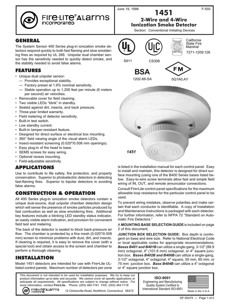
Fire-Lite 1451 User manual
