Fire-Lite MS-9600 Owner's manual

Page 1 of 5
Doc. # 51583 Rev. B 05/07/01 ECN 01-131
This Supplement has been created to inform installers about the new Signal Line Circuit (SLC) capacity
of 159 detectors and 159 modules per SLC loop; and
Introduce two new FACP software features which (1) provide a synchronized strobe programming
option, (2) allow the control panel to monitor and printout the sensitivity and drift compensation for
each addressable smoke detector connected to the system; as well as to
Provide information concerning 'Positive Alarm Sequence' and 'Printer Supervision'.
I. Synchronized Strobes
NAC Option for Synchronization
Synchronization is a panel feature that controls the activation of notification appliances in such a way that all devices will turn on
and off at exactly the same time. This is particularly critical when activating strobes which must be synchronized to conform
with a variety of regulations as well as to avoid random activation which could cause a hazardous condition. The FACP can be
programmed to operate with a variety of manufacturer's devices.
Important: When a Notification Appliance Circuit with a mix of audible and visual devices is programmed for silenceable and
the synchronization feature is selected, only the audible devices will be turned off if the Silence key is pressed. The visual
devices (strobes, etc.) will continue to operate.
Program Selection for Synchronized Strobes
1. Press the Enter or Mode key to display the following LCD readout:
2. Press 2 to display the following:
3. Enter the Master level password (default is 00000) to display the following:
4. Press down arrow key once to display the following:
Supplement to MS-9600 Manual, Rev A
Smoke Detector Capacity
Detector Sensitivity & Synchronized Strobes
Positive Alarm Sequence & Printer Supervision
Document 51583 Rev B 05/07/01 ECN 01-131
1=READ@STATUS
2=PROGRAMMING
PROGRAMMING
ENTER PASSWORD
*****
@@@@@PROGRAMMING
1=POINT@PROGRAM
2=ZONE@SETUP
3=LOOP@SETUP
@@@@PROGRAMMING
1=SYSTEM@SETUP
2=AUTOPROGRAM
3=VERIFY@LOOP

Page 2 of 5 Doc. # 51583 Rev. B 05/07/01 ECN 01-131
5. Press 1to display the following:
6. Press down arrow key once to display the following:
7. Press 2 to display the following:
8. Press 1 to program NAC 1 or press 2 to program NAC
2. The following will be displayed (the # symbol will
be replaced by 1 or 2):
9. Press 2 to display the following:
10. Press down arrow key once to display the following:
@@@@SYSTEM@SETUP
1=TROUBLE@REM@@OFF
2=BANNER
3=TIME-DATE
@@@@SYSTEM@SETUP
1=TIMERS
2=NAC
3=RELAYS
@@@@NACS
1=NAC@1
2=NAC@2
@@@@NAC@#
1=ENABLED@@@YES
2=TYPE
3=SILENCEABLE
@@@@@@@NAC@TYPE
1=BELL
2=HORN
3=STROBE
@@@@@@@NAC@TYPE
1=SYNCED@STROBE
2=AUDIBLE
3=SIREN@CIRCUIT
11. Press 1 to program the NAC as a synchronized strobe circuit.
The display will return to the following:
12. Press the down arrow key three time to display the following:
13. Press 1 to display the following:
14. Select the type of synchronized circuit according to the
manufacturer's devices installed on the NAC by pressing the
corresponding number key. Continue with the programming
of the second NAC if desired.
When all programming is completed, repeatedly press the
ESC (Escape) key to store the program information and exit
Programming mode.
@@@@NAC@#
1=ENABLED@@@YES
2=TYPE
3=SILENCEABLE
@@@@@NAC@#
1=SYNC@TYPE
@@@@@NAC@SYNC@TYPE
1=SYSTEM@SENSOR
2=WHEELOCK
3=GENTEX

Page 3 of 5
Doc. # 51583 Rev. B 05/07/01 ECN 01-131
II. Addressable Smoke Detector Sensitivity
Software Enhancement
The FACP software has been enhanced to include a feature which allows the control panel to monitor the sensitivity of each
addressable smoke detector in the system. This eliminates the need for a service person to physically connect a sensitivity test
meter to each device in the field.
Detector Data
An addressable smoke detector's ability to detect smoke can change over time as a result of component deterioration due to
environmental contaminants and dirt. Each addressable smoke detector's data (sensitivity) can be printed by entering Read Status
mode.
1. Pressing the Enter or Mode key on the control panel keypad will display the following LCD screen:
2. Press 1 to display the following:
3. Press down arrow key four times to display the following:
4. Press 3 to display the following:
5. Press 3 to print the detector sensitivity data for all addressable smoke detectors installed on the system.
Refer to the sample printout on the following page for information on interpreting the data.
Note: If a printer is not available, it is possible to use the HyperTerminal feature found in the Windows©program Accessories
folder which is resident on most personal computers. Any settings which are configured in this feature must reflect the printer
settings detailed in the FACP manual. Refer to the Windows©manual for information on the HyperTerminal feature.
1=READ@STATUS
2=PROGRAMMING
@@@@READ@STATUS
1=SYSTEM@POINT
2=ZONES
3=POWER
@@@@READ@STATUS
1=FUTURE@USE
2=PRINTER/PC
3=PRINT
@@@@@@@PRINT
1=HISTORY
2=WALKTEST@LOG
3=DETECTOR@DATA

Page 4 of 5 Doc. # 51583 Rev. B 05/07/01 ECN 01-131
DEVICE# DEVICE TYPE %DRIFT COMP. CHAMBER TIME/DATE
1D001 SMOKE (PHOTO) 20 1478 12:01AM 01-08-2001
1D002 SMOKE (PHOTO) 20 1362 12:01AM 01-08-2001
1D003 SMOKE (PHOTO) 21 1452 12:01AM 01-08-2001
1D004 SMOKE (PHOTO) 20 1350 12:01AM 01-08-2001
1D005 SMOKE (PHOTO) 21 1245 12:01AM 01-08-2001
1D006 SMOKE (PHOTO) 21 1247 12:01AM 01-08-2001
1D007 SMOKE (PHOTO) 21 1250 12:01AM 01-08-2001
Chamber Value
The Chamber Reading should be within the indicated ranges for the following smoke detectors:
• SD350(T), D350P(R) and SD300(T) Addressable Photoelectric Smoke Detectors: 405 - 2100 (obscuration of 1.00%/ft.
to 3.66%/ft.)
• CP350 and CP300 Addressable Ionization Smoke Detectors: 750 - 2100 (obscuration of 0.50%/ft. to 1.44%/ft.)
If the addressable smoke detector's Chamber reading is not within this acceptable range, clean the detector and check the
Chamber reading again. If the reading is still not within the acceptable range, immediately replace the detector.
Refer to the Fire Alarm Control Panel manual's Programming section for additional information on accessing Read Status
mode and interpreting the smoke detector addresses.
Drift Compensation
Drift compensation uses software algorithms that identify and compensate for long-term changes in the data readings from each
addressable smoke detector. These long-term changes in detector data readings are typically caused by dirt and dust accumula-
tion inside the smoke chamber. Drift compensation performs the following functions:
• Allows a smoke detector to retain its original ability to detect actual smoke and resist false alarms, even as dirt and dust
accumulate
• Reduces maintenance requirements by allowing the control panel to automatically perform the periodic sensitivity
measurements required by NFPA Standard 72
The FACP software also provides filters to remove transient noise signals, usually caused by electrical interference.
Maintenance Alert
The software determines when drift compensation for a detector reaches an unacceptable level that can compromise detector
performance. When a detector reaches an unacceptable level, the control panel indicates a maintenance alert. The following
table summarizes the three levels of maintenance alert:
A printout, similar to the following example, will be generated if an optional printer is connected to the FACP.
leveLecnanetniaMsyalpsiDsutatSPCAFsetacidnI
eulaVrebmahCwoL PERVNI rotcetedehtnimelborperawdrahA
trelAecnanetniaM 1YTRID
ehtwolebtubraensitahtnoitalumuccatsuD
leveltrelAecnanetniaMehT.timildewolla
ehterofebecnanetniamrofdeenehtsetacidni
desimorpmocsirotcetedehtfoecnamrofrep
tnegrUecnanetniaM 2YTRID timildewollaehtevobanoitalumuccatsuD
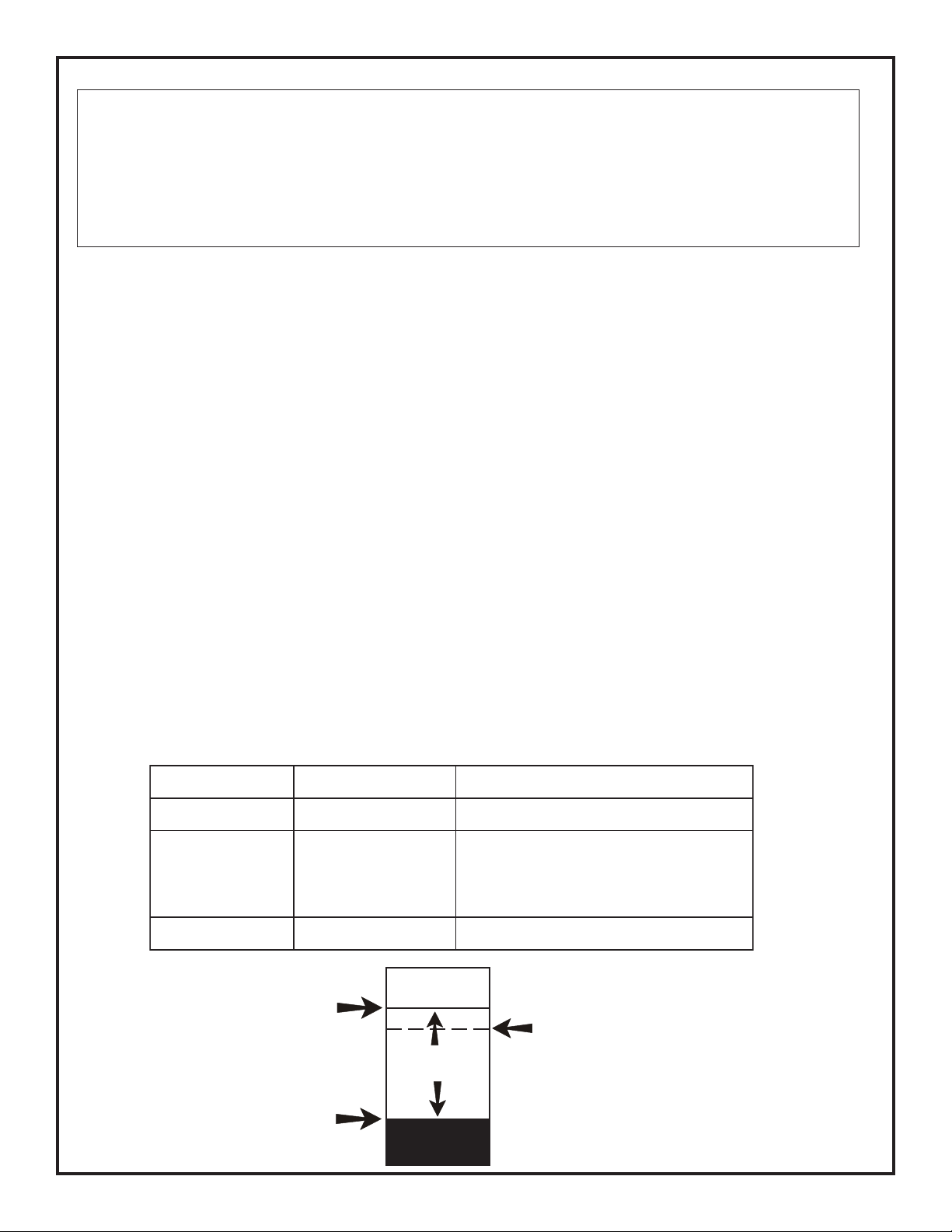
DIRTY
Acceptable
Range
LOW
VALUE
Maintenance Alert
Maintenance Urgent
Low Chamber Reading

Page 5 of 5
Doc. # 51583 Rev. B 05/07/01 ECN 01-131
The following information is provided as a clarification to the 9600 Fire Alarm Control Panel
manual.
1. PAS (Positive Alarm Sequence) programming feature. Refer to the 9600 manual page 47 and
page 114 for information on this option.
The PAS option is not available in the initial release of the 9600 software. Do not attempt to use this feature since it
is not yet functional in this product. Information on the availability of this feature will be made known on the
manufacturer's internet site along with details on how to upgrade existing software.
2. Printer Supervision. Refer to the 9600 manual page 92 for information on this option.
Printer supervision, when enabled, will typically detect the removal of the printer cable and will detect when the
printer power has been turned off. Depending upon the brand of printer, other errors such as paper empty or printer
off-line may be detected.
Other manuals for MS-9600
1
Other Fire-Lite Smoke Alarm manuals

Fire-Lite
Fire-Lite 1451 User manual

Fire-Lite
Fire-Lite MS-4012 User manual

Fire-Lite
Fire-Lite Keltron 95M3158 TTM-RPS Quick start guide

Fire-Lite
Fire-Lite D350RP Instruction Manual

Fire-Lite
Fire-Lite CP355 User manual

Fire-Lite
Fire-Lite CFP-2410B User manual

Fire-Lite
Fire-Lite AFM-16ATX User manual

Fire-Lite
Fire-Lite FACP User manual

Fire-Lite
Fire-Lite B310LP User manual
Popular Smoke Alarm manuals by other brands

System Sensor
System Sensor DH400ACDCP Installation and maintenance instructions

pdlux
pdlux PD-SO918 instructions

System Sensor
System Sensor B224RB Installation and maintenance instructions

Vision
Vision ZS 6101 IN Installation & operation manual

eTIGER
eTIGER ES-D5B manual

SharpEye
SharpEye 20/20L User and maintenance manual