Firecom F900-MB-6CO User manual

FIRECOM™, INC.
39-27 59th Street
Woodside, NY 11377
718.899.6100 TEL
718.899.1932 FAX
76647
Rev 150302
1 of 2
FIRECOM™
F900-MB-6CO
Analog Addressable
CO Sounder Base
Technology Protecting Life
®
F900-MB-6CO Analog Addressable CO Sounder Base
isdesignedtoworkinconjunctionwithfirealarmpanels
that support the Firecom approved analog addressable
protocol.
Protocol
Intelligent Combination CO Detector & Sounder Base
Integral Carbon Monoxide Detector
Integral 85dB Sounder
Six Year Field Replaceable Electrochemical CO Senor
End of Life Signaling System Indicator
Temporal 3 Sound for Smoke Detection
Temporal 4 Sound for CO Detection
Mounts on 4” Square or Octagonal Box
Low Power Consumption
Features
FIRECOMINC.COM
Analog Addressable CO Sounder Base
F900-MB-6CO
Approvals and Listings
Underwriters Laboratories
Description
The F900-MB-6CO Analog Addressable CO Sounder
Base is a combination carbon monoxide (CO) detec-
tor and sounder base. It is designed to be used as a
stand alone device or with the addition of Firecom F900
or F1000 Series analog addressable smoke, heat or
mult-sensor detectors. The CO Sounder Base is also
designedtoallowthedetectorto fitoneway only,without
snagging, with a simple clock wise twist motion. For
stand alone CO detection, two blank covers are avail-
able, the F900-MB-6COBC-LP for the low profile and
the F900-MB-6COBC-HP for the high profile.
The CO Sounder base sounds a temporal 3 sound for
smoke detection and a temporal 4 sound for carbon
monoxide detection. The integral sounder is capable
of producing an 85db tone at 10 feet. The CO Sounder
Base is powered by a UL listed Notification Appliance
Circuit,and maybesynchronized withotherCO Sounder
Bases using appropriate synchronization modules.
Each base has locking feature whereby a socket screw
oneachdetectormaybeturnedtolocateinafixing hole
in the base to prevent unauthorized removal.
The6-inch diameter F900-MB-6COAnalogAddressable
CO Sounder Base mounts to 4-inch octagonal and
4-inchsquare boxes. Whenmountingon aceiling,install
atleast4-inches from the wall. Whenmountingdetector
on the wall, install 4 to 12 inches from the ceiling.
FIRECOM™, INC.
39-27 59th Street
Woodside, NY 11377
718.899.6100 TEL
718.899.1932 FAX
76647
Rev 150302
2 of 2
Ordering Information
Model No. Part No. Description
F900-MB-6CO 76642 Analog Addressable CO Sounder Base
F900-MB-6COBC-LP 76746 Low Profile Base Cover
F900-MB-6COBC-HP 76745 High Profile Base Cover
F900-MB-6CORM 76744 CO Replacement Module
It is our intention to keep the product information up to date and accurate. We cannot cover all specific applications or anticipate all
requirements. All specifications are subject to change without notice. For more information contact: FIRECOM, INC.
Operating Voltage 24VDC
Loop Standby Current 400uA
Loop Alarm Current 3.5mA
NAC Standby Current 0mA
NAC Alarm Current 33mA
Sounder Audible Intensity 85dB at 10 feet
Electrical Specifications
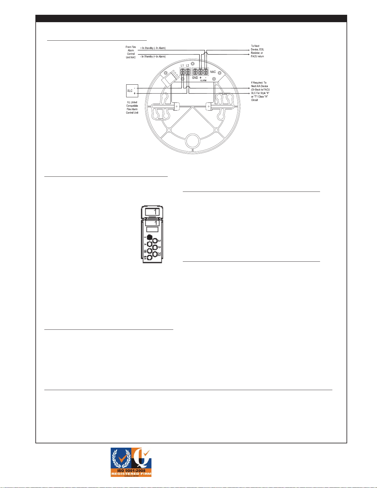
Wiring Connection
FIRECOMINC.COM
The smoke detection is addressed via the XPERT
card. The XPERT card is a plastic, coded card con-
taining seven ‘pips’.
The address is set by simply remov-
ing the ‘pips’ with a screwdriver
according to the ADDRESS DATA
chart shown on the right. The coded
card is then inserted into the side of
the base where it locks into position.
When the detector head is rotated
intothebase,theremaining‘pips’on
thecardoperate the address buttons
on the base of the detector and the
addressis read by the detector elec-
tronics. Factory set Addressable XPERT
cards are available.
The CO detection has its own address setting, which
is unique from the address of the attached smoke
detector. Set the address for the CO detection to the
CO ADDRESS DATA chart.
Address Setting
The power for the smoke detector that is mounted onto
the base and the integral Carbon Monoxide detector are
supplied by the addressable loop.
Powering the Smoke and
CO Detectors
ANotificationCircuitthat reverses voltage polarity powers
thesounder that is included intheCO Sounder Base. The
NAC circuit must be on an approved Firecom Fire Alarm
Panel. The circuit may be wired as Style 4 or Style 6.
RemotebaseoutputsfromtheCOSensorortheinstalled
Smoke Detector determine the type of sound generated
by the sounder. If the CO Sensor detects CO Levels
that indicate an Alarm condition, the sounder base will
generate a Temporal 4 sound (4 rapid beeps separated
by about 5 seconds of silence). If the attached Smoke
Detector indicates an alarm condition, the sounder base
will generate a Temporal 3 sound (three beeps separated
by about 1.5 seconds of silence).
Powering the Sounder
Popular Marine Equipment manuals by other brands

CQR
CQR EPA-NG/STD G3 Series Operating and installation instructions

Observator Instruments
Observator Instruments OMC-131 Installation and technical manual

Furuno
Furuno NX-300 Operator's manual

Humminbird
Humminbird HDR 400I Operation manual

Klaxon
Klaxon Nexus 105 DC installation instructions

Raytheon
Raytheon V700 instruction manual

VEXILAR
VEXILAR LC-8 owner's manual

CORRECT CRAFT
CORRECT CRAFT LINC PANORAY 2021 owner's manual

Teledyne
Teledyne LONGRANGER Deployment guide

Spinlock
Spinlock DECKVEST VITO 275N manual

System Sensor
System Sensor ExitPoint PF24 Installation and maintenance instructions

Lofrans
Lofrans X4 Installation and user manual


