FireplaceXtrordinair PB 24CF User manual
CoolSmart TV
PB 24CF, PB 36CF, 564 25K, 564 35K, 3615HO
(sku# 98900778)
Page 1 of 37 17602034- 12/13/21 © Travis Industries, Inc.
Compatibility
ProBuilder 24 CF 564 25K (Std. or CF)
ProBuilder 36 CF 564 35K (Std. or CF)
3615 HO Linear (sn# 3213-003633 or greater)
Packing List
(1) Convection Manifold (with grill and
mounting brackets pre-attached)
(12) Self-Drilling Tek Screws
(2) 5” Diameter Aluminum Flex Ducts
(2) Starter Collars (2) Convection Air Deflectors (Used with PB 36 ONLY)
NOTE: A power heat duct kit may also be available for this appliance. If so, you may use either the power heat
vent kit(s) or the CoolSmart TV kit, but not both. See appliance installation manual for details.
Table of Contents
Table of Contents ...................................................................................................................................................... 1
Grill and Manifold Dimensions................................................................................................................................... 2
PB 24CF & PB 36CF - Installation Overview ............................................................................................................ 3
PB 24CF & PB 36CF - Installation Requirements ................................................................................................. 4
PB 24CF - Framing the Chase............................................................................................................................... 5
PB 36CF - Framing the Chase............................................................................................................................... 6
PB 24CF & PB 36CF - Fireplace Preparation........................................................................................................ 7
PB 36CF ONLY – Convection Air Deflectors......................................................................................................... 8
PB 24CF & PB 36CF - Reduced Mantel Height .................................................................................................... 9
564 25K - Installation Overview............................................................................................................................... 10
564 25K - Installation Requirements.................................................................................................................... 11
564 25K - Framing the Chase.............................................................................................................................. 12
564 25K - Fireplace Preparation .......................................................................................................................... 13
564 25K - Reduced Mantel Height....................................................................................................................... 16
564 35K - Installation Overview............................................................................................................................... 17
564 35K - Installation Requirements.................................................................................................................... 18
564 35K - Framing the Chase.............................................................................................................................. 19
564 35K - Fireplace Preparation .......................................................................................................................... 20
564 35K - Reduced Mantel Height....................................................................................................................... 23
3615 HO - Installation Overview.............................................................................................................................. 24
3615 HO - Installation Requirements................................................................................................................... 25
3615 HO - Combustible “Over-Facing” (Optional) ............................................................................................... 26
3615 HO - Framing the Chase............................................................................................................................. 28
3615 HO - Fireplace Preparation ......................................................................................................................... 29
3615 HO – Mantel Height .................................................................................................................................... 33
CoolSmart TV Installation (36CF, 564 25K, 3615HO)............................................................................................. 34
Using oval pipe to get past an obstruction........................................................................................................... 37
Custom Valance to Disguise Outlet – (Optional) ................................................................................................. 38

CoolSmart TV
PB 24CF, PB 36CF, 564 25K, 564 35K, 3615HO
(sku# 98900778)
Page 2 of 37 17602034- 12/13/21 © Travis Industries, Inc.
Grill and Manifold Dimensions
The grill may be installed over the facing to
provide an aesthetic opening for the
convection outlet. (2) 8-32 x 1-1/2” screws
attach the trim to the upper manifold. This
allows variable thickness of finish material.
Dimensions
a b c d e
35-7/8” (912mm) 2-7/8” (74mm) 1-1/4” (32mm) 34-7/8” (886mm) 1-3/4” (45mm)
CoolSmart TV
PB 24CF, PB 36CF, 564 25K, 564 35K, 3615HO
(sku# 98900778)
Page 3 of 37 17602034- 12/13/21 © Travis Industries, Inc.
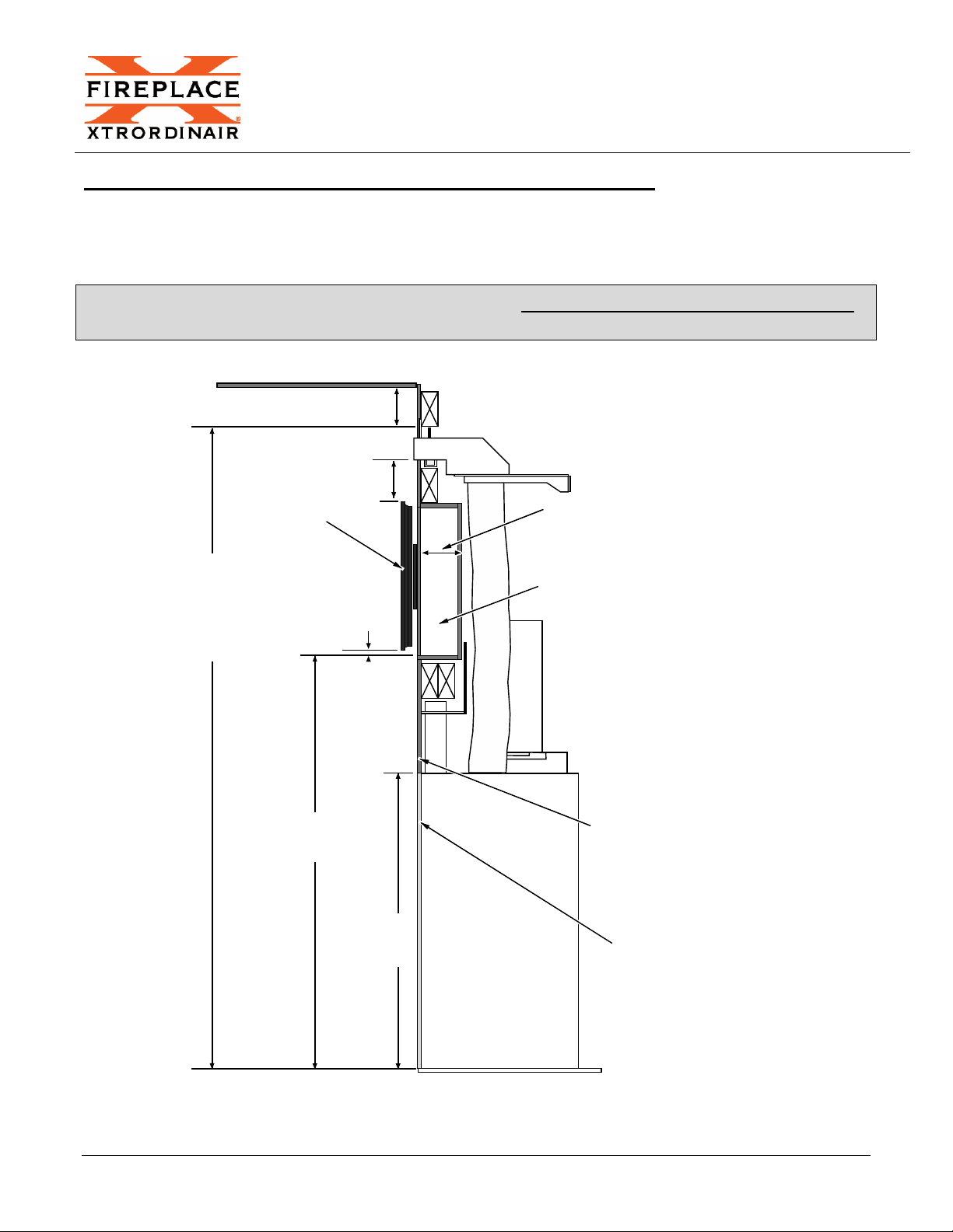
PB 24CF & PB 36CF - Installation Overview
The CoolSmart system is designed to redirect the convective heat of the fireplaces from the front of the unit, just
above the glass, to a location higher on the wall. The use of this kit allows for reduced clearances to televisions
and a recessed cavity above the fireplace. When using this kit, disregard the standard framing dimensions and
follow the framing instructions for the CoolSmart kit.
When used on the PB234 CF & PB36 CF, this kit allows for the non-combustible facing height to be reduced.
See illustration below for details.
Min. 1-1/2" (39mm)
Max. 120"
(3048mm)
Min. 73-3/4"
(1690mm)
Non-Combustible
Facing Only
C
eiling
ProBuilder
24CF & 36CF
Fireplace
Optional Recessed Pocket
Min. 35"
(889mm)
Combustible Facing
Allowed
Min. 45-1/2"
(1156mm)
Max. 3-1/2"
(89mm)
Television
Min. 1/4"
(7mm)
to the top of
the zero-clearance bo
x
Min. 1-1/4" (32mm)
CoolSmart TV
PB 24CF, PB 36CF, 564 25K, 564 35K, 3615HO
(sku# 98900778)
Page 4 of 37 17602034- 12/13/21 © Travis Industries, Inc.
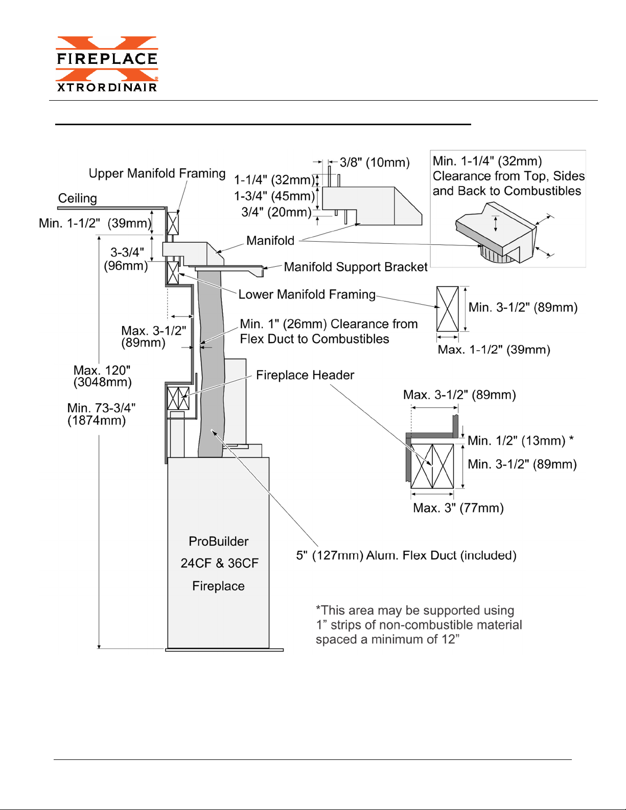
PB 24CF & PB 36CF - Installation Requirements
CoolSmart TV
PB 24CF, PB 36CF, 564 25K, 564 35K, 3615HO
(sku# 98900778)
Page 5 of 37 17602034- 12/13/21 © Travis Industries, Inc.
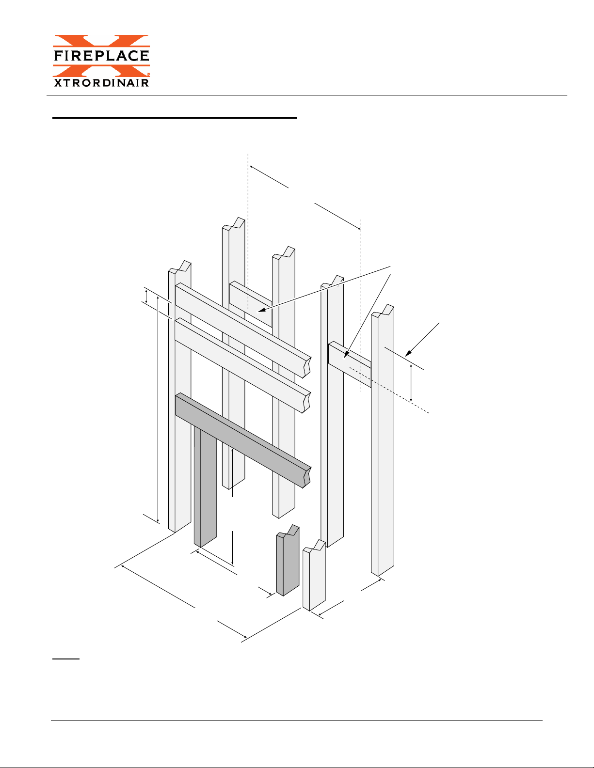
PB 24CF - Framing the Chase
When using this kit, disregard the framing dimensions in the manual and follow the framing instructions shown
below*.
NOTE: The dark-shaded framing is typically installed after the manifold is installed. It is used to secure the nailing
brackets on the fireplace to the framing. It also provides support for the facing above the fireplace. This framing
is not required in some cases (you may use other methods to secure the nailing brackets and facing).
3-3/4"
96mm
Upper Manifold Framing
Lower Manifold Framing
8-1/2"
216mm
Bottom of Upper
Manifold Framing
Braces for Manifold
Support Brackets
Max. 120"
3048mm
Min. 73-3/4"
1874mm
PB24CF
26-1/2" 674mm
15-1/2"
394mm
41-1/4"
1048mm
37-3/8" 950mm
25-1/8" 639mm
This manual suits for next models
5
Table of contents


