First Co PHYB Series Manual

*HYB *PHYB
HORIZONTAL HYDRONIC FAN COIL UNITS
Installation, Operation, and
Maintenance Instructions
W
ARNING TO
I
NSTALLER
, S
ERVICE
P
ERSONNEL
,
AND
O
WNER
Altering the product, improper installation, or replacing parts with unauthorized parts voids
all warranty or implied warranty and may result in adverse operational performance or
possible hazardous conditions to service personnel and occupants. Company employees or
contractors are not authorized to waive this warning.
NOTES: • Read the entire installation instruction manual before starting the
installation.
•
These instructions are intended as a general guide and do not supersede
national, state, or local codes in any way.
•
These instructions must be left with the property owner.
S
AFETY
C
ONSIDERATIONS
Improper installation, adjustment, alteration, service, maintenance, or use can
cause explosion, fire, electrical shock, or other conditions which may cause
personal injury or property damage. Consult a qualified licensed installer,
service agency, or your distributor for information or assistance. The qualified
licensed installer or service agency must use factory-authorized kits or
accessories when modifying this product. Refer to the individual instructions
packaged with kits or accessories when installing.
Follow all safety codes. Wear safety glasses and work gloves. Use quenching
cloth for brazing operations. Have fire extinguisher available. Read these
instructions thoroughly and follow all warnings or cautions attached to the
unit. Consult local building codes and National Electrical Code (NEC) for special
requirements.
IOM5501 Rev. A 04/22
1
General
HYB
PHYB
:
Installation, Operation, and
Maintenance
Instructions
2
Recognize safety information. This is the general safety-alert symbol .
When you see this symbol on the unit and in instruction manuals, be alert to
the potential for personal injury or damage to equipment. The lightning bolt
symbol signifies an electrical shock hazard.
WARNING:
This WARNING signifies general hazards which could result in personal
injury or death.
WARNING:
This WARNING signifies electrical shock hazards which could result in
personal injury or death.
CAUTION:
CAUTION is used to identify unsafe practices which would result in
product and property damage.
NOTE:
NOTE is used to highlight suggestions which may result in enhanced
installation, reliability, or operation.
G
ENERAL
The manufacturer does not warrant equipment subjected to abuse. Metal chips,
dust, drywall tape, paint overspray, etc. can void warranties and liability for
equipment failure, personal injury, and property damage.
The manufacturer assumes no responsibility for equipment installed in
violation of any code requirement.
WARNINGS:
•
Always wear eye protection when working on equipment.
•
Before servicing unit, always turn off all power to unit. There may be
more than one disconnect switch. Electrical shock can cause personal
injury or death.
•
When fan coil is operating, some components are operating at high
speeds. Personal injury can result from touching these items with any
object.
•
All electrical and service access panels must be secured in their proper
place before operating equipment.
•
Clear surrounding area of all tools, equipment and debris before
operating unit.
CAUTION: Unit must not be operated during building construction due to excessive
airborne dust and debris. Also, the unit must never run under any
circumstances without an air filter in place.
These instructions give information for installation of these fan coil units only.
For other related equipment, refer to the manufacturer’s instructions.
Material in this shipment has been inspected at the factory and released to the
transportation agency in good condition. When received, a visual inspection of
all cartons should be made immediately. Any evidence of rough handling or
apparent damage should be noted on the delivery receipt and the material
inspected in the presence of the carrier’s representative. If damage is found, a
claim should be filed against the carrier immediately.
All models are designed for indoor installation only. The installation of this
unit, field wiring, duct system, and other related equipment must conform to
the requirements the National Electric Code, ANSI/NFPA No. 70 (latest edition)
in the United States, as well as any state laws and local codes. Local authorities
having jurisdiction should be consulted before installation is made. Such

INSTALLATION PRECAUTIONS
HYB
PHYB:
Installation, Operation, and
Maintenance
Instructions
3
applicable regulations take precedence over the general instructions contained
in this manual.
INSTALLATION PRECAUTIONS
WARNING: Some units are very heavy. Use two or more people when moving and
installing these units. Failure to do so could result in personal injury or
death. Contact with metal edges and corners while applying excessive
force can result in personal injury. Use gloves when handling equipment.
Use caution during installation or while servicing equipment.
Installation of this fan coil should be performed only by a licensed contractor to
ensure proper installation and the safety of the installer. Observe the following
precautions for typical installations:
•
Always use proper tools and equipment.
•
No wiring or other work should be attempted without first ensuring fan coil
is completely disconnected from the power source and locked out. Always
verify that a good permanent, uninterrupted ground connection exists
prior to energizing any power sources.
•
Always review the nameplate and wiring diagram on each unit for proper
voltage and control configurations. This information is determined from the
components and wiring of the unit and may vary from unit to unit.
•
When soldering or brazing to the unit, it is recommended to have a fire
extinguisher readily available. When soldering close to water valves or other
components, heat shields or wet rags are required to prevent damage.
•
When the fan coil unit is in operation components are rotating at high
speeds.
•
Units must be installed level or angled toward the drain nipple to ensure
proper drainage and operation.
•
Check unit prior to operation to ensure that the condensate water will drain
toward the drain connection. An overflow drain or an auxiliary drain pan
under the fan coil may be required as a back up to a clogged primary drain.
•
Be sure that the drain pan is free from foreign material prior to start up.
•
Check filter media installation to ensure that it is installed correctly. Use the
directional arrows or other information on the filter to determine the proper
flow direction.
•
Ensure air distribution system does not exceed the external static rating of
the unit.

FAN COIL UNIT
HYB
PHYB
:
Installation, Operation, and
Maintenance
Instructions
4
FAN COIL UNIT
The installer must adhere strictly to all local and national code requirements
pertaining to the installation of this equipment. These units are designed for
installation in a horizontal position. All units are designed for indoor use only,
and are agency listed for installation with zero clearance to combustible
materials. This includes the fan coil cabinet, discharge plenum and connecting
ducts.
Free return installation of HYB unit (non-ducted return air): The furred down
area must be completely sealed (except return air grille) to ensure that all
return air is pulled from the conditioned space and not from other areas of the
building structure.
Access must be provided for servicing the unit. If this access is provided by a
removable ceiling panel, ample space must be allowed for removal of the
blower panels and to provide access to electrical and plumbing controls.
When required, the unit can be tilted toward the drain nipple to ensure proper
drainage.
NOTES: • A field-fabricated secondary drain pan, with a drain pipe routed to the
outside of the building, may be required in installations over a finished
living space or in any area that may be damaged by water overflow from
the main drain pan. In some localities local codes may require a secondary
drain pan for any horizontal installation.
•
If a condensate overflow shut off switch, that is designed to be installed in
the drain line, is used in place of a secondary drain line then place it in the
primary drain line between the fan coil and the P-trap.
MOUNTING
It is important to ensure fan coils are securely mounted and the structure is
sufficient to support the weight of the equipment. All anchors for mounting
equipment must be placed and sized to ensure a safe and durable installation.
These units are provided with four (4) mounting slots. Metal washers and nuts
of the proper size are to be provided by the installer. When necessary, use
shims to obtain the proper level to ensure condensate will drain from the unit.
If mounting to wooden joists, use as a minimum 1/4-inch x 2-inch wood screws
fully engaged with fender washers for securing this unit to the structure.
AIR DISTRIBUTION DUCTS
All duct work must be installed in accordance with National Fire Protection
Association Codes 90A and 90B. Ducts should be adequately insulated to
prevent condensation during the cooling cycle and to minimize heat loss
during the heating cycle. All return air must be filtered to prevent dirt buildup
on the coil surface. If there is no ducted return, applicable installation codes
may limit the unit to installation only in a single story residence. In many cases
it is acceptable to use ducting of the same size as the fan coil connections.
However, unique arrangements or long duct runs must be confirmed by a local
professional. The manufacturer will not be responsible for misapplied
equipment.
Supply and return duct system must be adequately sized to meet the system’s
air requirements and static pressure capabilities. The duct system should be
insulated with a minimum of 1-inch insulation with a vapor barrier in
conditioned areas or 2-inches, minimum, in unconditioned areas.

ELECTRICAL
HYB
PHYB:
Installation, Operation, and
Maintenance
Instructions
5
ELECTRICAL
WARNINGS:
Electric Shock Hazard
•
Disconnect all power supplies before servicing; lock out/tag out to
prevent accidental electrical shock. Note: there may be multiple power
sources.
•
Use copper conductors only.
•
Install all parts and panels before operating.
•
Failure to follow these warnings can result in injury or death.
All wiring must comply with local and national code requirements. Units are
provided with wiring diagrams and nameplate data to provide information
required for necessary field wiring.
These units may be provided with a Class 2 transformer for 24-volt control
circuits. Should any add-on equipment also have a Class 2 transformer
furnished, care must be taken to prevent interconnecting outputs of the two
transformers by using a thermostat with isolating contacts.
PIPING
PIPING
PRECAUTIONS
1.
Flush all field piping prior to connection to remove all debris.
2.
Use wet cotton rags to cool valve bodies when soldering.
3.
Open all valves (mid-way for hand valves, manually open on motorized
valves) prior to soldering.
4.
When soldering to bronze or brass, heat the piping while in the socket/cup
and begin introducing the solder when the flux boils rapidly. Avoid direct
flame into the solder joint.
5.
Heat can only be applied to the cup of the valve body for a minimal time
before damage occurs (even with the use of wet rags).
6.
Avoid rapid quenching of solder joints as this will produce joints of inferior
quality.
7.
The valve package will not support the weight of the connecting pipes. All
pipes connected to the units must be completely supported prior to
connection to the unit.
8.
Provisions must be made for expansion and contraction of piping systems.
All horizontal and vertical risers, including runouts, must be able to
withstand significant movement with temperature changes. Failure to do so
will result in damage and failure of piping, fittings and valves throughout
the building.
9.
Never insulate the heads or motorized portion of control valves. Damage can
occur in the form of excessive heat build up and interference to the
operation and moving parts will result.
10.
All piping made in the field should be installed with consideration of
additional space for any electrical routing that may be required.
11.
Connect all piping per accepted industry standards and observe all
regulations governing installation of piping systems.
CAUTION: Hydronic systems are not designed to hold pressurized air and should
only be tested with water. Pressurizing system with air could damage
equipment.
12.
When all connections are complete, pressure test system. Repair any solder
joint leaks and gently tighten any leaking valve packing nuts and piping
accessories, as required.

PIPING
HYB
PHYB
:
Installation, Operation, and
Maintenance
Instructions
6
PIPING
INSTALLATION
These units employ a hydronic coil designed for use with either hot or chilled
water.
•
All piping must be adequately sized to meet the design water flow
requirements as specified for the specific installation. Piping must be
installed in accordance with all applicable codes.
•
The piping connections on the equipment are not necessarily indicative of
the proper supply and return line sizes. To minimize restrictions, piping
design should be kept as simple as possible.
CAUTIONS:
•
When connecting piping to fan coil units, do not bend or reposition the
coil header tubing for alignment purposes. This could cause a tubing
fracture resulting in a water leak when pressure is applied to the system.
•
Prior to connecting to the fan coil all external piping must be purged of
debris.
•
All chilled water piping must be insulated to prevent property damage
from condensation.
Condensate drain lines must be installed with adequate slope away from the
unit to assure positive drainage. In cases where the HYB unit is installed in a
cabinet or enclosure and the drain pan is located on the suction side of the
blower, a negative pressure exists at the drain pan. HBY units installed in this
manner require a minimum trap of 1-1/2 inches provided in the drain line to
assure proper drainage. HYB and PHYB fan coil units may be located where the
return air space is large enough that a negative pressure is not present,
however, a trapped condensate line is recommended in case a negative
condition should occur, the unit would drain properly.
PIPING INSULATION
Installing Contractor - After the system has been proven leak free, all lines
and valve control packages must be insulated to prevent condensate drippage
or insulated, as specified on the building plans.
NOTE: Many valve packages will not physically allow all components to fit over an
auxiliary drain pan. It is the installers responsibility to insulate all piping to
ensure adequate condensation prevention.
DUCTWORK
All duct work must be installed in accordance with industry accepted practices,
and all applicable national and local code requirements.
NOISE
These fan coil units are designed for quiet operation, however, all air
conditioning equipment will transfer some amount of noise to the conditioned
space. This should be taken into consideration when planning the location of
the equipment.
PIPING
HYB
PHYB:
Installation, Operation, and
Maintenance
Instructions
7
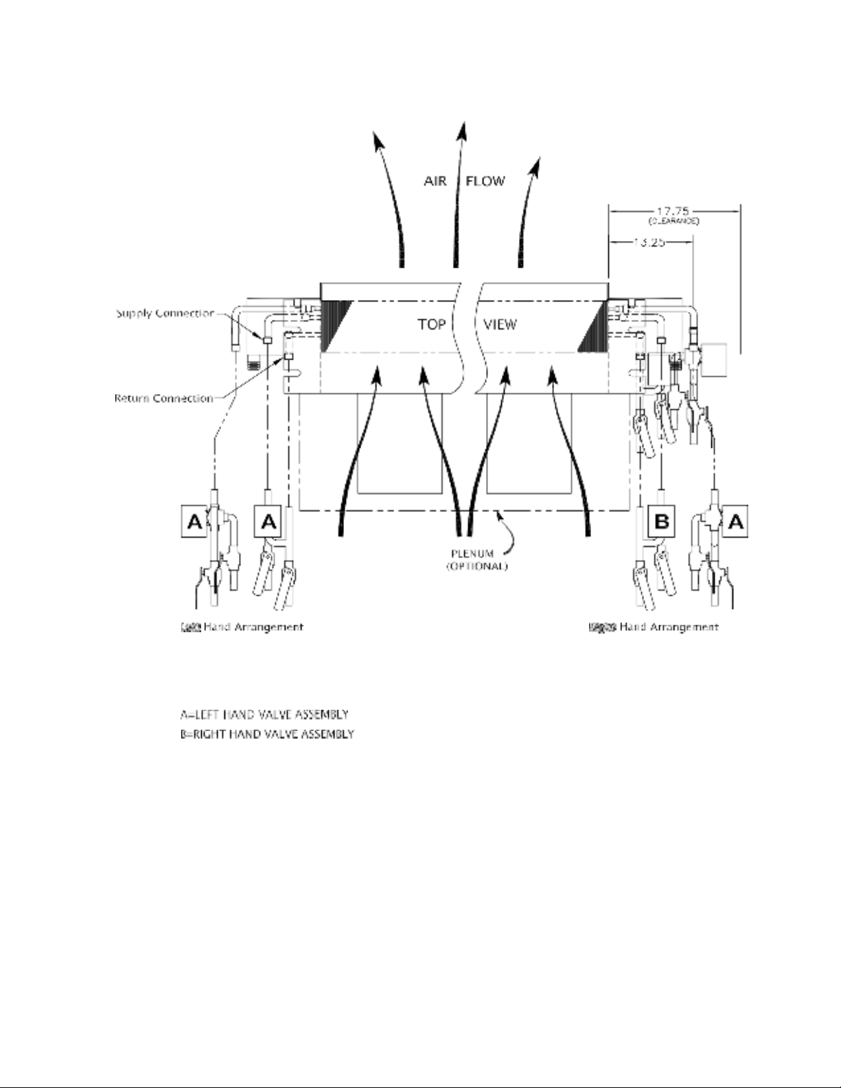
FIGURE 1. Determination of Right-Hand/Left-Hand References
Installation of Valve Cluster Assemblies
HYB
PHYB
:
Installation, Operation, and
Maintenance
Instructions
8
I
NSTALLATION OF
V
ALVE
C
LUSTER
A
SSEMBLIES
Horizontal hydronic fan coil units may use either a two-way (Figure 2) or three-
way (Figure 3) motorized valve assembly. The following procedures describe
each installation.
P
ROCEDURE
1: T
WO
-W
AY
M
OTORIZED
V
ALVE
A
SSEMBLIES
1.
The two-way motorized valve assembly should be attached to the supply
header which is the connection nearest the air outlet flange on the unit.
2.
Prior to soldering the joints, operate all the hand valves to ensure that the
handles will fully open and close without interference to other valves,
ceiling, wall, plenum or other accessories.
3.
All valves will operate at any angle with the exception of the motorized
valve, which must never be installed with the power head below horizontal.
The actuator box requires a 3/4-inch clearance for removal.
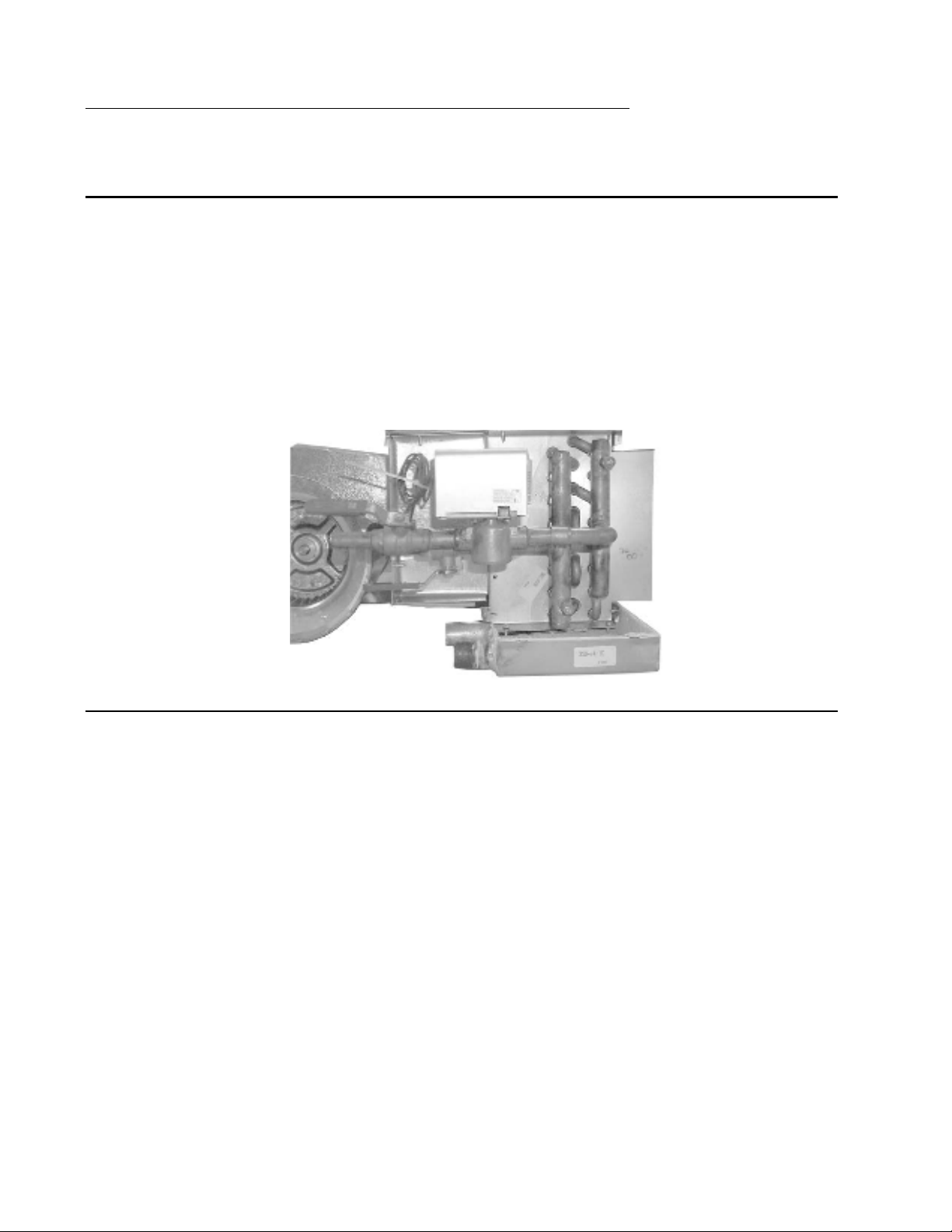
FIGURE 2. Two-Way Motorized Valve Assembly
P
ROCEDURE
2: T
HREE
-W
AY
M
OTORIZED
V
ALVE
A
SSEMBLY
1.
The three-way valve assemblies will mount to the coil in only one position.
On four-pipe right hand systems a “B” valve assembly is required for the
chilled water connection and a “A” valve assembly is required for the hot
water connection. On left hand systems a “A” valve assembly is required for
the chilled water connection and the hot water connection. (See Figure 1.)
2.
Prior to soldering the joints, operate all the hand valves to ensure that the
handles will fully open and close without interference to other valves,
ceiling, wall, plenum or other accessories.
3.
All valves will operate at any angle with the exception of the motorized
valve, which must never be installed with the power head below horizontal.
The actuator box requires a 3/4-inch clearance for removal.

PRE-STARTUP CHECKS
HYB
PHYB:
Installation, Operation, and
Maintenance
Instructions
9
FIGURE 3. Three-Way Motorized Valve Assembly
PRE-STARTUP CHECKS
WARNINGS:
•
Electrically ground fan coil. Connect ground wire to ground terminal
marked “GND”. Failure to do so can result in injury or death.
•
Do not touch any rotating component with any object. Damage to the
equipment and personal injury can occur.
CAUTION: Any device such as a fan switch or thermostat that has been furnished by the
factory for field installation must be wired in strict accordance with the wiring
diagram that is supplied with the unit. Failure to do so could result in damage
to components and will void all warranties.
Prior to starting the unit:
1.
Ensure supply voltage matches nameplate data.
2.
Ensure unit is properly grounded.
3.
With power off, check blower wheel set-screws for tightness and ensure
blower wheels rotate freely and quietly.
4.
Ensure fan coil is properly and securely installed.
5.
Ensure unit is sloped toward drain line.
6.
Ensure unit will be accessible for servicing.
7.
Ensure condensate line is properly sized, run, trapped, pitched and tested.
8.
Ensure all cabinet openings and wiring connections have been sealed.
9.
Ensure a clean filter is in place and of adequate size.
10.
Ensure all access panels are in place and secured.
11.
Check that coil(s), valves and piping have been leak checked and insulated
as required.
12.
Ensure that all air has been vented from the system.

MAINTENANCE
HYB
PHYB
:
Installation, Operation, and
Maintenance
Instructions
10
MAINTENANCE
INSPECTION AND
CLEANING
Before start-up all of the components should be given a thorough check.
Optimal operation of this equipment requires cleanliness. Often after
installation of this equipment additional construction activities occur. Care
must be taken to protect the equipment from debris during these construction
phases.
FAN
The fan should be inspected and cleaned annually, in conjunction with
maintenance of the motor and bearings. It is important to keep the wheels
clean in order to avoid imbalance and vibration.
MOTOR
Check motor connections to ensure that they are secure and made in
accordance with the wiring diagram.
The blower motor should be cleaned annually, and if it has oiling ports, it should be
oiled with a good grade of SAE 20 oil. Normally a few drops of oil in each bearing is
sufficient.
WARNING:
Units with ECM motors have line voltage power applied at all times. Make
sure power is disconnected before servicing.
FILTER
The air filter should be cleaned or replaced every 30 days or more frequently if
severe conditions exist. Always replace the filter with the same type as
originally furnished.
COIL
Any dust or other contaminants which accumulate on the heat transfer surfaces
interferes with the air flow and impairs heat transfer. The coil must be kept
clean by any of the following methods.
•
Cleaning with low-pressure compressed air.
•
Flushing or rinsing with water (a detergent is advisable for greasy surfaces).
•
Prior to the water system start-up and balancing, the chilled/hot water
systems should be flushed to clean out dirt and debris construction. All unit
service valves are closed during this process. Strainers are to be installed in
the piping mains to prevent this material from entering the units during
normal operation.
CAUTION: Be sure to return valves to their proper operating positions prior to start-up.
DRAIN PIPING
The drain should always be:
•
Connected or piped to an acceptable disposal point sloped away from the
unit at least 1/8-inch per foot.
•
Checked before summer operation.
•
Periodically checked during summer operation.
NOTE: A trap may be required per local codes and for odor containment.
PREVENTATIVE
MAINTENANCE
To achieve maximum performance and service life of each piece of equipment,
a formal schedule of regular maintenance should be established and
maintained.

MAINTENANCE
HYB
PHYB:
Installation, Operation, and
Maintenance
Instructions
11
MAINTENANCE
UPDATES
Contact factory for Maintenance Program information.
P.O. BOX 270969, Dallas, TX 75227
www.firstco.com or www.ae-air.com
The manufacturer works to continually improve its products. It reserves the right to change design and specifications without notice.
©2022 First Co., Applied Environmental Air
This manual suits for next models
1
Table of contents
Popular Air Conditioner manuals by other brands

Retro Aire
Retro Aire R30C Installation, operation & maintenance manual

Mitsubishi Electric
Mitsubishi Electric MSZ-LN18VG2W operating instructions

Mitsubishi Electric
Mitsubishi Electric MSZ-GE25VA operating instructions

Frigidaire
Frigidaire CRA073PU11 use & care

Daikin
Daikin Split Sensira R32 Service manual

Panasonic
Panasonic CS-E9CKP operating instructions


