First International Computer AN11 User manual

AN11
MAINBOARD
MANUAL
DOC No.: M00B04
Rev. : A0
Date : 11, 2001
Part No. : 25-11607-20

Handling Precautions
Warning:
1. Static electricity may cause damage to the integrated circuits on
the motherboard. Before handling any motherboard outside of its
protective packaging, ensure that there is no static electric charge
in your body.
2. There is a danger of explosion if the battery is incorrectly
replaced. Replace only with the same or an equivalent type
recommended by the manufacturer.
3. Discard used batteries according to the manufacturer’s
instructions.
4. Never run the processor without the heatsink properly and firmly
attached. PERMANENT DAMAGE WILL RESULT!
Observe the following basic precautions when handling the motherboard
or other computer components:
nWear a static wrist strap which fits around your wrist and is
connected to a natural earth ground.
nTouch a grounded or anti-static surface or a metal fixture such as a
water pipe.
nAvoid contacting the components on add-on cards, motherboards,
and modules with the golden fingers connectors plugged into the
expansion slot. It is best to handle system components by their
monting brackets.
The above methods prevent static build-up and cause it to be discharged
properly.
Trademark
All trademarks mentioned in this manual are registered properly of
the respective owners.
Handling Precautions
This manual may not, in whole or in part, be photocopied, reproduced,
transcribed, translated, or transmitted in whatever form without the
written consent of the manufacturer, except for copies retained by the
purchaser for personal archival purposes.
Notice

i
TableofContents
Table of Contents
Chapter 1 Overview
Package Checklist .......................................................................... 1-2
The AN11 Mainboard ............................................................... 1-3
Main Features ................................................................................ 1-4
FIC Unique Innovation for Users (NOVUS) -
Enhanced Mainboard Features and System Support .................... 1-6
Chapter 2 Installation Procedures
Quick Reference (from Page 2-2 to 2-5) .......................................... 2-2
Mainboard Layout .................................................................... 2-2
1). Clear CMOS, FSB Speed Select,
Auto Detect CPU Core Voltage .................................... 2-3
2). Front Panel Block Cable Connection ............................ 2-5
3). CPU Fan Installation .................................................... 2-5
1). Set System Jumpers/Switches ................................................... 2-5
Clear CMOS: CLR_CMOS ................................................. 2-5
FSB Speed Select: FS ........................................................ 2-6
None Over Clock Enable: JP1_4G ...................................... 2-6
Auto Detect CPU Core Voltage: ADV_EN ......................... 2-7
CPU Core Voltage Setting: ADV ........................................ 2-7
Optional RAID Function Enable: RAID_JP ...................... 2-8
2). Install Memory Modules .......................................................... 2-8
3). Install the CPU .......................................................................... 2-9
4). Install Expansion Cards ............................................................. 2-10
5). Connect Devices ....................................................................... 2-11
Floppy Diskette Drive Connector ..................................... 2-11
IDE Device Connectors ..................................................... 2-12
ATX Power Connectors .................................................... 2-12
Quick Reference (German) G-1
Quick Reference (French) F-1
Quick Reference (Spanish) S-1
Quick Reference (Japanese) J-1
Quick Reference (Chinese) C-1
Quick Reference (Simplified Chinese) |||||||||||||SC-1

ii
AN11MainboardManual
Fan Connectors ................................................................. 2-13
Wake-On-Ring Connector ................................................. 2-13
Wake-On-Lan Connector .................................................. 2-14
Blue Tooth Audio Port Connector .................................... 2-14
CD Audio-In Connectors .................................................. 2-15
Front Panel Block, Power LED and Speaker Connector .... 2-15
PS/2 Keyboard and Mouse Connector ............................. 2-17
Universal Serial Bus Connectors ....................................... 2-17
Printer Connector .............................................................. 2-18
Serial Port Connectors ....................................................... 2-18
Audio I/O Jacks ................................................................ 2-19
Game/MIDI Connector ...................................................... 2-19
Chapter 3 BIOS Setup
CMOS Setup Utility ....................................................................... 3-1
Standard CMOS Setup ................................................................... 3-2
Advanced BIOS Features .............................................................. 3-4
Advanced Chipset Features .......................................................... 3-7
Integrated Peripherals .................................................................... 3-10
Power Management Setup ............................................................. 3-16
PnP/PCI Configurations ................................................................. 3-20
PC Health Status ............................................................................ 3-22
Frequency/Voltage Control ............................................................ 3-23
Load Fail-Safe Defaults .................................................................. 3-23
Load Optimized Defaults ................................................................ 3-24
Supervisor/User Password ............................................................ 3-24
Save and Exit Setup ....................................................................... 3-24
Exit without Saving ........................................................................ 3-24

1 - 1
Overview
Overview
Chapter 1
The new Socket-A 1stMainboard®AN11Ôis an ATX sized motherboard
supporting the latest generation of AMD AthlonÔand DuronÔprocessors
at industry leading speeds. By utilizing DDR ( Double Data Rate ) transfer rate
the 100/133 MHz AMD Athlon system bus effectively reaches Front Side Bus
speeds of 200/266 MHz. The board allows 3 PC2100/PC1600 DDR DIMMs for
up to 3 GB of DDR SDRAM.
The AN11 is based around the high performance V-link VIA KT266AÔchipset
comprised of VIA VT 8366A system controller for the North Bridge and the
VIA VT8233Ô for the South Bridge. The AGP 4X functions supported by
KT266A®provides the end-user a photo-realistic 3D experience suitable for
the most robust 3D games and software environments. Onboard AC97 sound,
embedded in VT8233, ensures high quality audio.
The mainboard also comes equipped with the new NOVUS®range of innova-
tive features that assist in the installation and maintenance. The features in-
clude Easy Key, which provides instant keyboard access to the BIOS for
adjustments to Clock and Default settings and LogoGenie, which allows you
to create your own customized logo to be displayed during system boot up.
The BIOS Guardian is an Anti Virus utility that prevents viruses from damag-
ing your system BIOS and rendering your system inoperative.
Expansion is provided by 1 AGP(2X/4X), and 6 PCI slots. In addition, the
1stMainboard AN11 is equipped with 2 dual channeled enhanced PCI bus
master IDE connectors, plus two optional IDE RAID connectors for support-
ing more efficient data backup. Standard I/O connections include 2 serial ports,
1 parallel port, 1 PS/2 mouse and keyboard connector, 4 USB connection ports,
1 IR port, and 1 media connector (Line-In, Line-Out, Mic-In, game port).

1 - 2
AN11MainboardManual
Package Checklist
If you discover any item below was damaged or lost, please contact your
vendor.
þThe mainboard þThis user manual
þOneFDDcable þOne HDD cable
þOneATA/100cable þ Two software CDs (CD Pro, CD Plus)
þOneUSB dual cable
IMPORTANT:AMDCPU HEATSINKINSTALLATION
Be ware finish heat sink install. Before you boot system, please
check the heat sink is complete contact with die of CPU.
The poor contact will bring about over heat, it may damage your
processor.
Itisstrongly recommendedthatat leasta250-watt ATXpowerpupply
be used for this motherboard. Make sure that your ATX power sup-
ply can supply at least 20 amperes on teh +5-Volt lead and 10mA
on the +5-Volt standby lead (+5VSB). Your system may become
unstable / unreliable and may experience difficulty in powering up if
your power supply is inadequate.
NOTE: CD Pro that contains patch files, onboard video/audio chip
drivers, related online help and other useful information can be
found in your mainboard package.
Please install it right after your Windows operating system installa-
tion is done.
Place your CDPro in the drive, an operating menu will
appears in your monitor. Please select
Auto Installation
. It will auto-
matically detect which software tools (patch files, drivers) that the
mainboard needs. Press OK button to go through the whole instal-
lation procedure in a very straight forward and easy way. It also
provides you with a custom way to select wanted patch files and
software drivers that for onboard chips use. The top menu of the
CD Pro lists all the functions that allowed by this board.

1 - 3
Overview
The AN11 Mainboard

1 - 4
AN11MainboardManual
Main Features
nEasy Installation
||BIOS with support for Plug and Play, auto detection of IDE hard drives,
||LS-120|drives, IDE ZIP drives, Windows 98SE, Windows ME, Windows
||NT, Windows 2000, Windows XP, and OS/2.
■Leading Edge Chipset
VIA VT8366A is a single-chip North Bridge for Socket A based Athlon
CPUs with 200/266 MHz Front Side Bus with AGP 4X and PCI plus ad-
vanced memory controller that supports PC1600/PC2100 DDR SDRAM.
VIA VT8233 is a highly Vlink client highly integrated controller that sup-
ports PC99-compliant system. The VT8233 also supports ATA 100 stan-
dard.
■Versatile Main Memory Support
Accepts up to 3 GB DRAM using three DDR DIMMs from 256 MB to 3
GB with support for lightenning-fast (PC1600/PC2100) DDR SDRAM .
■Enhanced PCI Bus Master IDE Controller with Ultra DMA 33/66/100
Support
Integrated Enhanced PCI Bus Master IDE controller features two dual-
channel connectors that up to four Enhanced IDE devices, including CD-
ROM and Tape Backup Drives, as well as Hard Disk Drives supporting
the new Ultra DMA 100 protocol. Standard PIO Mode 3, PIO Mode 4,
DMA Mode 2, DMA Mode 4, UltraDMA-100 Mode 5 devices are also
supported.
■AMD Processors Support
Athlon Socket 462 CPU: 800 MHz to 1.4 GHz and up*at 200 MHz FSB/
1.0 to 1.4 GHz at 266 MHz FSB;
Duron Socket 462: 800 to 950 MHz at 200 MHz FSB.
Athlon XP: 1.5 to 1.9 GHz and up*
Morgen 1 to 1.2 GHz and up*
(*: not tested yet)

1 - 5
Overview
■AGP, ACR, and PCI Expansion Slots
One AGP Bus and one ACR (Advanced Communication Riser) expansion
slot and five PCI Bus expansion slots provided the room to install a full
range of add-on cards.
■Compact Onboard Audio Subsystem
Embeded in VIA VT8233, an integrated high bandwidth Vlink client con-
troller, direct sound AC97 audio subsystem. UltraDMA-66/100 master
mode EIDE controller, six USB controller, ACPI enhanced power manage-
ment, and PC99 compliant.
■■
■■
■Super Multi Input/Output (I/O) Support
Integrated Plug and Play multi-I/O chipset features two high-speed UART
16550 compatible serial ports, one EPP/ECP capable parallel port, one IR
port, one game port, and one FDD connector.
nConvenient Rear Panel USB Connection Support
Two USB ports integrated in the rear I/O panel and two extra USB ports
for either front or rear panel connection allow convenient and high-speed
Plug and Play connections to the growing number of USB compliant
peripheral devices on the market.
■Optional IDE RAID Level 0/1 Support
The optional feature allows this board to back up huge amount data in a
more efficient way.
nOnboard Accelerated Graphics Port (AGP)
The motherboard is installed one 32-bit 1.5V AGP 2X/4X bus with a
dedicated 66MHz/133MHz path from the graphics card to the system
memory offering much greater bandwidth than the 32-bit PCI bus does.
AGP enabled 3D graphics cards can directly access main memory across
this fast path instead of using local memory.

1 - 6
AN11MainboardManual
■■
■■
■BIOS Guardian
BIOS Guardian by default is enabled. It must be disabled in order to
reflash BIOS, thus effectively acts as a fire-wall against viruses that can
attack the BIOS while the system is running.
WARNING: While excute Step3 below, please do not turn off the
sytsem power in order to avoid BIOS damage.
BIOS Guardian can be disabled as follows:
1. Go to BIOS Set Up Menu. (Press Del key while booting.)
2. Go to Advanced BIOS Features Set Up Submenu.
3. Disable BIOS Guardian.
4. Save the setting, and restart system.
FIC Unique Innovation for Users (NOVUS) -
Enhanced Mainboard Features and System Support
■■
■■
■LogoGenie
A user friendly GUI supporting Windows 95/98/98SE (not Windows 2000/
NT/ME), LogoGenie allows you to customize, create or select a Logo
which will be displayed when the system is booting.
NOTE:
1. LogoGenie supports Award BIOS only.
2. If you create a Logo file (.bmp) by LogoGenie, the file size must
||||be 640 x 464 x 256 colors.
To enable this utility, please proceed as follows:
1. Insert CD Pro (version number). Select LogoGenie from the Menu
and follow the installation instructions.
2. After LogoGenie has been installed, go to Windows Start Box.
In Programs Menu, select LogoGenie 2.0, then select LogoGenie.
3. Press F1 to read Help file to understand how to use this software if
it is new to you.

1 - 7
Overview
■■
■■
■Easy Key
Instead of completing the multi-layered BIOS setup process these 3 Easy
Key functions provide direct access to Sub-Menus when completing
BIOS settings adjustments.
Easy-Keys are as follows:
Ctrl + c: To enter clock settings menu.
Ctrl + p: To load Performance Default settings and restart.
Ctrl + f: To load Fail-Safe Default settings and restart.
NOTE: However, if it is disabled and while boot the system, the
POST screen will be held and shows you the message to let you
know the current status of BIOS Guardian. To press G key will en-
able the BIOS Guardian again; or simply to press the space bar
will continue the booting process.
■■
■■
■Overclock Partner
Should the system not start because clock speed settings have been
increased to a speed incompatible with the system, the Overclock Partner
allows you to reboot at system default settings, protecting hardware from
any damages.
Complete the following steps:
1. Turn the system off.
2. Restart while holding down the Insert key. It is important that the
Insert key is held down until the default clock speed is shown on
the POST screen.
3. Enter BIOS settings menu, and re-set clock speed desired or default.

1 - 8
AN11MainboardManual
This Page Left Blank for Note

2 - 1
Installation Procedures
Chapter 2
Installation Procedures
The mainboard has several user-adjustable jumpers on the board that allow you to
configure your system to suit your requirements. This chapter contains information
on the various jumper settings on your mainboard.
To set up your computer, you must complete the following steps:
■ Step 1 - Set system jumpers/switches
■ Step 2 - Install memory modules
■ Step 3 - Install the Central Processing Unit (CPU)
■ Step 4 - Install expansion cards
■ Step 5 - Connect ribbon cables, cabinet wires, and power supply
■ Step 6 - Set up BIOS software
■ Step 7 - Install supporting software tools
WARNING: Excessive torque may damage the mainboard. When
using an electric screwdriver on the mainboard, make sure that
the torque is set to the allowable range of 5.0 ~ 8.0kg/cm.
Mainboard components contain very delicate Integrated Circuit
(IC) chips. To prevent static electricity from harming any of the
mainboard sensitive components, you should follow the follow-
ing precautions whenever working on the computer:
1. Unplug the computer when working on the inside.
2. Hold components by the edges and try not to touch the IC
||||chips, leads, or circuitry.
3. Wear an anti-static wrist strap which fits around the wrist.
4. Place components on a grounded anti-static pad or on the bag
that came with the component whenever the components are
separated from the system.
2 - 2
AN11MainboardManual
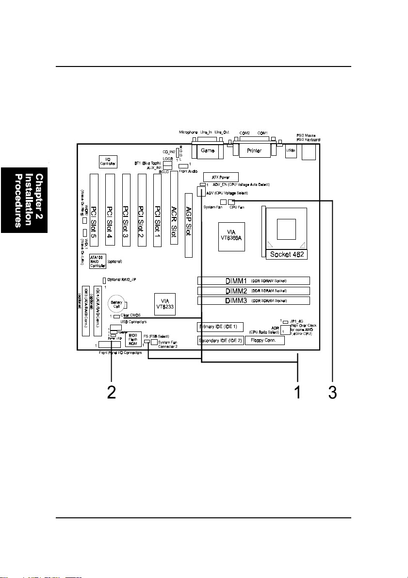
Mainboard Layout
Quick Reference (from Page 2-2 to 2-5)

2 - 3
Installation Procedures
1). Clear CMOS, FSB Speed Select,
Auto Detect CPU Core Voltage

2 - 4
AN11MainboardManual
NOTE: Please set the jumper ADV_EN at Disable before you adjust
theswitchADV.
2). Front Panel Block Cable Connection

2 - 5
Installation Procedures
1). Set System Jumpers/Switches
NOTE: Users are not encouraged to change the jumper settings
not listed in this manual. Changing the jumper settings improperly
may adversely affect system performance.
3). CPU Fan Installation
This connector is linked to the CPU fan. Without sufficient air circulation, the
CPU may overheat resulting in damage to both the CPU and the mainboard.
Damage may occur to the mainboard and/or the CPU fan if these pins are
used incorrectly. These are not jumpers, do not place jumper caps over these
pins.
Clear CMOS: CLR_CMOS
The CMOS RAM is powered by the onboard button cell battery. To clear the
RTC data: (1) Turn off your computer. (2) Place the jumper cap onto the pinpair
1-2 to clear CMOS. (3) Turn on your computer until CMOS checksum error
appears. (4) Turn off your computer. (5) Take off the jumper cap to disable it.
(6) Turn on your computer. (7) Hold down the Delete key when boots. (8) Enter
the BIOS Setup to re-enter user preferences.

2 - 6
AN11MainboardManual
None Over Clock Enable: JP1_4G
The jumper allows you to stop the over ratio clock function if you install an
AMD CPU that is ratio-unlocked and over 1.4GHz (1.4GHz inclued).
Once this jumper set at ON, the functions of ADV will not work.
FSB Speed Select: FS
The jumper allows users to select the front side bus speed.

2 - 7
Installation Procedures
Auto Detect CPU Core Voltage: ADV_EN
The 3-pin jumper allows you to start the over voltage driving capability of this
mainboard by disabling this jumper and set the switch ADV according to the
table below to approach the best performance.
WARNING: Voltage and frequency above CPU original specifica-
tions are not guaranteed to be stable.
CPU Core Voltage Setting: ADV
The switch allows you to set the CPU core voltage to approach the best
performance according to the table below after you set the jumper ADV at
Disable.

2 - 8
AN11MainboardManual
2). Install Memory Modules
1. Locate the DIMM slots on the mainboard.
2. Install the DIMM straight down into the DIMM slot using both hands.
3. The clip on both ends of the DIMM slot will close up to hold the DIMM
in place when the DIMM reaches the slot bottom.
Press the clips with both hands to remove the DIMM.
Optional RAID Function Enable: RAID_JP
The 3-pin jumper allows you to enable optional RAID features.
Table of contents
Other First International Computer Motherboard manuals

Popular Motherboard manuals by other brands


Lite-on Tech
Lite-on Tech NA115 user manual

ECS
ECS Motherboard user manual

Silicon Laboratories
Silicon Laboratories Si5380 user guide

Texas Instruments
Texas Instruments SoundPlus INA1651EVM user guide

NXP Semiconductors
NXP Semiconductors MIMXRT1060-EVKB quick start guide

Texas Instruments
Texas Instruments DS100BR410EVK-4 user guide


