Lite-on Tech NA115 User manual

NA115
Intel® 845 Motherboard
USER’S MANUAL
Intel® Pentium®4 Willamette/Northwood Processor Motherboard
Rev. 1.0

NA115 Motherboard
Revision History
Revision Date Description
1.0 Initial release of NA115 motherboard user’s manual
Item Checklist
1 NA115 Motherboard
1 Floppy Cable
1 ATA Cable 66/100
1 I/O Shield
1 Heatsink Retention Module
1 CD for Motherboard Driver
NA115 User Manual
Quick Installation Guide
Intel® Pentium® 4 Willamette/Northwood are registered trademark of Intel Corporation.
Copyright © 2001, Lite-On Tech./ System BU

NA115 Motherboard
Safety Instructions
Please follow some precautions when operating your computer.
1. Always unplug the power cord when inserting any add-on card or module inside the system.
2. Use a grounded wrist strap before handling computer components. If one is not available, touch both of your
your hands to a safely grounded object or to a metal object.
3. Place components on a level grounded antistatic pad or on the packaging that came with the components
whenever the components are separated from the system.
4. Keep equipment away from moisture and humidity.
5. Keep this User’s Manual for future reference.

NA115 Motherboard
Table of Contents
Chapter 1. Introduction …………………………………………………………………… 1
Motherboard Specification …………………………………………………………………………. 1
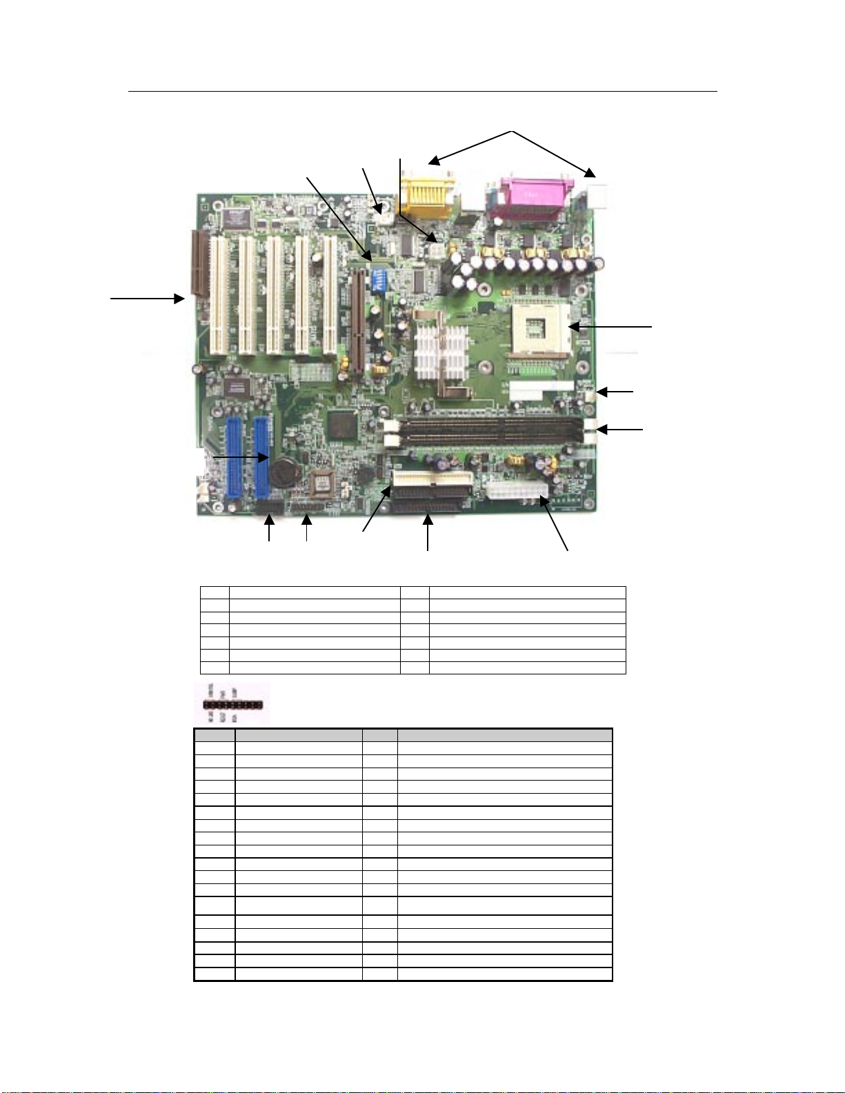
NR115 Motherboard Layout …………………………………………………………………….…. 3
Chapter 2. Hardware Installation Process ………………………………………..4
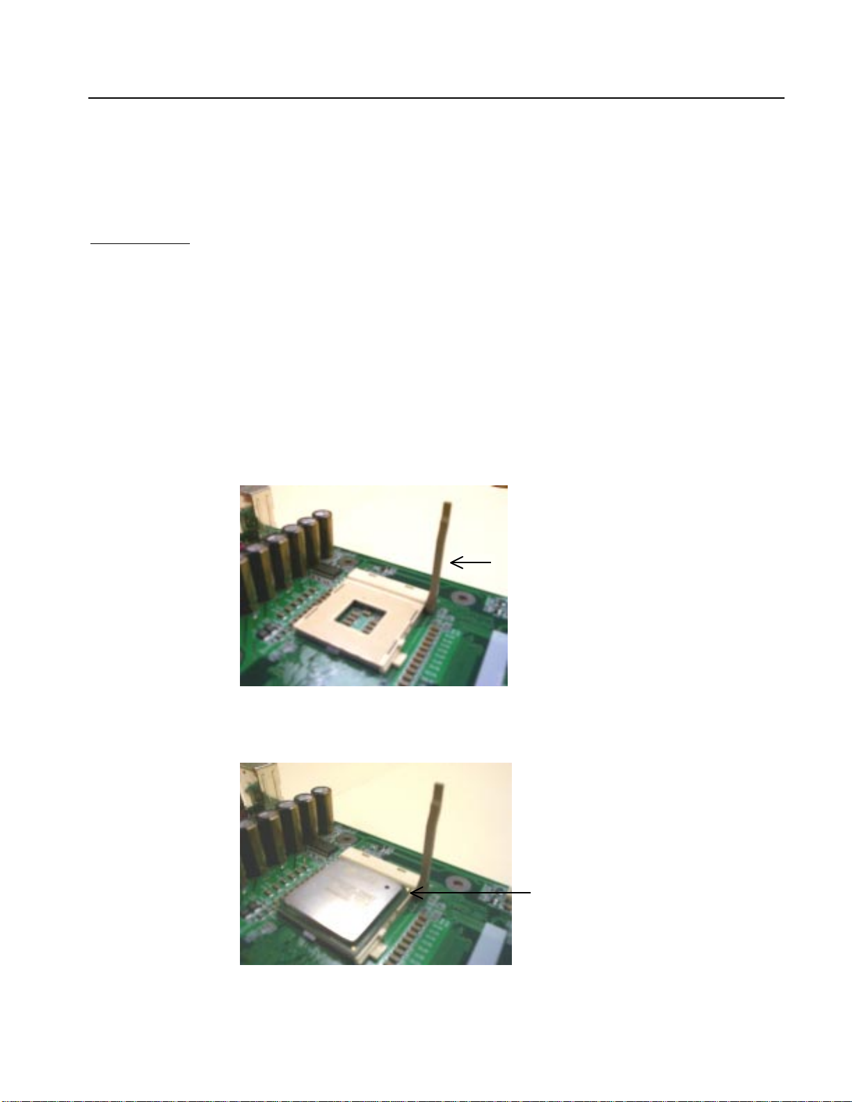
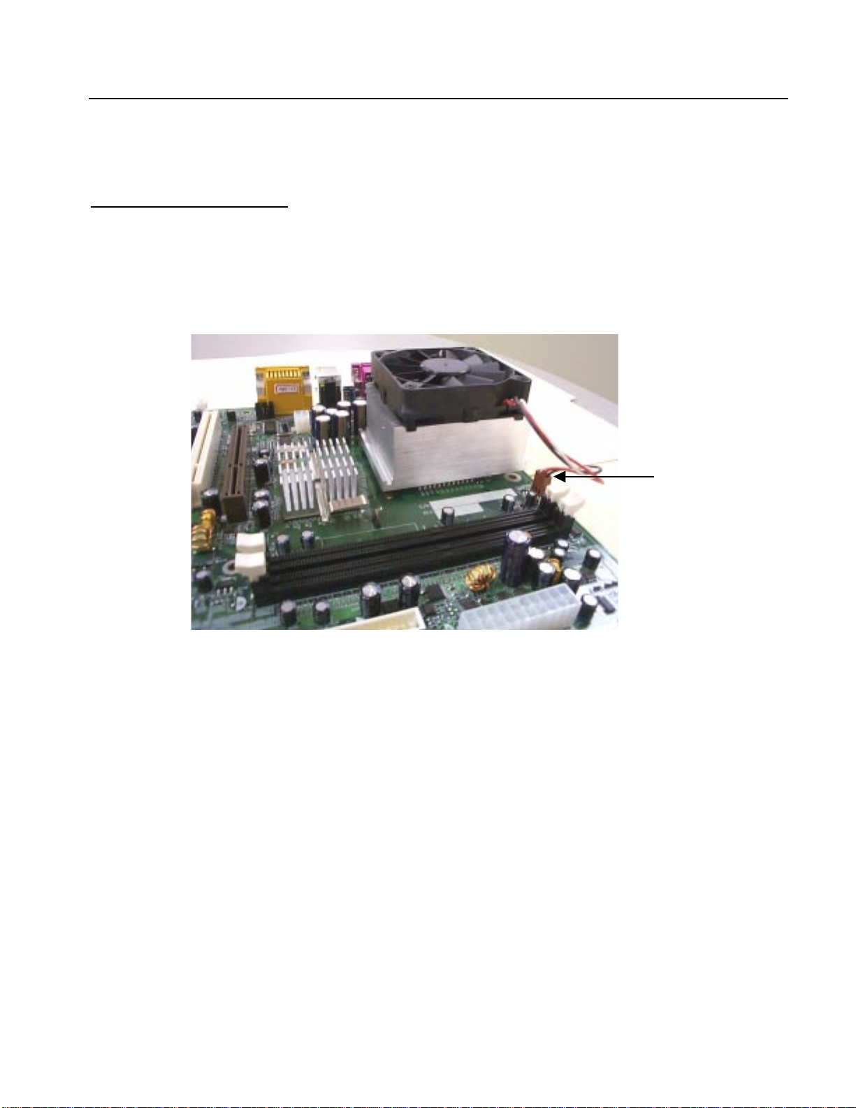
Installing Central Process Unit (CPU) ……………………………………………………………..4
Installing Memory Modules ………………………………………………………………………… 6
Connecting IDE and Floppy Disk Cables and Drives ……………………………………………7
Installing Expansion Cards ………………………………………………………………………… 9
Connect Power Supply Cable ……………………………………………………………………. 10
I/O Back Panel Introduction ………………………………………………………………………. 11
Jumpers Introduction ……………………………………………………………………………… 13
Chapter 3. AMI® BIOS Setup ………………………………………………………….. 17
Entering Setup ……………………………………………………………………………………... 17
The Main Menu ……………………………………………………………………………………. 17
Standard CMOS Setup …………………………………………………………………………… 18
Advanced CMOS Setup ……………………….…………………………………………………. 19
Advanced Chipset Setup ………………………………………………………………………. 20
Power Management Setup ……………………………………………………………………….. 21
PCI/Plug and Play Setup …………………………………………………………………………. 22
Peripheral Setup …………………………………………………………………………………… 23
Hardware Monitor Setup ………………………………………………………………………….. 24
Auto-Detect Hard Disks …………………………………………………………………………… 25
Change User Password …………………………………………………………………………... 26
Change Supervisor Password ……………………………………………………………………. 27
Auto Configuration with Optimal Settings ……………………………………………………….. 28
Auto Configuration with Fail Safe Settings ……………………………………………………… 29
Save Settings and Exit ……………………………………………………………………………. 30
Exit Without Saving ………………………………………………………………………………... 31

NA115 Motherboard
1
Chapter 1 Introduction
Motherboard Specifications
Form Factor:
• ATX Form Factor
• Size 12” x 9.6” (30.5cm x 24.4cm)
Processor:
• Socket mPGA478B
• Intel® Pentium® 4 Willamette/Northwood.
System Memory:
• 2 DIMM Sockets support up to 2GB.
• Support PC200/PC266 (PC1600/ PC2100) DDR SDRAM.
Core Logic Chipset:
• Intel® GMCH 82845 (Graphics and Memory Controller Hub).
• Intel® ICH2 82801BA (I/O Controller Hub).
PCI bus:
• PCI 2.2 compliant
Audio/Video:
• 3D audio compliant with AC’97 revision 2.1 specification.
• ADI AD1885 CODEC.
• External 1.5V AGP slot. AGP 2.0 compliant.
BIOS:
• 2Mbit flash EEPROM
• AMI® BIOS, PnP, ACPI, SMBIOS 2.3, Boot Block, DMI
___________________________________________________________________________

NA115 Motherboard
2
IDE Ports:
• Promise PDC20265R ATA-100 RAID controller
• 4 IDE ports support up to 8 devices
• Support Ultra DMA 33/66/100
On Board I/O:
• ATX power connector.
• +12V power connector.
• Aux power connector (option).
• Floppy connector.
• Front panel connector (Switch, LED, IRDA).
• Header to support two USB ports at front side.
• Header for front side LINE-OUT and MIC-IN (option).
• 3 Fan headers for CPU, chassis and system.
• ATAPI headers (CD IN, AUX IN).
• Header for chassis intrusion (option)
• Header for MONO-OUT (option)
Additional Features:
• Hardware monitor capability.
• Keyboard/Mouse/USB wake up function.
• Supports S1, S3, S4 and S5 ACPI states.
Expansion Slots:
• 1 AGP slot.
• 5 PCI slots.
• 1 CNR slot shared with one PCI slot.

NA115 Motherboard
3
NA115 Motherboard Layout
A CPU Socket H Front Side USB
B CPU Fan Socket I ATA-100 Raid IDE Connector
C Memory Sockets J Expansion Slots
D Power Supply Connector K Audio Connector
E Floppy Connector L Back Panel Connectors
F IDE Connectors M Front Side Bus Frequency Selector
G Front Panel Connector
Front Panel Connector Pin Definition
Pin Signal Name I/O Description
1 HD_PWR O Hard Disk LED pull-up to VCC
2 HDR_BLNK_GRN O Front panel Green LED signal
3 HDA* O Hard Disk Active LED signal
4 HDR_BLNK_YEL O Front panel Yellow LED signal
5 GND - Ground
6 FPBUT_IN I Front panel On/Off button signal
7 FP_RESET* I Front panel Reset button signal
8 GND - Ground
9 VCC O
10 FPSLP* I Front panel sleep button signal
11 IRRX I IRDA serial input
12 GND - Ground
13 GND - Ground
14 KEY - KEY
15 IRTX O IRDA serial output
16 VCC O
17 NC - not connected
18 NC - not connected
A
B
C
D
D
E
F
G
J
M
L
I
H
K

NA115 Motherboard
4
Chapter 2 Hardware Installation Process
Installing the Central Process Unit (CPU)
CPU Installation
1. Unlock the CPU socket by pulling the lever up to a 90-degree angle.
2. Position the CPU above the socket such that the marked corner (pin1) matches the corner near the base
of the lever.
3. Place the CPU into the socket. If the CPU is unable to insert properly, check its orientation and attempt
to re-install.
Warning! Do not force the CPU into the socket. Doing so will prompt bending of the pins and create
damage to the CPU.
4. Close the socket by lowering the lever and locking the lever in place.
Step 1
90 degree angle
Step 2
Pin1

NA115 Motherboard
5
Installing the Central Process Unit (CPU)
cont.
CPU Heat Sink Installation
1. Read the related CPU heat sink user’s manual for more detailed installation procedures.
2. Connect CPU fan power cable into the CPU fan connector on the motherboard.
CPU Fan Connector

NA115 Motherboard
6
Installing Memory Modules
1. Push the white retaining clips on each of the memory socket outwards.
2. Match the notches on the contact edge of the memory module to the ridges in the memory socket.
3. Insert the memory module vertically into place. When properly inserted, the white retaining clips will
move inward to lock in the module.
4. Repeat installation process when adding additional modules.
Total Memory Sizes With Unbuffered DDR DIMM
Devices used on DIMM 1 DIMMx64/x72 2 DIMMsx64/x72
64 Mbit (2Mx8x4 banks) 128 MBytes 256 MBytes
64 Mbit (1Mx16x4 banks) 64 MBytes 128 MBytes
128 Mbit (4Mx8x4 banks) 256 MBytes 512 MBytes
128 Mbit (2Mx16x4 banks) 128 MBytes 256 MBytes
256 Mbit (8Mx8x4 banks) 512 MBytes 1 GByte
256 Mbit (4Mx16x4 banks) 256 MBytes 512 MBytes
512 Mbit (16Mx8x4 banks) 1 GByte 2 GBytes
512 Mbit (8Mx16x4 banks) 512 MBytes 1 GByte
Retaining Clip

NA115 Motherboard
7
Connecting IDE and Floppy Disk Cables
1. Connecting the floppy disk ribbon cable into the motherboard. The side of the cable with the red
stripe needs to be inserted into the Pin1 side of the floppy disk connector.
2. Connecting the IDE ribbon cable into the motherboard. The side of the cable with the red stripe
should be inserted into Pin1 side of the IDE connector.
IDE Connectors
Red Stripe
to Pin1
Floppy Connector
Red Stripe
to Pin1

NA115 Motherboard
8
Connect Floppy and IDE Drives
NOTE: If installing two IDE devices on the same ribbon cable, one device is to be set as “master” and the
second as “slave”. Please refer to IDE device manuals for master and slave settings.
1. Mount the desired drives into the case.
2. Connect the floppy disk ribbon cable and power cable into the device.
3. Connect the IDE ribbon cable and power cable into the device.
Power Cable
Floppy Disk Drive
Floppy Disk Ribbon Cable
Hard Disk Drive
Power Cable
IDE Ribbon Cable

NA115 Motherboard
9
Installing Expansion Cards
1. Read the related expansion card’s installation instructions before inserting the expansion card into the
motherboard.
2. Remove the slot covers from the chassis case where the expansion cards will be placed.
3. Press the expansion card firmly into the expansion slot of the motherboard.
4. Secure the card with the screw provided.
5. Repeat same procedure when adding additional expansion cards.

NA115 Motherboard
10
Connect the Power Supply Cables
NOTE: The ATX power connector is keyed for proper insertion.
1. Place the plastic clip of the power connector over the plastic tab on the motherboard power connector.
The plastic clip should lock into the plastic tab.
Power Supply Connector

NA115 Motherboard
11
I/O Back Panel Introduction
(1) PS/2 Keyboard and PS/2 Mouse Connector
This connector supports standard PS/2 keyboard and PS/2 mouse.
(2) Parallel Port and Serial Ports (COM1/COM2)
This connector supports 2 standard COM ports and 1 Parallel port.
Devices (i.e. printer) can be connected into the Parallel port.
Devices (i.e. mouse and modem etc. can be connected into the Serial ports.
1
2
3
4
PS/2 Mouse Connector (6 pin Female)
PS/2 Keyboard Connector (6 pin Female)
Parallel Port (25 pin Female)
COM 1 COM 2
Serial Ports (9 pin Male)
5

NA115 Motherboard
12
I/O Back Panel Introduction
cont….
(3) USB Connector
Before connecting device(s) into the USB connections, determine if devices have a standard interface.
Make sure your computer Operating System (OS) supports the USB controller. If not, contact your OS
or device(s) vendors for more information.
(4) Game Port
This connector supports joystick, MIDI keyboard and other related audio devices.
(5) Audio Connectors
Once onboard audio driver has been installed, the speakers may be connected into the Line out jack,
audio devices such as CD-ROM etc., and a microphone into the MIC in jack.
USB 1
USB 2
Line out Line In MIC in

NA115 Motherboard
13
Jumper Introduction
Jumper Settings
The following graphic shows the meaning of the jumper with cover and without cover.
PIN 1 PIN 1
OFF ON (1-2)
FWH Lock
This jumper allows you to set FWH lock.
Reference: JP2
Connector Type: 1 x 3
JP2 Description Jumper Placement
1-2
FWH Lock Put the jumper cover on pin1 and pin2.
2-3
FWH Unlock (Default) Put the jumper cover on pin2 and pin3.
BIOS Configuration
This jumper allows you to set CPU speed.
Reference: JP3
Connector Type: 1 x 3
JP3 Description Jumper Placement
1-2
Normal Mode (Default) Put the jumper cover on pin1 and pin2.
2-3
BIOS Conf. (save speed) Put the jumper cover on pin2 and pin3.
OPEN
BIOS Recovery Remove jumper from JP5.

NA115 Motherboard
14
Jumper Introduction
cont.
Clear CMOS (Optional)
This jumper allows you to clear the content of the CMOS.
Reference: JP1
Connector Type: 1 x 3
JP1 Description Jumper Placement
1-2
Normal Put the jumper cover on pin1 and pin2.
2-3
Clear content of CMOS Put the jumper cover on pin2 and pin3.
Clear Password
This jumper allows you to clear the password of the BIOS.
Reference: JP4
Connector Type: 1 x 3
JP4 Description Jumper Placement
1-2
Normal (Default) Put the jumper cover on pin1 and pin2.
2-3
Clear BIOS password Put the jumper cover on pin2 and pin3.

NA115 Motherboard
15
Jumper Introduction
cont.
The following table shows the Front Side Bus Frequency Selector settings.
Front Side Bus Frequency Selector
FSB SELECT SEL1 SEL2 SEL3 SEL4 SEL5 SEL6
AUTO OFF OFF OFF OFF OFF OFF
100MHZ ON OFF ON OFF OFF OFF
102MHZ ON ON ON ON ON ON
105MHZ ON OFF ON ON ON ON
108MHZ ON ON OFF ON ON ON
111MHZ ON OFF OFF ON ON ON
114MHZ ON ON ON OFF ON ON
117MHZ ON OFF ON OFF ON ON
120MHZ ON ON OFF OFF ON ON
123MHZ ON OFF OFF OFF ON ON
126MHZ ON ON ON ON OFF ON
130MHZ ON OFF ON ON OFF ON
133MHZ ON OFF OFF OFF OFF OFF
136MHZ ON ON OFF ON OFF ON
140MHZ ON OFF OFF ON OFF ON
144MHZ ON ON ON OFF OFF ON
148MHZ ON OFF ON OFF OFF ON
152MHZ ON ON OFF OFF OFF ON
156MHZ ON OFF OFF OFF OFF ON
160MHZ ON ON ON ON ON OFF
164MHZ ON OFF ON ON ON OFF
166MHZ ON ON OFF ON ON OFF
170MHZ ON OFF OFF ON ON OFF
175MHZ ON ON ON OFF ON OFF
180MHZ ON OFF ON OFF ON OFF
185MHZ ON ON OFF OFF ON OFF
190MHZ ON OFF OFF OFF ON OFF
200MHZ ON ON OFF OFF OFF OFF

NA115 Motherboard
16
Jumper Settings
cont.
The following table shows the Front Side USB Connector Pin Definition.
J37
Front Side USB Connector Pin Definition
Pin Signal Name Description
1 V2+ Front Side USB Port2 VCC
2 V1+ Front Side USB Port1 VCC
3 USB2+ Front Side USB Port2
Signal+
4 USB1+ Front Side USB Port1
Signal+
5 USB2- Front Side USB Port2
Signal-
6 USB1- Front Side USB Port1
Signal-
7 GND2 Front Side USB Port2 GND
8 GND1 Front Side USB Port1 GND
9 NC No Connect
10 USBOC USB Over-Current Detect
USB1+
V1+V2+
USB2+
USB2- USB1-
GND2 GND1
NC USBOC
Table of contents
Other Lite-on Tech Motherboard manuals

Lite-on Tech
Lite-on Tech NA280 User manual

Lite-on Tech
Lite-on Tech NA120 User manual

Lite-on Tech
Lite-on Tech TR100 User manual

Lite-on Tech
Lite-on Tech Scenic Edition X101 User manual

Lite-on Tech
Lite-on Tech NR120 User manual

Lite-on Tech
Lite-on Tech NA380 User manual

Lite-on Tech
Lite-on Tech TR101 User manual
Popular Motherboard manuals by other brands

Linear Technology
Linear Technology DC708 quick start guide

IEI Technology
IEI Technology IMBA-C2060 user manual

MSI
MSI H67MA-E45 series user manual

Analog Devices
Analog Devices EagleEye EVAL-ADSW4000KTZ user guide

Gigabyte
Gigabyte GA-Z270P-D3 user manual

Intel
Intel BLKD945PSNLK Technical product specification