Fischione 1010 ION MILL User manual

MODEL 1010 ION MILL
Standard Magnification Version
INSTRUCTION MANUAL
E.A. Fischione Instruments, Inc.
9003 Corporate Circle
Export, PA 15632 USA
Phone (724)325-5444
FAX (724)325-5443
www.fischione.com
PN 009-0988 Rev.3

Contents
Model 1010 Ion Mill – Standard Magnification Version
Contents
SAFETY 1
BACKGROUND 2
Ion Milling Theory 2
Model 1010 Features 2
Ion Sources 3
Basic Procedure for Sample Preparation and Ion Milling 3
SYSTEM OVERVIEW 4
Sample Chamber 5
Vacuum System 6
Gas Flow 7
Water Flow 7
Sample Cooling Capability (Optional) 7
Endpoint Detection Capability (Optional) 7
Visual Monitoring 8
Control System and Software 8
Specifications 8
INSTALLATION AND SETUP 9
Warnings, Cautions, and Notes 9
Assessing initial condition 9
Unpacking and Inspecting 9
Accessories 10
Connections 11
Process gas 11
Exhaust gas 12
Water 12
Microscope Installation 12
Process Control Computer 13
Laser Installation (optional) 14
Power Connections 14
For US application 14
For non-US application 14
To change operating voltage 15
OPERATION 16
Basic Startup Procedure 16
Dewar Bakeout 17
Laser Calibration 18
Loading TEM Specimens 19
Specimen Cooling (optional) 20
Ion Milling 21
Insert specimen 22
Microscope 22
Endpoint determination (optional) 22
Set milling parameters 22
Set data logging options 24
Save recipe 24
Start milling 25
View Data 27
Basic Shutdown Procedure 29
MAINTENANCE 30

Contents
Model 1010 Ion Mill – Standard Magnification Version
Preventive Maintenance Schedule 30
Cleaning the Air Filters 30
Changing the Fuses 31
Opening the Enclosure 32
Enclosure removal 32
Window Cleaning 33
Front access door window 33
Bottom light window 34
Cleaning o-rings 36
Lamp Replacement 36
Ion Source Maintenance 38
Disconnect gas line 39
Remove ion source cartridge 39
Remove cathode 41
Remove anode and extractor 41
Inspect components 42
Clean components 43
Service ion source body components 43
Ultrasonically clean and inspect components 45
Reassemble ion sources 45
Verify electrical connections 45
Replace ion source 46
Attach gas and electrical connections 46
Check leaks 46
Start up ion source 47
Ion Source Alignment 47
Adjust source alignment 47
Verify alignment 48
Dewar Maintenance 48
Remove Dewar 48
Change Zeolite® desiccant 51
Install Dewar 52
Evacuate Dewar wall space 52
Chamber and Specimen Stage Cleaning 52
Stage maintenance 52
Ion source flange 56
Pirani gauge tube 58
Bottom plate 59
Mass Flow Controllers 60
Verify electronics 60
Evaluate flow 61
Replace mass flow controller 61
Leak Detection 62
High pressure 62
Vacuum 63
Turbomolecular Vacuum Pump 64
Reinstall Enclosure 64
Back Panel 64
TROUBLESHOOTING 65
Diagnosis chart 65
Error messages 67
Laser 68
SPARE PARTS AND CONSUMABLES 69
REFERENCES 71

Contents
Model 1010 Ion Mill – Standard Magnification Version

Safety
1 Model 1010 Ion Mill
Standard Magnification Version
Safety
The following hazards are associated with the Model 1010 Ion Mill.
ELECTRICAL HAZARD. High voltages can cause severe injury or death. Do not
connect the power cord until after the initial inspection and after making gas connections.
Do not attempt to operate the instrument with the cover removed.
Before disconnecting the power cord from the instrument, wait one minute to ensure that
any charged electronic component will discharge.
HAZARDOUS MATERIALS. Toxic, reactive, or radioactive materials can cause
severe injury or death. If hazardous materials will be inserted into the Model 1010 for
processing, the ion mill must be connected directly to an exhaust system capable of
accommodating the hazardous material. If radioactive materials will be milled, the
instrument must be enclosed in protective shielding.
LASER HAZARD. Laser beams can cause severe eye damage. Do not point the laser
beam into your eye or into any other person’s eye. The ion mill contains a 670 nm red
(visible) Class II laser.
COMPRESSED GAS. High-pressure gas stream can injure exposed skin or eyes. Point
tubing away from personnel while connecting or disconnecting gas cylinders.
MECHANICAL HAZARD. Moving parts can injure fingers and hands. Do not attempt
to operate the instrument with the cover open.

Background
2 Model 1010 Ion Mill
Standard Magnification Version
Background
For many of today's advanced materials, ion milling is an excellent preparation technique
for specimens that require TEM analysis. Electron microscopy needs samples that are
clean, representative of the bulk state, and free of physical or chemical artifacts. To
prepare them for microscopy, samples are first mechanically sectioned and ground and
then polished or milled to remove additional material.
Electropolishing requires that a sample material possess a certain level of electrical
conductivity.
Ion milling is effective for all materials, including those that are relatively nonconductive
such as semiconductors and insulators as well as those that are conductive (metallic or
semimetallic). Ion mills bombard the substrate surface with an energetic ion beam.
E.A. Fischione’s Model 1010 Ion Mill is a state-of-the-art, compact, tabletop precision
ion milling/polishing system that consistently produces high-quality TEM specimens
with large electron transparent areas.
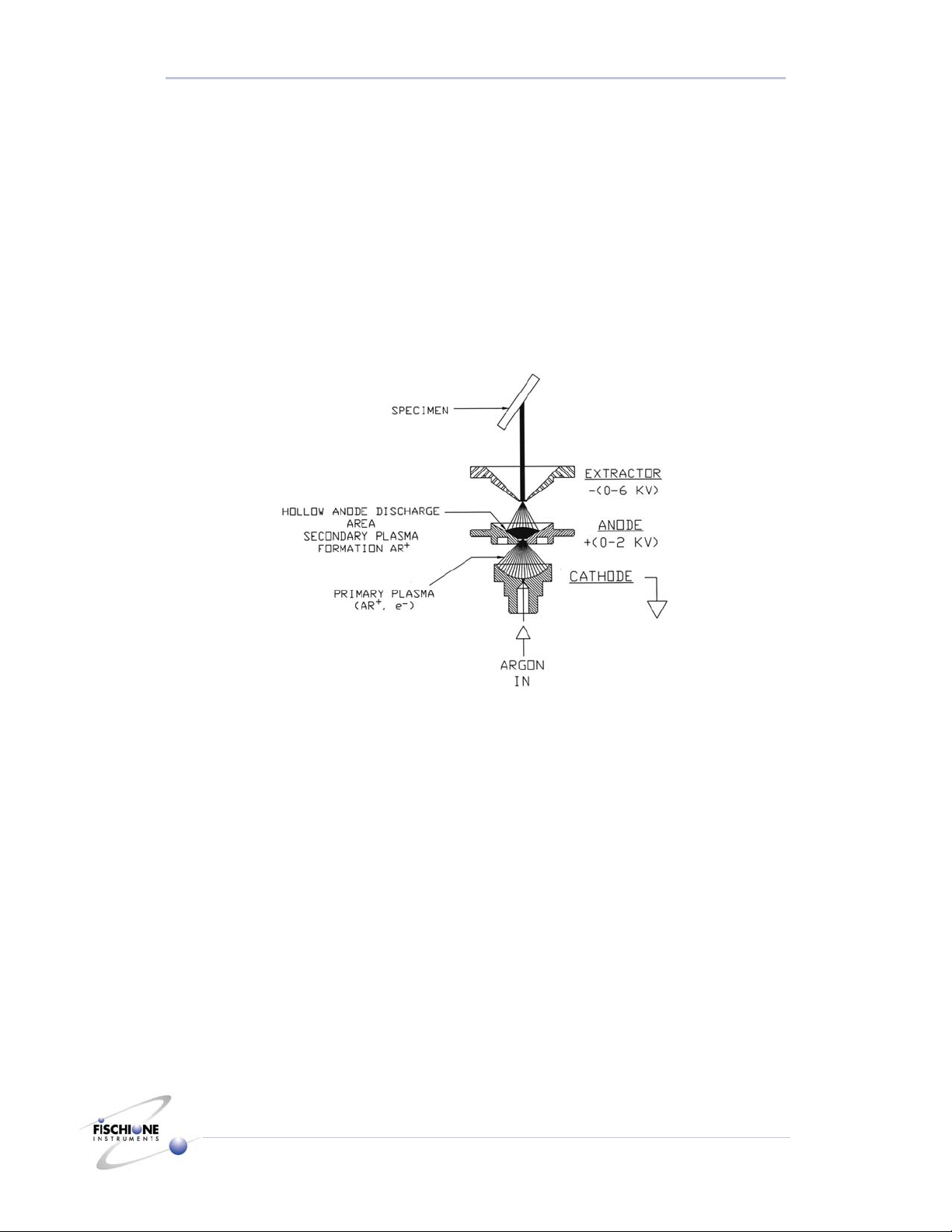
Ion Milling Theory
Ion milling uses an impinging incident HAD (Hollow Anode Discharge) ion to remove
(“sputter”) ions from the surface of a sample.
If an inert gas (for example, Ar or Ar+) is used for milling, sputtering is the result of
momentum transfer between the incident ion and the sample surface. If a reactive gas is
used, sputtering is enhanced by chemical reactivity.
Model 1010 Features
The Model 1010 is fully programmable, with features including two independently
adjustable Hollow Anode Discharge (HAD) ion sources which permit either rapid milling
or more gradual specimen polishing, automatic gas control, an oil-free vacuum system, a
milling angle range of 0 to 45°, specimen rotation or rocking, an optional liquid nitrogen
cooled specimen stage and optional automatic termination.
Sam
p
le Material
θ= 0 to 90o
Ar +
Sputtered
Sample
Material
Background
3 Model 1010 Ion Mill
Standard Magnification Version
The choice of single or dual ion source operation allows milling from either one or both
sides of the specimen. When using the Model 1010, total ion milling time is typically less
than two hours depending on the specimen material and its initial thickness.
Ion Sources
The Hollow Anode Discharge (HAD) ion sources operate over user-selectable ranges of
extractor voltage (0.5 kV to 6.0 kV) and current (3 mA to 8 mA), and are capable of
producing ion beam currents up to 400 microamps. To a first approximation, varying
voltage varies the average ion energy, while varying current varies the ion flux. The
milling rate for a given material generally increases as either parameter is increased. They
are fabricated from a combination of aluminum, brass, ceramics, polymers, and stainless
steel.
Hollow Anode Discharge (HAD) ion source.
Basic Procedure for Sample Preparation and Ion Milling
1. Mechanically section (cleave, saw) the sample.
2. Ultrasonically cut disks (3 mm diameter by <500 µm thick).
3. Rough grind (3 mm diameter by <75 µm thick).
4. Dimple grind (3 mm diameter by <10 µm center thickness).
5. Ion mill the top and bottom surfaces until they are electron transparent (3 mm
diameter by <100 nm thick).
6. Plasma clean.
System Overview
4 Model 1010 Ion Mill
Standard Magnification Version
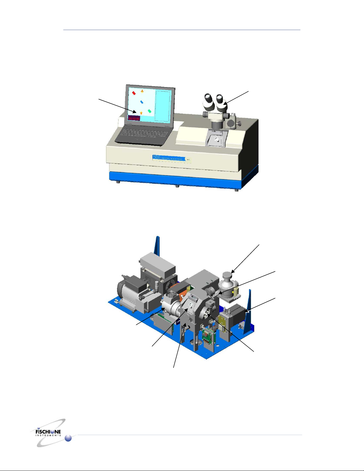
System Overview
Turbomolecular pump (TMP)
Ion source
Mass flow
controller (MFC)
LN2
Dewar
Dewar rod
Microscope
Sample chamber
Process control
computer
Front access door
System Overview
5 Model 1010 Ion Mill
Standard Magnification Version
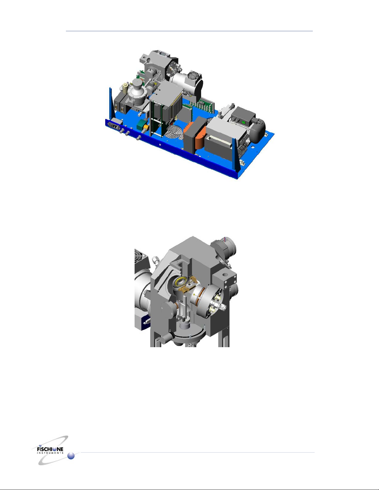
Sample Chamber
The sample chamber is fabricated from a single block of aluminum. The ion sources are
connected to the chamber via mounting and alignment flanges. Radial o-ring seals ensure
the vacuum integrity between the ion sources and the chamber.
Bottom: A vacuum flange mounted on the chamber bottom contains:
●The Pirani gauge for sensing vacuum.
●The bottom lamp assembly for observing the specimen using transmitted light.
●The detector for milling termination.
Rear: The rear of the chamber includes:
●The specimen stage rotator assembly.
●A series of electrical connections.

System Overview
6 Model 1010 Ion Mill
Standard Magnification Version
●The specimen rotation drive motor.
●The angle adjustment drive motor.
●The vacuum pumping port for the liquid nitrogen Dewar flask.
●The optical pick-up and encoder, which provides the milling angle indication.
Top: The top chamber surface includes:
●The top light assembly
Front: The front of the chamber includes:
•The electro-mechanical leak valve
•The chamber access door
Vacuum System
The Model 1010 is equipped with a 70 lps (minimum) turbomolecular vacuum pump. A
fan creates a constant air flow across the turbo pump cooling vanes to minimize the heat
associated with maintaining a vacuum under gas flow conditions. The Model 1010 also
includes an external rough pump. This is a diaphragm pump that provides backing
vacuum for the turbomolecular pump.
With no gas flow, ultimate chamber vacuum is 1 x 10⁻⁶ torr. Under normal milling
conditions, the system vacuum is between 1 x 10⁻⁴ and 2 x 10⁻⁵ torr. Total pump down
time is typically less than four minutes, although this time may vary based on ambient
temperature and relative humidity as well as the length of time that the chamber front
access door was open exposing the chamber to ambient conditions. Pump down times are
also increased following ion source cleaning or chamber maintenance.
The turbomolecular pump is directly mounted to the chamber by two bolts. An inlet
protection screen prevents debris from entering the pump and damaging the turbine
blades.
An electro-mechanical vent valve is installed directly onto the chamber and all venting is
controlled through the computer. Vacuum is sensed by a Pirani gauge and is continuously
indicated in the Ion Milling Program screen. In order to improve ion source performance,
argon flows through the ion sources during the venting process.
The specimen chamber vents through the normally closed solenoid valve located on the
front of the chamber. When the vacuum system is de-energized, both the diaphragm and
the turbomolecular pumps are turned off and voltage is applied to the vent valve. The
vent valve slowly bleeds ambient air into the chamber over approximately 20 seconds to
minimize stress on the rotary turbine blades in the turbo pump.
When liquid nitrogen is being used, venting will not occur until the specimen stage
temperature reaches +10°C, to prevent contamination of the specimen.
If the main instrument power switch is turned off while the vacuum system is energized,
the vacuum will be maintained, keeping the chamber sealed and free from ambient
contamination.

System Overview
7 Model 1010 Ion Mill
Standard Magnification Version
Gas Flow
The Model 1010 contains an internal, automatic gas control system. Process gas (usually
argon) is connected to the bulkhead fitting located on the rear of the instrument. The
purity of argon should be equal to or greater than 99.998% and supplied at a pressure of
10 psi (69 Mpa).
Two independently controlled mass flow controllers, located in a feedback control loop,
supply the appropriate amount of argon flow to the ion sources (between 0.4 sccm and
1.0 sccm). An internal pressure regulator is pre-set to provide the proper supply pressure
to the mass flow controllers.
The computer continuously monitors ion source performance and provides the
appropriate control signal to the flow controllers. The controllers are supplied with an
inlet voltage of +15 vdc and the control signal is 0-5 vdc proportional.
Water Flow
The high ion energies associated with the HAD (Hollow Anode Discharge) ion source
benefit from water cooling which both enhances performance and increases the time
interval between routine source maintenance. Cooling water circulates through the
alignment flange, which contains and is in thermal contact with the ion source cartridge.
Water enters the instrument though a bulkhead fitting on the rear panel. A solenoid valve
located within the instrument enclosure is normally closed. When the ion sources are
energized, the solenoid valve opens allowing water flow into the alignment flanges, thus
cooling the ion sources. A solenoid valve conserves water by only permitting flow when
required to cool an energized ion source.
The temperature of the inlet water is not critical but should be maintained between +5°C
and room temperature. Water flow of approximately 0.5 lpm is recommended. In the
unlikely event of the drain line becoming obstructed, the Model 1010 will not sense the
loss of flow. Therefore, periodically during operation, confirm that water is being drained
from the instrument.
Sample Cooling Capability (Optional)
A sample can be milled in the Model 1010 while actively being cooled to temperatures
approaching that of liquid nitrogen. The source of this cooling capability is an insulated
vessel (or “Dewar”) containing liquid nitrogen. A thermal path is provided by a
conduction rod passing through the Dewar to the rear of the sample stage. The maximum
temperature allowed during milling is selectable. It is selectable through the “Thermal
Safeguard” in the Ion Milling program.
To optimize the sample cooling capability, a vacuum must be maintained in the space
between the walls of the Dewar. Periodically the sample stage heater may need to be
activated to remove absorbed moisture and regenerate the Zeolite® desiccant. These
processes are controlled by the Dewar Bakeout program.
Endpoint Detection Capability (Optional)
The Model 1010 can be programmed to automatically de-energize the ion sources when
either a perforation in the sample is achieved or when the sample permits the
transmission of laser light. The detector circuitry is designed with a variable sensitivity

System Overview
8 Model 1010 Ion Mill
Standard Magnification Version
range. The scale is 1 to 10, with 1 being the most sensitive. These values are selectable in
the Ion Milling Program.
Note: Termination thresholds vary greatly based upon material and the desired
perforation size. Experimentation with varying parameters is necessary to obtain the
optimum termination point for different types of materials.
Visual Monitoring
The progress of an ion milling operation is monitored visually by using the standard
magnification stereo microscope. The magnification range with 10X eyepieces is 7 –
45X.
Control System and Software
All operations are controlled using four independent software programs.
Ion Milling Program Controls the milling operation. Allows the user to select milling parameters and
create the conditions necessary for manual or automatic operations.
Dewar Bakeout Program Controls the heating process for maintaining the Dewar insulation and Zeolite®
desiccant. Opens the vacuum connection, raises the temperature, and controls
the time at temperature
Laser Detector Calibration
Program
Calibrates the laser detector according to the transmissive properties of the
window protecting the laser sensor. Allows the user to choose the minimum
and maximum sensitivity values.
Data Logging Program Controls logging, retrieval, and display of milling parameters.
Specifications
Ion source type Hollow Anode Design
Ion source settings range Voltage: 0.5 – 6 kV, Current 3 – 8 mA
Specimen motion Full rotation (360o) or oscillation (0 to +/- 179o)
Milling rate Varies with material
Control platform PC compatible
Dimensions 33 in. wide by 19.5 in. deep by 26.5 in. high
Weight 115 lb (52 kg)
Power requirements 60 Watts
Water requirements Temperature of the inlet water is not critical but should be maintained between
+5°C and room temperature. Water flow should be approximately 0.5 lpm.
Gas requirements Argon equal to or greater than 99.998% and supplied at a pressure of 10 psi
(69 MPa)
Microscope capability 7-45X stereo zoom microscope
Turbomolecular vacuum
pump
70 lps (minimum). With no gas flow, ultimate chamber vacuum is 1 x 10⁻⁶ torr.
Under normal milling conditions, the system vacuum is between 1 x 10⁻⁴ and 2
x 10-5 torr

Installation and Setup
9 Model 1010 Ion Mill
Standard Magnification Version
Installation and Setup
Warnings, Cautions, and Notes
WARNING! LIFTING HAZARD. Do not try to lift the Model 1010 from the box
with only one person. The ion mill weighs about 115 pounds (52 kg).
WARNING! ELECTRICAL HAZARD. High voltages can cause severe injury or
death. Do not connect the power cord until after making gas and
water connections and after installing the microscope and computer.
Before disconnecting the power cord from the instrument, turn off
the instrument. Wait one minute to ensure that any charged
electronic component will discharge.
WARNING! COMPRESSED GAS HAZARD. High-pressure gas stream can
injure exposed skin or eyes. Point tubing away from personnel while
connecting or disconnecting gas cylinders.
CAUTION: Do not attempt to open the instrument enclosure while the
microscope or laser is installed. Remove the microscope, laser, and
post assembly before initiating service. Opening the Model 1010
while these components are installed could damage the microscope
and the enclosure.
CAUTION: Do not energize the ion sources unless Argon gas is supplied.
CAUTION: Do not energize the ion sources without a specimen in the specimen
holder. Failure to follow this caution will result in the ion beams
milling the outer components of the opposing ion source.
The Model 1010 is recommended for operation in an ambient temperature range of 12°C
to 40°C, and a relative humidity range of 10% to 70%.
The ion mill requires about 1 square meter of bench space.
Assessing initial condition
1. If the shipment has been received in good condition, proceed with unpacking.
2. If the shipment has been received with obvious damage, contact E.A. Fischione
Instruments before proceeding.
Unpacking and Inspecting
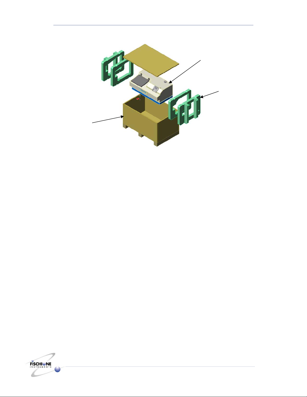
1. Remove the top of the crate.
2. Remove the accessory carton.
WARNING! LIFTING HAZARD. The ion mill weighs about 115 pounds. Use two
people to lift the ion mill.
3. Use two people to lift the Model 1010 from the base plate.
Installation and Setup
10 Model 1010 Ion Mill
Standard Magnification Version
4. Place the Model 1010 on a firm surface where it can be accessed from front and back.
5. Tilt the Model 1010 and remove the foam inserts.
6. Remove the Model 1010 from the plastic shipping bag.
Note: Save the shipping crate and packing materials in case the Model 1010 needs to
be returned to the factory for repair or maintenance.
7. Examine the outside of the Model 1010 for visible damage.
8. If there is evidence of damage, contact both the freight carrier and E.A. Fischione
Instruments before proceeding.
9. Place the Model 1010 on the surface where it will be operated.
Accessories
1. Open the box containing the accessories. This box includes:
•Microscope, microscope and spacer
•Specimen loading station and accessories
•Tool set
•Optional laser, Dewar cap, and / or exhaust kit if ordered
2. Inspect all components in this box for signs of damage.
3. If there is evidence of damage, contact both the freight carrier and E.A. Fischione
Instruments before proceeding.
Model 1010
Foam insert
Packing crate
Installation and Setup
11 Model 1010 Ion Mill
Standard Magnification Version
Connections
WARNING! ELECTRICAL HAZARD. High voltages can cause severe injury or
death. Do not connect the power cord until after making gas and
water connections and after installing the microscope and computer.
Process gas
Note: For plasma processing, E.A. Fischione Instruments recommends using argon with a
grade equal to or better than 99.998% purity.
WARNING! COMPRESSED GAS HAZARD. High-pressure gas stream can
injure exposed skin or eyes. Point tubing away from personnel while
connecting or disconnecting gas cylinders.
1. Position the process gas supply so that it is located within five feet of the ion mill.
2. Mount a suitable pressure regulator (Victor HPT 270 or equivalent) onto the process
gas supply.
3. Connect the ¼ in. tubing (supplied) between the pressure regulator on the process gas
supply and the gas inlet quick-connection on the rear of the Model 1010.
4. Tighten the connection 1¼ turns after finger tight.
5. Open both the cylinder and the process gas supply valves.
6. Adjust the cylinder pressure regulator to a pressure of 10 psi (69 MPa).
7. Close the process gas cylinder valve and observe the cylinder pressure regulator
gauge. The indicated pressure should remain constant for a minimum of five minutes.
This action ensures that the process gas connection is properly sealed.
8. Open the process gas cylinder valve.
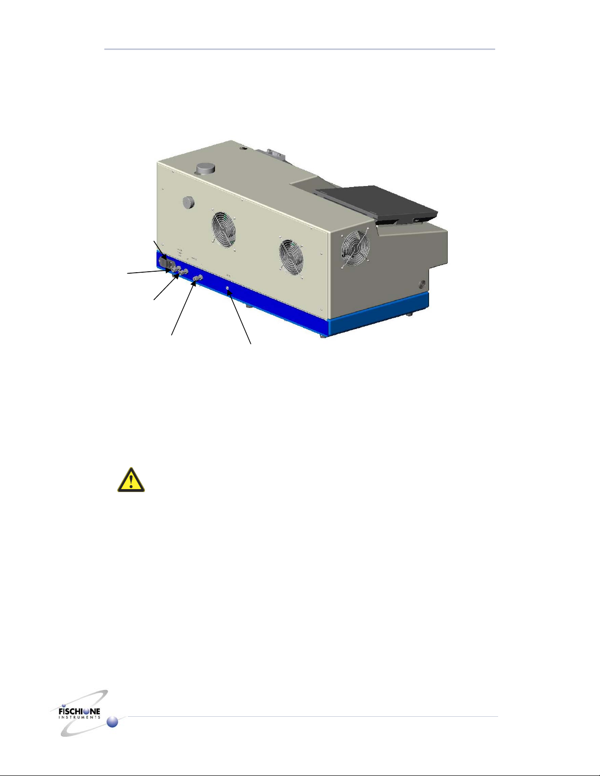
Mains (power)
Gas
Water Out
Water In Laser
Installation and Setup
12 Model 1010 Ion Mill
Standard Magnification Version
Exhaust gas
If hazardous materials will be inserted into the Model 1010 for processing, the ion mill
must be connected directly to an exhaust system capable of accommodating the
hazardous material.
1. If the optional exhaust installation kit was purchased (P/N 009-0285) from E.A.
Fischione Instruments, it includes the fitting and length of tubing required for making
this connection.
Using gas tubing and fittings other than those specified is not recommended and will
void the warranty.
2. Remove the small plastic muffler from the pump exhaust.
3. Thread the connector into the pump exhaust.
4. Press the included Viton® tubing over the barb connector.
5. Connect the exhaust of the diaphragm pump to a suitable fume hood or equivalent
venting system.
Water
The Model 1010 Ion Mill requires a minimum water flow of 0.5 liters per minute (lpm).
Water temperature should be maintained at or below room temperature.
E.A. Fischione Instruments recommends using an in-line filtering system.
1. Connect ¼ in. tubing (not supplied) between the water inlet and outlet and the two
quick-connections on the rear of the Model 1010.
2. Tighten the connections 1¼ turns after finger tight.
Microscope Installation
1. Place the spacer over the end of the microscope post.

Installation and Setup
13 Model 1010 Ion Mill
Standard Magnification Version
2. Insert the microscope post through the cutout on top of the enclosure, into the
threaded hole
3. Rotate the microscope post clockwise until tight
4. Assemble the stereo microscope. Install the 10X eyepieces after removing their
individual lens caps, and then remove the lens cap on the microscope’s lens
5. Install the microscope onto its post, lowering its mount until it contacts the spacer
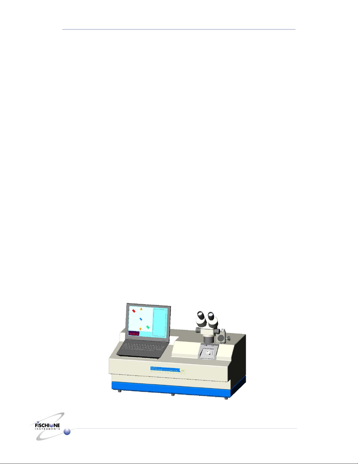
High magnification microscope installed
Process Control Computer
The process control computer is shipped already installed. The connections to the rear of
the computer should be checked before operation.
Coarse and fine
focus knobs
Hei
g
ht ad
j
ustment
Process control
computer
Sample chamber

Installation and Setup
14 Model 1010 Ion Mill
Standard Magnification Version
Laser Installation (optional)
Note: The laser will not be illuminated while conducting this procedure. The laser is
turned on during milling operations.
1. Lift and swing the microscope out of the way.
2. Connect the male connector of the laser cable to the receptacle on the rear of the
instrument.
3. Insert the laser into the receptacle above the top viewing window.
4. When not being used, insert the laser into the receptacle located on top of the
microscope post.
Power Connections
For US application
1. Verify that the operating voltage matches the requirements of the Model 1010.
The power entry module is equipped with two 6-amp fuses for 110 VAC operation
and two 3-amp fuses for 220VAC operation.
2. Connect the power cord between the power entry module and a suitable receptacle.
For non-US application
1. Attach a suitable connector to the bare wires of the power cord (supplied) using the
following color-coding:
Blue = Neutral (0V)
Brown = Phase (Line, AC)
Green and yellow striped = Ground (earth)
2. Verify that the operating voltage matches the requirements of the Model 1010.
110, 220, or 240 VAC can be used with the appropriate fuse.
3. Connect the power cord between the power entry module and a suitable receptacle.
Laser
Cable plug
Chamber insert
with viewin
g
window

Installation and Setup
15 Model 1010 Ion Mill
Standard Magnification Version
To change operating voltage
Model 1010 has been configured to operate with the operating voltage of the country of
the original purchase order. If the Model 1010 is to be used under other power conditions,
contact E.A. Fischione Instruments for more information. The instrument must be
reconfigured by a qualified service technician or returned to factory.

Operation
16 Model 1010 Ion Mill
Standard Magnification Version
Operation
CAUTION: Do not install any program onto the Model 1010 Ion Mill computer.
Installing other programs, including word processing and data
management programs, could interfere with the real-time control of
the ion mill and will void the warranty.
CAUTION: Never attempt to force or pry open the chamber insert. To insert a
specimen, the vacuum must be off and the stage temperature must
be at least 10°C.
Basic Startup Procedure
1. Verify that the ion mill is supplied with electricity, gas, and water.
2. Press the switch on the lower rear instrument panel (mains) to ON.
3. Press and hold the power button on the computer until the computer boots up.
A user identification dialog box will appear.
4. Click OK.
Note: “Click” means to use the touch pad on the computer to move the pointer
into position then press the left button of the touch pad.
The desktop screen will appear with icons for four Model 1010 programs:
•Dewar Bakeout
•Log Viewer
•Ion Mill
•Laser Calibration (if applicable)
Ion mill on/off
switch (on back)
Computer on/off
switch
Table of contents


