Fisher Engineering Minute Mount 2 EZ-V 95150 User manual
A DIVISION OF FISHER, LLC
CAUTION
Read this document before installing the
snowplow.
CAUTION
See your FISHER® outlet/website for specic
vehicle application recommendations before
installation. The eMatch selection system has
specic vehicle and snowplow requirements.
7'6" EZ-V®Snowplow
Installation Instructions
Fisher Engineering
July 15, 2020
Lit. No. 74916, Rev. 01
95150, 95160, 95180-3, 95190-3
50 Gordon Drive, Rockland, Maine 04841‑2139 • www.sherplows.com

Lit. No. 74916, Rev. 01 2 July 15, 2020
95150, 95160, 95180-3, 95190-3
SAFETY DEFINITIONS
NOTE: Indicates a situation or action that can lead
to damage to your snowplow and vehicle or other
property. Other useful information can also be
described.
CAUTION
Indicates a potentially hazardous situation
that, if not avoided, may result in minor or
moderate injury. It may also be used to alert
against unsafe practices.
WARNING/CAUTION AND INSTRUCTION
LABELS
Become familiar with and inform users about the
warning labels on the back of the blade and the
instruction label on the headgear.
NOTE: If labels are missing or cannot be read, see
your sales outlet.
WARNING
Indicates a potentially hazardous situation
that, if not avoided, could result in death or
serious personal injury.
Instruction Label
Warning/Caution Label

Lit. No. 74916, Rev. 01 3 July 15, 2020
95150, 95160, 95180-3, 95190-3
HYDRAULIC SAFETY
• Always inspect hydraulic components and hoses
before using. Replace any damaged or worn parts
immediately.
• If you suspect a hose leak, DO NOT use your
hand to locate it. Use a piece of cardboard or
wood.
FUSES
The FISHER® electrical and hydraulic systems
contain several automotive‑style fuses. If a problem
should occur and fuse replacement is necessary,
the replacement fuse must be of the same type and
amperage rating as the original. Installing a fuse with
a higher rating can damage the system and could start
a re. Fuse Replacement, including fuse ratings and
locations, is located in the Maintenance section of the
Owner's Manual.
PERSONAL SAFETY
• Remove the ignition key and put the vehicle in
PARK or in gear to prevent others from starting
the vehicle during installation or service.
• Wear only snug‑tting clothing while working on
your vehicle or snowplow.
• Do not wear jewelry or a necktie, and secure long
hair.
• Wear safety goggles to protect your eyes from
battery acid, gasoline, dirt, and dust.
• Avoid touching hot surfaces such as the engine,
radiator, hoses, and exhaust pipes.
• Always have a re extinguisher rated BC handy,
for ammable liquids and electrical res.
WARNING
Hydraulic uid under pressure can cause skin
injection injury. If you are injured by hydraulic
uid, get medical attention immediately.
SAFETY PRECAUTIONS
Improper installation and operation could cause
personal injury and/or equipment and property damage.
Read and understand labels and the Owner's Manual
before installing, operating, or making adjustments.
WARNING
Lower the blade when vehicle is parked.
Temperature changes could change
hydraulic pressure, causing the blade to
drop unexpectedly or damaging hydraulic
components. Failure to do this could result in
serious personal injury.
WARNING
Remove blade assembly before placing
vehicle on hoist.
WARNING
The driver shall keep bystanders clear of the
blade when it is being raised, lowered, or
angled. Do not stand between vehicle and
blade or within 8 feet of a moving blade. A
moving or falling blade could cause personal
injury.
WARNING
Do not exceed GVWR or GAWR, including
blade and ballast. The rating label is found on
driver-side vehicle door cornerpost.
WARNING
To prevent accidental movement of the blade,
always turn the control OFF whenever the
snowplow is not in use. The power indicator
light will turn OFF.
WARNING
Keep hands and feet clear of the blade and
T-frame when mounting or removing the
snowplow. Moving or falling assemblies could
cause personal injury.
CAUTION
Refer to the current eMatch selection system
for minimum vehicle recommendations and
ballast requirements.

Lit. No. 74916, Rev. 01 4 July 15, 2020
95150, 95160, 95180-3, 95190-3
FIRE AND EXPLOSION
Be careful when using gasoline. Do not use gasoline
to clean parts. Store only in approved containers away
from sources of heat or ame.
CELL PHONES
A driver's rst responsibility is the safe operation of
the vehicle. The most important thing you can do
to prevent a crash is to avoid distractions and pay
attention to the road. Wait until it is safe to operate
mobile communication equipment such as cell phones,
text messaging devices, pagers, or two‑way radios.
VENTILATION
BATTERY SAFETY
NOISE
Airborne noise emission during use is below 70 dB(A)
for the snowplow operator.
VIBRATION
Operating snowplow vibration does not exceed
2.5 m/s2 to the hand‑arm or 0.5 m/s2 to the whole
body.
CAUTION
Batteries normally produce explosive gases,
which can cause personal injury. Therefore,
do not allow ames, sparks, or lit tobacco
to come near the battery. When charging or
working near a battery, always cover your
face and protect your eyes, and also provide
ventilation.
• Batteries contain sulfuric acid, which burns
skin, eyes, and clothing.
• Disconnect the battery before removing or
replacing any electrical components.
WARNING
Vehicle exhaust contains lethal fumes.
Breathing these fumes, even in low
concentrations, can cause death. Never
operate a vehicle in an enclosed area without
venting exhaust to the outside.
WARNING
Gasoline is highly ammable and gasoline
vapor is explosive. Never smoke while
working on vehicle. Keep all open ames
away from gasoline tank and lines. Wipe up
any spilled gasoline immediately.

Lit. No. 74916, Rev. 01 5 July 15, 2020
95150, 95160, 95180-3, 95190-3
TORQUE CHART
1/4-20 10
91
54
1/4-28 12
11
71
5/16-1
81
50 212
5/16-2
41
70 240
3/8-16 269 376
3/8-24 29
74
20
7/16-1442
96
06
7/16-20
9/16-12
9/16-18
5/8-11
5/8-18
3/4-10
3/4-16
7/8-9
7/8-14 47
46
69
64
49
091-8
1-12 70
49
95
1/2-13
1/2-20
11.9
13.7
24.6
27.3
43.6
26.9
53.3
93
148
49.4
69.8
77.9
106.4
120.0
8.4
9.7
17.4
19.2
30.8
35.0
49.4
55.2
75.3
85.0
M6 x 1.00
M12 x 1.75
M8 x 1.25
M14 x 2.00
M10 x 1.50
M27 x 3.00
M22 x 2.50
M30 x 3.50
M24 x 3.00
M20 x 2.5011.1
19.5
38.5
67
107
7.7
613
778
1139
1545
450
428
562
796
1117
M33 x 3.50
M36 x 4.00
2101
2701
1468
1952
325
M16 x 2.00 231167
M18 x 2.50 318222
Recommended Fastener Torque Chart
Size Size
Torque (ft-lb)
Grade
5
Grade
8
Metric Fasteners Class 8.8 and 10.9
These torque values apply to fasteners
except those noted in the instructions.
Torque (ft-lb)
Grade
5
Grade
8
Size Size
Torque (ft-lb)
Class
8.8
Class
10.9
Torque (ft-lb)
Class
8.8
Class
10.9
Inch Fasteners Grade 5 and Grade 8
CAUTION
Read instructions before assembling.
Fasteners should be nger tight until
instructed to tighten according to the torque
chart. Use standard methods and practices
when attaching snowplow, including proper
personal protective safety equipment.
HEADGEAR TO T-FRAME ASSEMBLY
NOTE: For easier assembly and installation, the
vehicle and all snowplow components should
be on a smooth, level, hard surface, such as
concrete.
1. With the vehicle parked on a solid, level surface,
measure the distance from the center of the
connecting pin hole to the ground. Refer to the
table below to determine which T‑frame hole
should be used to attach the headgear to the push
assembly. If the vehicle is unavailable, use hole 2
and reposition the headgear later if necessary.
Pushplate Height
(hole center to ground)
T-Frame
Hole
14.25" to 15.5" 1
13.0" to 14.25" (typical) 2
11.75" to 13.0" 3
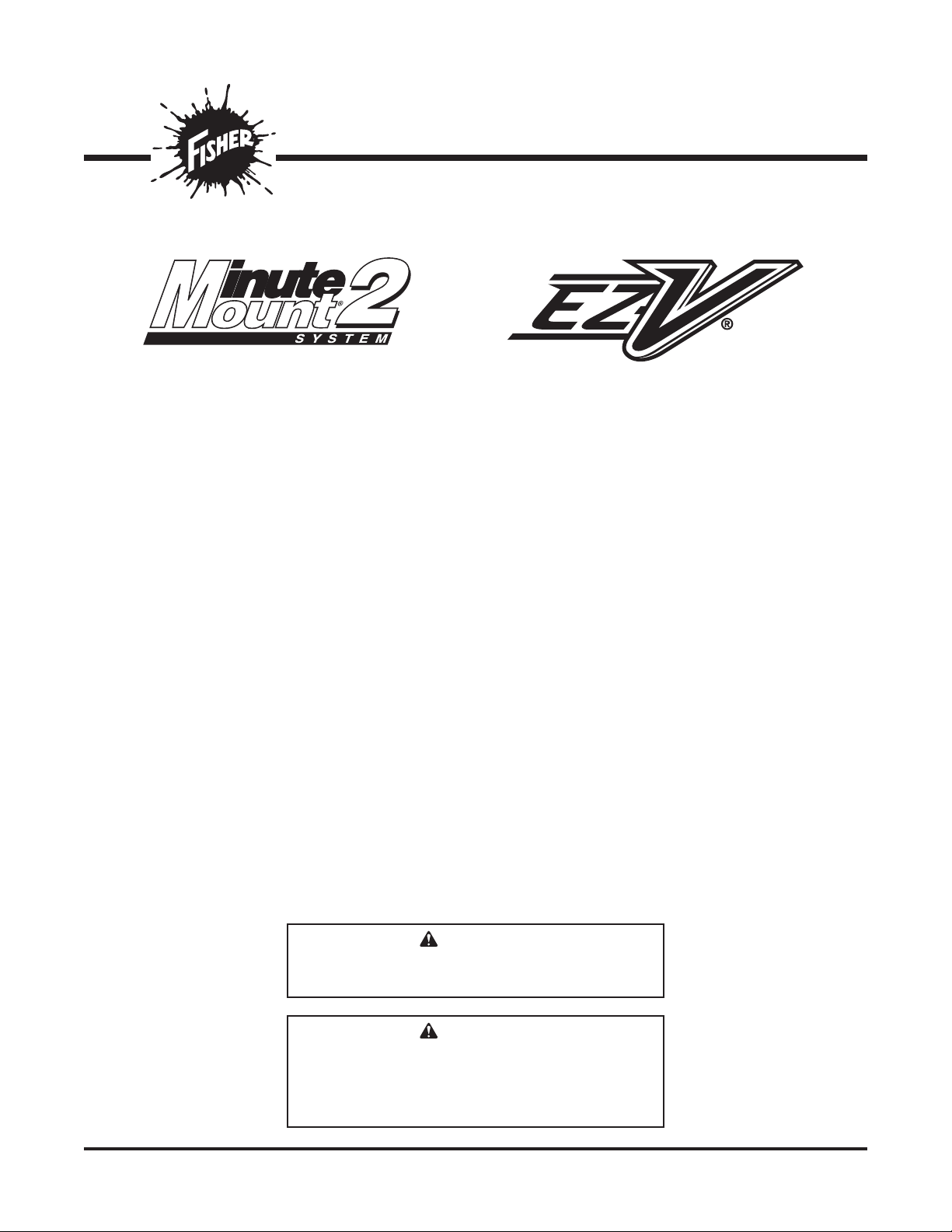
2. Set aside the pivot pin, parts bags, and blade
guides.
Measure
this distance.
Center of
Connecting
Pin Hole
Hole 1
Hole 2
Hole 3
Lit. No. 74916, Rev. 01 6 July 15, 2020
95150, 95160, 95180-3, 95190-3
3. Remove the hardware and blocking that secures
the T‑frame to the pallet.
4. Remove the strapping that secures the headgear
to the T‑frame.
5. While supporting the headgear, remove the self‑
tapping screw from each shipping bracket and
discard.
6. Remove the cable ties and discard. Remove and
retain the 3/4" x 2‑1/2" clevis pins. Discard the
shipping brackets.
7. Remove the packaging from the lift chain so that
it has enough slack for the headgear to move
upward as necessary.
8. Align the headgear holes with the T‑frame holes
selected above. Connect the headgear to the
T‑frame by installing the two 3/4" x 2‑1/2" clevis
pins from the outside of the headgear through
both sets of holes. Install 3/4" at washers and
5/32" x 1‑1/2" cotter pins from the parts bag to the
clevis pins.
3/4" x 2-1/2"
Clevis Pin
5/32" x 1-1/2"
Cotter Pin
3/4"
Flat Washer
Lit. No. 74916, Rev. 01 7 July 15, 2020
95150, 95160, 95180-3, 95190-3
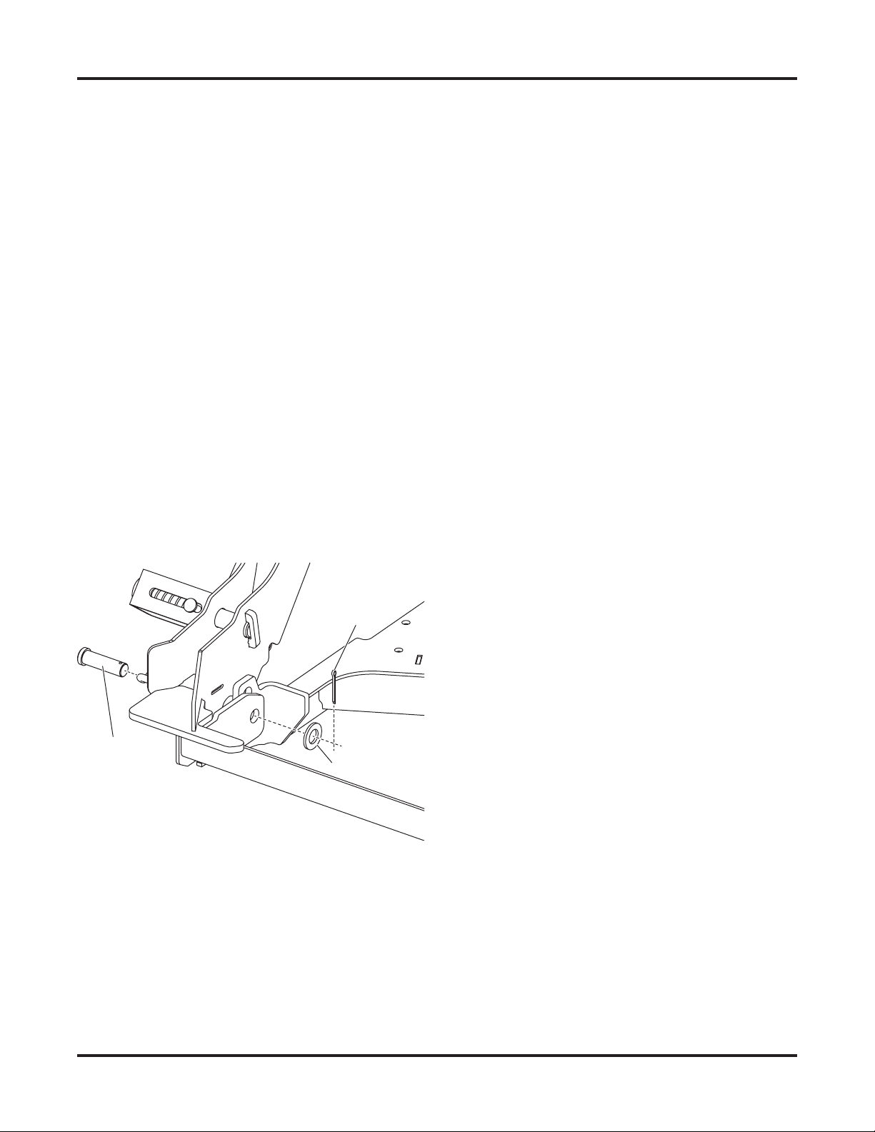
T-FRAME TO BLADE ASSEMBLY
1. Remove the blade wings from the metal shipping
brackets. Discard the shipping brackets and
replace the cutting edge hardware.
2. Align the hinges of the blade wings. Position the
T‑frame assembly between the blade wings so
that the pivot holes in the T‑frame are aligned with
the holes in the wing hinges.
3. Insert the pivot pin from top to bottom through all
the hinges as shown below.
4. With the snowplow in normal operating position,
pull the jack lock to lower the jack to support the
headgear. Release the jack lock to hold the jack in
position.
Pivot Pin
1/2" x 2-7/8"
Clevis Pins
5/32" x 1-1/2"
Cotter Pins
Jack Handle
Jack Lock
Jack
5. Remove the protective packaging from the
angle rams.
6. Align the holes in the rod ends of each angle ram
with the corresponding holes on the back of the
blade.
7. Install a 1/2" x 2‑7/8" clevis pin from the top to
secure each rod to the blade. Secure the clevis
pins with 5/32" x 1‑1/2" cotter pins as shown.
8. Install the center snow deector using two
3/8" x 1‑1/2" cap screws and 3/8" locknuts.
9. Install the blade guides, using two 7/16" lock
washers and two 7/16" nuts for each guide.
Snow
Deflector
3/8" x
1-1/2"
Cap Screw
3/8"
Locknut
Blade Guide
7/16" Lock
Washers
7/16" Nu
ts

Lit. No. 74916, Rev. 01 8 July 15, 2020
95150, 95160, 95180-3, 95190-3
6. Secure the snowplow harnesses and wires to the
headgear with cable ties as shown.
HEADLAMPS
Headlamps, hardware, and instructions are found in
the headlamp box.
1. Install the vehicle wiring according to the
instructions provided.
2. With the driver‑ and passenger‑side headlamps on
the correct sides, set each headlamp and swivel
into place on the headgear light bar.
3. Secure the headlamps with the correct hardware
for the application as shown below. Inner and
outer posts require dierent hardware. On LED
headlamps, a rubber washer must be installed
under the slotted holes. Hand tighten fasteners.
4. Connect the headlamp wires to the headlamps.
5. Aim the headlamps according to the Snowplow
Headlamp Beam Aiming Instructions
(Lit. No. 27769). For LED headlamps,
tighten the fasteners to 22 ft‑lb (30 N·m). For
halogen headlamps, tighten the fasteners to
50 ft‑lb (68 N·m).
WARNING
Your vehicle must be equipped with snowplow
headlamps and directional lights.
Halogen Headlamps LED Headlamps
Headlamp
Swivel
Headgear
Light Bar
1/2" Flat
Washers
1/2" Lock
Washers
1/2" Hex Nuts
Slotted
Hole
1/2" Rubbe
r
Washer
Cable
Ties
Snowplow
Li
ghting
Harness
Lit. No. 74916, Rev. 01 9 July 15, 2020
95150, 95160, 95180-3, 95190-3
HYDRAULIC UNIT
The EZ‑V® snowplow hydraulic unit comes from the
factory pre‑assembled, partially lled, and fully tested.
1. Attach the snowplow to the vehicle according to
the instructions on the blade label.
2. Remove the cover from the hydraulic unit.
3. Remove and discard the factory‑installed pipe
plug from the top of the reservoir and install the
breather.
WARNING
Keep 8' clear of the blade when it is being
raised, lowered, or angled. Do not stand
between the vehicle and the blade or directly
in front of the blade. If the blade hits or drops
on you, you could be seriously injured.
Breather
Fill
Plug
Drain
Cap
Pipe
Plug
AeroShell® is a registered trademark (®) of Shell Oil Company.
4. Turn the control ON and completely extend and
retract the driver‑side wing several times. Repeat
for the passenger‑side wing. With both wings fully
retracted, raise and lower the snowplow several
times. Activate the control FLOAT function and
manually collapse the lift ram all the way. Turn the
control OFF.
5. Remove the ll plug and check the uid level.
With the snowplow wings and lift ram fully
retracted, the uid level should reach the ll hole.
If additional uid is needed, ll the reservoir
with FISHER® EZ Flow Hydraulic Fluid rated
to –40°F (–40°C), or other uid conforming to
Military Specication MIL‑H‑5606 A, such as
Mobil Aero HFA or Shell AeroShell® Fluid 4.
NOTE: Remove the ll plug slowly to relieve any
pressure in the reservoir.
NOTE: Add uid only when all rams are retracted.
6. Replace and tighten the ll plug.
CAUTION
Do not mix dierent types of hydraulic uid.
Some uids are not compatible and may cause
performance problems and product damage.
FLUID CAPACITY
• Insta‑Act® Unit Reservoir 1‑3/4 quarts
• Insta‑Act System Total 2‑1/8 quarts
WARNING
To prevent accidental movement of the blade,
always turn the control OFF whenever the
snowplow is not in use. The power indicator
light will turn OFF.
Lit. No. 74916, Rev. 01 10 July 15, 2020
95150, 95160, 95180-3, 95190-3
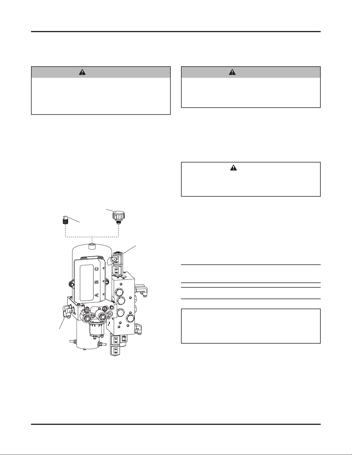
BLADE DROP SPEED ADJUSTMENT
The quill in the valve manifold adjusts the blade drop
speed.
1. Lower the blade to the ground before making
adjustments.
2. Turn the quill IN (clockwise) to decrease drop
speed. Turn the quill OUT (counterclockwise) to
increase drop speed.
3. Stand 8 feet clear of the blade when checking
adjustment.
4. Replace the hydraulic unit cover.
WARNING
Keep 8' clear of the blade when it is being
raised, lowered, or angled. Do not stand
between the vehicle and the blade or directly
in front of the blade. If the blade hits or drops
on you, you could be seriously injured.
Quill

Lit. No. 74916, Rev. 01 11 July 15, 2020
95150, 95160, 95180-3, 95190-3
2. Remove and retain the U‑bolt and locknuts that
secure the lift chain on the passenger's side of the
T‑frame. Reposition the U‑bolt in the chain so that
the chain is the same length as the chain on the
driver's side.
3. Reinstall the U‑bolt in the T‑frame and tighten the
locknuts. The chain link should pivot freely in the
U‑bolt.
4. Raise and lower the snowplow in the fully
retracted (vee) position to verify that the hydraulic
hoses bow outward and do not interfere with
snowplow components.
NOTE: Ensure that the base-end angle ram hoses
are wrapped over the diagonal brace. Adjust
hoses, ttings, and wraps as necessary to prevent
any hoses from being pinched.
FINAL ADJUSTMENTS
Lift Chain
1. Adjust the length of the lift chain on the
driver's side (with attached spring) so that the
T‑frame hits the T‑frame stop when the lift ram is
fully extended (10").
WARNING
Keep 8' clear of the blade when it is being
raised, lowered, or angled. Do not stand
between the vehicle and blade or directly in
front of the blade. If the blade hits or drops on
you, you could be seriously injured.
10"
T-Frame
Stop

Lit. No. 74916, Rev. 01 12 July 15, 2020
95150, 95160, 95180-3, 95190-3
Adjusting the Lift Chain Spring
The lift chain spring ensures proper operation of the
snowplow mounting system by providing slack in the
lift chain after the blade is lowered.
The EZ‑V® snowplow comes with the connecting
chain link of the lift chain spring factory‑installed in
the eighth link up from the driver‑side lift chain U‑bolt.
However, due to variations in vehicle frame height,
it may be necessary to adjust the spring location to
ensure optimal performance.
If you encounter mounting or dismounting diculty,
the attachment point of the connecting chain link and
spring can be changed to add or remove slack from
the lift chain.
With the snowplow attached to a properly ballasted
vehicle, make one of the following adjustments:
If there is not enough slack in the lift chain:
Adjust the connecting chain link up one link from
the factory setting.
If there is too much slack in the lift chain:
Adjust the connecting chain link down one link
from the factory setting.
Moving the connecting chain link more than one chain
link higher or lower than the original factory setting is
not recommended.
Lift Chain (DS)
Center U-Bolt
Spring
Connecting
Chain Link
Driver-Side
U-Bolt
Link #1
Connecting
Chain Link

Lit. No. 74916, Rev. 01 13 July 15, 2020
95150, 95160, 95180-3, 95190-3
Adjusting the Center Cutting Edges
The center cutting edge spacer plate is located on the
T‑frame below the pivot pin hinge.
1. Place the blade wings in the retracted (vee)
position and check whether the center cutting
edges touch the center cutting edge spacer plate.
If they do not touch the spacer plate, adjust the
center cutting edges as follows.
2. Loosen the four 5/8" x 2" center cutting edge
carriage bolts, but do not remove them.
3. Slide the center cutting edges inward until they
contact the spacer plate.
4. Re‑tighten the center cutting edge carriage bolts
according to the torque chart.
5/8"
x 2"
Ca
rriage BoltsSpacer Plate
Center Cutting Edge
Spacer Plate
Lubricating the Pivot Pin Hinge
Using a rubber‑tipped seal‑o coupler tting, apply a
good quality multipurpose grease at the ve grease
points along the center hinge of the blade.
Grease
Points

Lit. No. 74916, Rev. 01 14 July 15, 2020
95150, 95160, 95180-3, 95190-3
With headlamp switch OFF, activate the vehicle
DRLs.
Snowplow lighting harness DISCONNECTED:
• Vehicle DRLs should be ON.
• Snowplow headlamps should be OFF.
Snowplow lighting harness CONNECTED and
vehicle in DRL mode:
• Check snowplow DRL function per the type of
Isolation Module installed.
Refer to the Mechanic's Guide for information on
the Isolation Module DRL functions.
Joystick or Hand‑Held Control
The snowplow plugs do need to be connected to
the vehicle harness connectors. The control power
indicator light should light whenever the control
ON/OFF switch and the ignition (key) switch are
both in the "ON" position.
3. Connect all snowplow and vehicle harnesses.
Raise the snowplow and aim the snowplow
headlamps according to the Snowplow Headlamp
Beam Aiming instructions included with the
headlamps, and any state or local regulations.
4. Check the aim of the vehicle headlamps with the
snowplow removed.
NOTE: On 2-plug electrical systems, plug
covers shall be used whenever the snowplow is
disconnected.
5. When the snowplow is removed from the vehicle,
install plug covers on the vehicle battery cable
and lighting harness. Insert the snowplow battery
cable and lighting harness into the cable boot on
the snowplow.
VEHICLE LIGHTING CHECK
1. Verify the operation of all vehicle front lighting
prior to connecting the snowplow harness.
2. Check the operation of the snowplow headlamps
with snowplow mounted to vehicle and all
harnesses connected.
Turn signals and parking lamps
Parking lamps ON:
• Both vehicle and snowplow parking lamps
should be ON at the same time.
Driver‑side turn signal ON:
• Both vehicle and snowplow driver‑side turn
signal lamps should ash at the same time.
Passenger‑side turn signal ON:
• Both vehicle and snowplow passenger‑side
turn signal lamps should ash at the same time.
Headlamps
Move vehicle headlamp switch to the
"ON" position. Connecting and disconnecting the
snowplow lighting harness plug should switch the
lights between vehicle and snowplow as follows:
Snowplow lighting harness DISCONNECTED:
• Vehicle headlamps should be ON.
• Snowplow headlamps should be OFF.
Snowplow lighting harness CONNECTED:
• Snowplow headlamps should be ON.
• Vehicle headlamps should be OFF.
Dimmer switch should toggle headlamps between
high and low beams. The high beam indicator on
the dash should light when headlamps are placed
in high beam.
Daytime Running Lamps (DRLs)
An operational check of the vehicle and snowplow
DRLs will depend on the vehicle model and DRL
system and the type of Isolation Module installed.
Due to variations in OEM DRL systems and
the dierent Isolation Module options available,
checking functionality of the snowplow DRLs will
depend on the type of module installed on the
vehicle.

Lit. No. 74916, Rev. 01 15 July 15, 2020
95150, 95160, 95180-3, 95190-3
OWNER'S MANUAL PACKET
If the completed snowplow will be delivered
immediately, the Owner's Manual should be reviewed
with and given to the purchaser according to the
snowplow checklist.
If the snowplow is completed prior to delivery to the
purchaser, attach the Owner's Manual packet to the
electrical cable of the cab control for safekeeping.

Lit. No. 74916, Rev. 01 16 July 15, 2020
95150, 95160, 95180-3, 95190-3
Fisher Engineering reserves the right under its product improvement policy to change construction or design details and furnish equipment
when so altered without reference to illustrations or specications used. Fisher Engineering or the vehicle manufacturer may require or
recommend optional equipment for snow removal. Do not exceed vehicle ratings with a snowplow. Fisher Engineering oers a limited warranty
for all snowplows and accessories. See separately printed page for this important information. The following are registered (®) trademarks of
Douglas Dynamics, LLC: EZ‑V®, FISHER®, Insta‑Act®, Minute Mount®2.
Printed in U.S.A.
This manual suits for next models
3
Other Fisher Engineering Snow Blower manuals


