Fisher Engineering Insta-Act Snowplow User manual

Fisher Engineering
September 6, 2001
Lit. No. 26469
Insta-Act®Hydraulic Power Unit
Installation Instructions
Table of Contents
Safety Information .................................................................................................................... 2
Attach Mounting Brackets to Insta-Act Hydraulic Power Unit .............................................. 3
Attach Hydraulic Fittings to Cylinders .................................................................................... 3
Attach Lift and Angle Cylinders ............................................................................................... 4
Mount Insta-Act Hydraulic Power Unit .................................................................................... 5
Route Hydraulic Hoses to Valve Fittings ................................................................................ 6
Install Snowplow Control Harness and Cable ....................................................................... 7
Final Adjustments ..................................................................................................................... 8
9828-2
P.O. Box 529 Rockland, Maine 04841
®
Snowplow
CAUTION
Read this document before installing
the snowplow.
A DIVISION OF DOUGLAS DYNAMICS, L.L.C.

September 6, 2001 2 Lit. No. 26469
9828-2
WARNING
Indicates a potentially hazardous situation that,
if not avoided, could result in death or serious
personal injury.
WARNING
Remove blade assembly before placing
vehicle on hoist.
PERSONAL SAFETY
• Wear only snug-fitting clothing while working on
your vehicle or snowplow.
• Do not wear jewelry or a necktie, and secure long
hair.
• Wear safety goggles to protect your eyes from
battery acid, gasoline, dirt and dust.
• Avoid touching hot surfaces such as the engine,
radiator, hoses and exhaust pipes.
• Always have a fire extinguisher rated BC handy, for
flammable liquids and electrical fires.
SAFETY PRECAUTIONS
Improper installation and operation could cause
personal injury, and/or equipment and property damage.
Read and understand labels and the Owner’s Manual
before installing, operating, or making adjustments.
WARNING
Keep well clear of the blade when it is being
raised, lowered or angled. Do not stand
between the vehicle and blade or directly in
front of blade. If the blade hits you or drops on
you, you could be seriously injured.
WARNING
Lower blade when vehicle is parked.
Temperature changes could change hydraulic
pressure, causing the blade to drop
unexpectedly or damaging hydraulic
components. Failure to do this can result in
serious personal injury.
CAUTION
Refer to the Kit Selection Guide for minimum
vehicle recommendations and ballast
requirements.
CAUTION
To prevent accidental movement of the blade,
always turn the ON/OFF switch to OFF
whenever the snowplow is not in use. The
control indicator light will turn off.
NOTE: Identifies tips, helpful hints and
maintenance information the owner/operator
should know.
SAFETY INFORMATION
CAUTION
Indicates a situation that, if not avoided, could
result in damage to product or property.
WARNING
The driver shall keep bystanders clear of the
blade when it is being raised, lowered or
angled. Do not stand between the vehicle and
the blade or within 8 feet of a moving blade. A
moving or falling blade could cause personal
injury.
WARNING
Do not exceed GVWR or GAWR including
blade and ballast. The rating label is found on
driver-side vehicle door cornerpost.
WARNING
Keep hands and feet clear of the blade and
A-frame when mounting or removing the
snowplow. Moving or falling assemblies could
cause personal injury.

Lit. No. 26469 3 September 6, 2001
9828-2
HYDRAULIC SAFETY
• Always inspect hydraulic components and hoses
before using. Replace any damaged or worn parts
immediately.
• If you suspect a hose leak, DO NOT use your hand
to locate it. Use a piece of cardboard or
BATTERY SAFETY
FIRE AND EXPLOSION
Be careful when using gasoline. Do not use gasoline to
clean parts. Store only in approved containers away
from sources of heat or flame.
VENTILATION
WARNING
Gasoline is highly flammable and gasoline
vapor is explosive. Never smoke while
working on a vehicle. Keep all open flames
away from gasoline tanks and lines. Wipe up
any spilled gasoline immediately.
WARNING
Vehicle exhaust contains deadly carbon
monoxide (CO) gas. Breathing this gas, even
in low concentrations, could cause death.
Never operate a vehicle in an enclosed area
without venting exhaust to the outside.
CAUTION
Always disconnect the battery before removing
or replacing electrical components such as a
motor relay or battery cable.
CAUTION
Batteries normally produce explosive gases
which can cause personal injury. Therefore,
do not allow flames, sparks or lit tobacco to
come near the battery. When charging or
working near a battery, always cover your
face and protect your eyes, and also provide
ventilation.
Batteries contain sulfuric acid which burns
skin, eyes and clothing.
Disconnect the battery before removing or
replacing any electrical components.
TORQUE CHART
CAUTION
Read instructions before assembling. Bolts
should be finger tight until instructed to tighten
according to the torque chart. Use standard
methods and practices when attaching
snowplow including wearing safety glasses
during cutting, drilling and welding.
WARNING
Hydraulic oil under pressure could cause skin
injection injury. If you are injured by hydraulic
oil, get medical attention immediately.
Recommended Fastener Torque
Chart (Ft.-Lb.)
Size SAE
Grade 2
SAE
Grade 5
SAE
Grade 8
1/4-20
5/16-18
3/8-16
3/8-24
7/16-14
1/2-13
9/16-12
5/8-11
3/4-10
7/8-9
1-8
6
11
19
24
30
45
66
93
150
150
220
9
18
31
46
50
75
110
150
250
378
583
13
28
46
68
75
115
165
225
370
591
893
Metric Grade 8.8 (Ft.-Lb.)
Size TorqueSize
Torque
M 6
M 8
M 10
M 12
M 14
M 16
7
17
35
60
95
155
These torque values apply to mount assembly fasteners
except those noted in the instruction.
September 6, 2001 4 Lit. No. 26469
9828-2
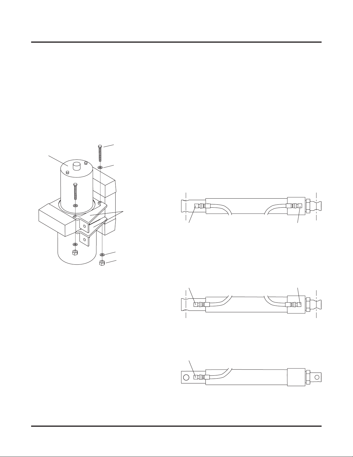
1. Attach the mounting brackets to the valve block
with two 1/4 x 3" cap screws, flat washers and
locknuts.
2. Tighten cap screws.
ATTACH HYDRAULIC FITTINGS TO
CYLINDERS
ATTACH MOUNTING BRACKETS TO
INSTA-ACT® HYDRAULIC POWER UNIT
Angle Cylinders
1. Remove threaded plugs from cylinders using an
Allen wrench.
2. Attach fittings (street elbows) to angle cylinders as
shown. Fittings must be oriented to direct hoses
parallel to cylinders. Do not use thread sealant/tape
on hoses or fittings. This could damage product.
3. Attach 36" hoses to fittings in angle cylinders.
1/4 NPT x
90° Street
Elbow
1/4 NPT x
90° Street
Elbow
1/4 NPT x
90° Street
Elbow
1/4 NPT x
90° Street
Elbow
Passenger Side Angle Cylinder
Driver Side Angle Cylinder
Angle Cylinder Fittings
Hoses parallel to
cylinder.
Lift Cylinder Fittings
9/16 O-Ring to
1/4 NPT 90° Elbow
Mounting
Brackets
Hydraulic
Unit
Locknut
Flat Washer
1/4 X 3" Cap Screw
Flat Washer
Lit. No. 26469 5 September 6, 2001
9828-2
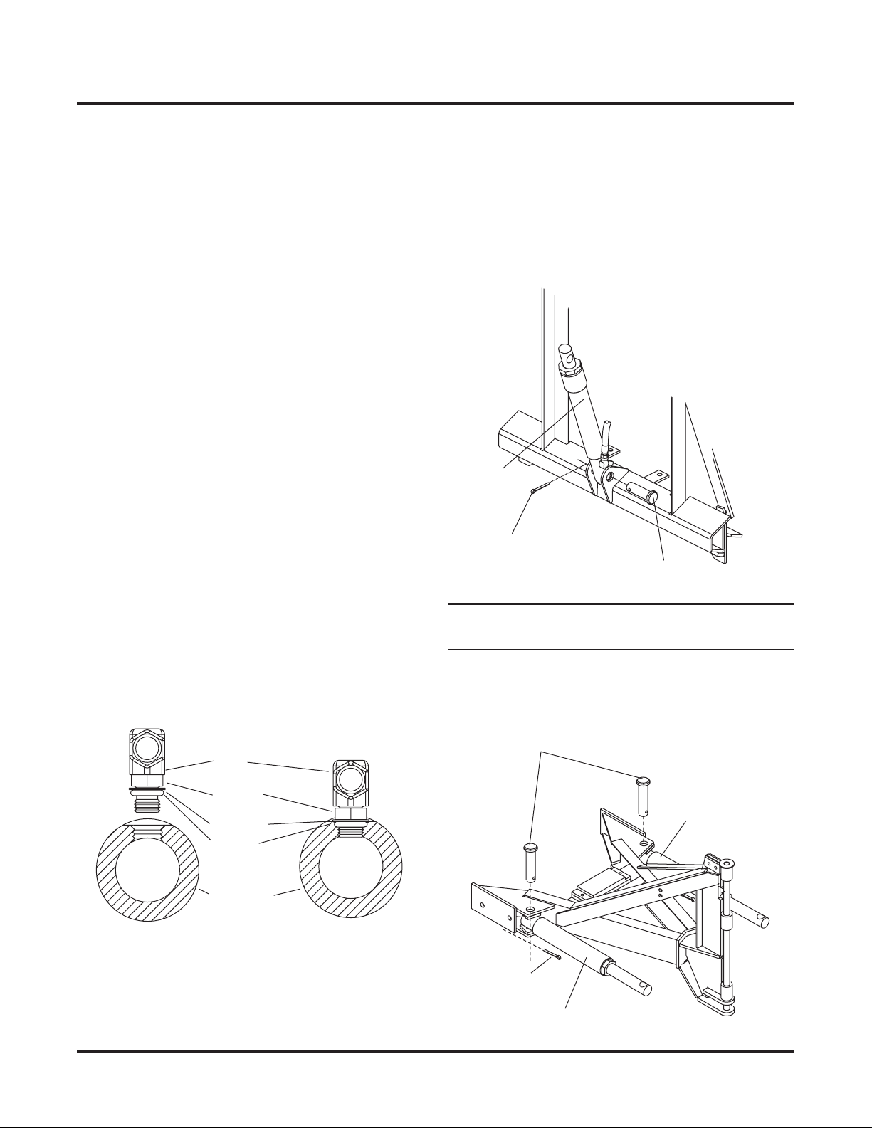
Lift Cylinders with SAE O-Ring Port
1. Turn the jam nut on the fitting as far back as
possible.
2. Lubricate the O-Ring with clean hydraulic oil.
Remove the plug from the cylinder port.
3. Screw fitting into port by hand as far as it will go.
The washer should contact port face and shoulder
of the jam nut threads.
4. Unscrew fitting to proper position, no more than one
full turn.
5. Use one wrench to hold the fitting body in position
and tighten the jam nut with another wrench until
the washer again contacts port face. Tighten 1/8 to
1/4 turn to lock fitting in place.
6. Attach the 18" HP hose to the lift cylinder elbow.
7. Tighten hose on to the fitting until finger tight.
8. Hold the hose from turning and tighten the hose
swivel nut 1/4 turn.
ATTACH LIFT AND ANGLE CYLINDERS
1. Attach the lift cylinder to the headgear with a
1 x 3-5/16" clevis pin and 1/4 x 1-1/2" cotter pin.
Position the hydraulic port so it faces the driver's
side of the snowplow.
NOTE: For 9-1/2' EZ-V®Blades, install blade stop kit
26634 before attaching angle cylinders.
2. Attach the angle cylinders to the A-frame with the
two anchor pins and cotter pins. Position the fittings
so they face inward, toward the A-frame.
Anchor Pins
Cotter Pin
Angle Cylinder
Angle Cylinde
r
Lift
Cylinder
1/4 x 1-1/2" Cotter Pin
1 x 3-5/16" Clevis Pin
Fitting
Jam Nut
Washer
O-Ring
Cylinder
September 6, 2001 6 Lit. No. 26469
9828-2
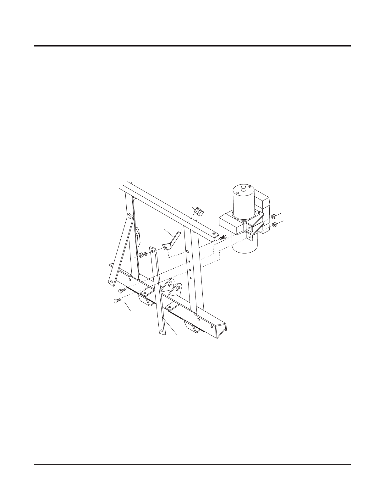
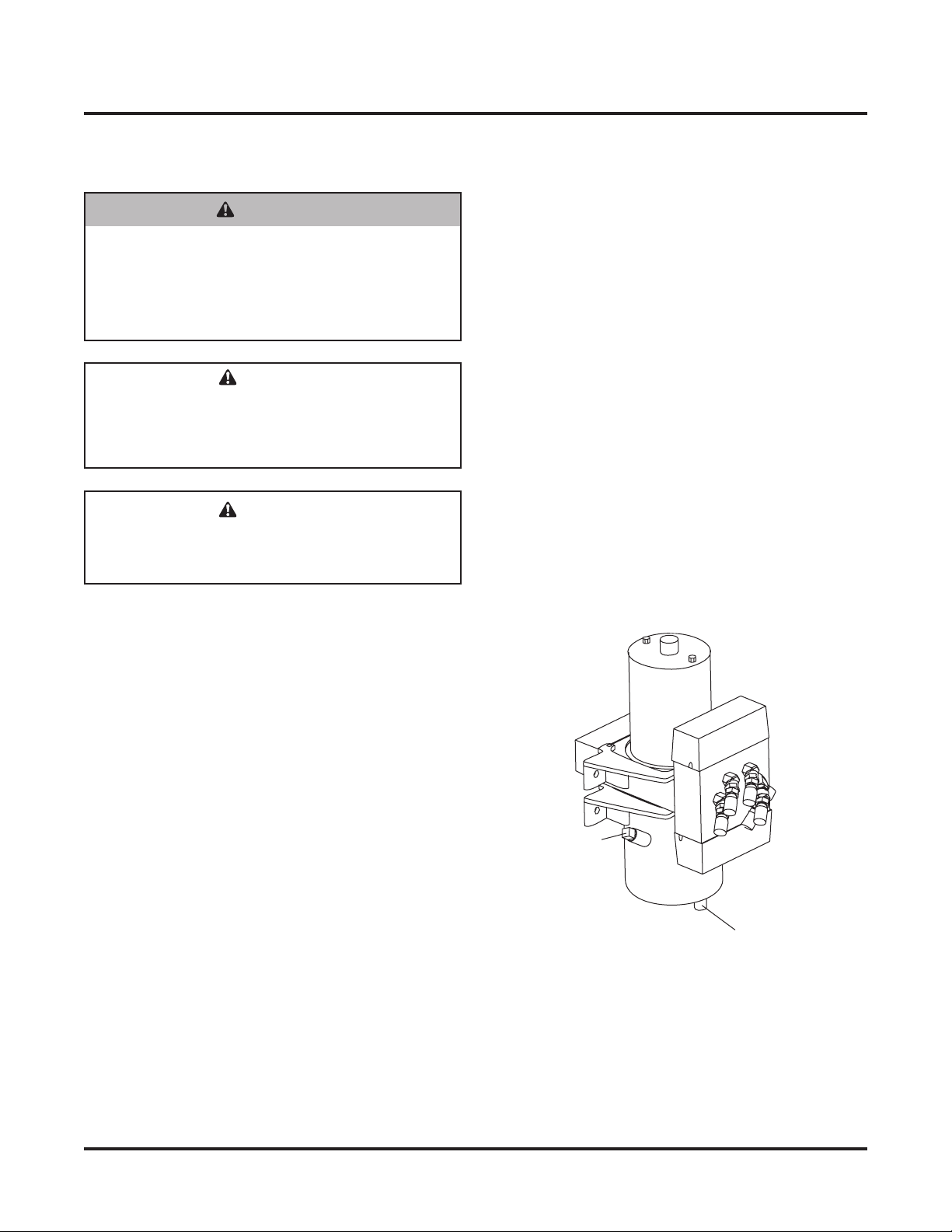
MOUNT INSTA-ACT® HYDRAULIC POWER
UNIT
1. Remove the top bolt from the passenger side
headgear brace. Loosen the bottom bolt on the
passenger side headgear brace. Swing the brace
out of the way.
2. Bolt the hydraulic unit to the headgear using two
3/8 x 1-1/4" cap screws and locknuts. Use the top
two holes if three holes are available.
Headgear
Brace
3/8 x 1-1/4"
Cap Screws
Cable Boot
Bracket
Cable
Boot
3. Reattach and tighten the headgear brace.
4. Install the cable boot and cable boot bracket on the
passenger side headgear brace, reusing the cap
screw and flanged locknut already in place.
Lit. No. 26469 7 September 6, 2001
9828-2
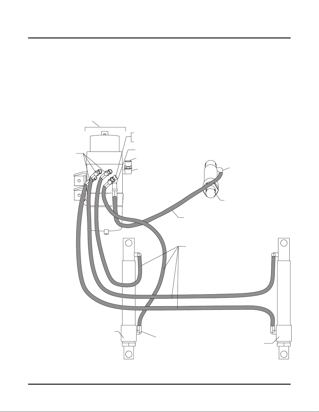
ROUTE HYDRAULIC HOSES TO VALVE
FITTINGS
18" Hose, HP 1/4 P - 1/4 P
36" Hose, HP 1/4P - 1/4P
Lift Cylinder
1/4 NPT x 45° Swivel
A
dapter Union
1/4 NPT x 45° Street Elbow
and 1/4 NPT Straight Adapter Union
1/4 NPT x 90° Swivel Adapter Union
Hydraulic Unit
Driver-Side
Angle Cylinder
1/4 NPT x 90° Street Elbow
(4 places)
Passenger-Side
Angle Cylinder
A
B
C
ED
Breather - 3/8 NPT
3/8 NPT x 90° Street Elbow
9/16 O-Ring to
1/4 NPT 90° Elbow
1. Attach the fittings and hoses to the hydraulic unit
and cylinders as shown. Attach the fittings
beginning at point A and proceed in alphabetical
order to point E.
2. Remove the 3/8" plug from tapped port on driver
side of primary valve block. Attach 90° elbow and
breather.
September 6, 2001 8 Lit. No. 26469
9828-2
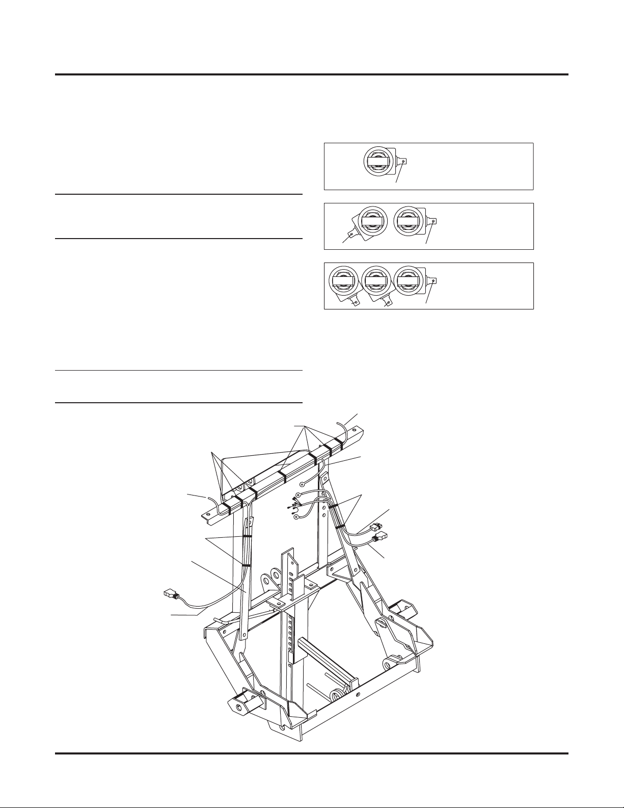
INSTALL SNOWPLOW CONTROL
HARNESS AND CABLE
1. Remove the solenoid covers. Connect the snowplow
control harness to the valve blocks according to the
instructions inside the solenoid covers.
NOTE: The strain reliefs must be inside the cover to
prevent unnecessary strain on the solenoid
connectors.
COILS - 5 ft. lbs.
CARTRIDGES - 10 ft. lbs.
SOLENOID VALVE TORQUE:
RED WIRE TABS, ONE AT EACH COIL.
COLORED WIRES AS SHOWN.
ELECTRICAL CONNECTIONS:
BLUE/ORANGE
4W COIL
66618
BLACK/WHITE COILS - 5 ft. lbs.
CARTRIDGES - 10 ft. lbs.
SOLENOID VALVE TORQUE:
RED WIRE TABS, ONE AT EACH COIL.
COLORED WIRES AS SHOWN.
ELECTRICAL CONNECTIONS:
LT. BLUE/ORANGE
3W COIL
3W COIL
66617
WHITE/YEL.
2W COIL
COILS - 5 ft. lbs.
CARTRIDGES - 10 ft. lbs.
SOLENOID VALVE TORQUE:
RED WIRE TABS, ONE AT EACH COIL.
COLORED WIRES AS SHOWN.
ELECTRICAL CONNECTIONS:
4W COIL
GREEN
4W COIL
BLUE
66616
Cable Ties
From Light
Snowplow Control Harness
(plug into Snowplow Lighting
Harness for storage)
Snowplow Cable Assembly,
shrouded plug
(store in cable boot)
Snowplow Lighting
Harness, shrouded plug
Headgear Brace
Cable Ties
From Light
Cable Ties
Cable Ties Black/Orange ground wire
Rev. 3 and later harnesses
Connect to negative motor terminal
2. Attach the snowplow cable assembly to the motor
terminals located on the side of the motor body.
Connect the black and red striped wire to the
positive terminal. Connect the black wire to the
negative terminal.
3. Cable tie harnesses and cable assembly to the
headgear braces as shown.
NOTE: Snowplow lighting and control harnesses
plug into one another for storage.
Lit. No. 26469 9 September 6, 2001
9828-2
FINAL ADJUSTMENTS
1. Fill with FISHER®High Performance Hydraulic Fluid
to top of fill hole.
System Capacity:
Reservoir—1-3/4 quart
Complete System—2-1/2 quarts
2. Extend and retract the driver-side wing several
times. Return to the retracted position.
3. Extend and retract the passenger-side wing several
times. Return to the retracted position.
4. Add hydraulic fluid to the reservoir.
5. Raise and lower the snowplow several times. Return
to the lower position, retracting the cylinder
completely.
Fill Plug
Drain Plug
CAUTION
Do not mix different types of hydraulic fluid.
Some fluids are not compatible and may cause
performance problems and product damage.
CAUTION
DO NOT raise the blade during fill process as
this may cause pump cavitation.
WARNING
Keep well clear of the blade when it is being
raised, lowered or angled. Do not stand
between the vehicle and blade or directly in
front of blade. If the blade hits you or drops on
you, you could be seriously injured.
September 6, 2001 10 Lit. No. 26469
9828-2
Fisher Engineering reserves the right under its product improvement policy to change construction or design details and furnish equipment
when so altered without reference to illustrations or specifications used herein. Fisher Engineering and the vehicle manufacturer may require
and/or recommend optional equipment for snow removal. Fisher Engineering offers a limited warranty on all snowplows and accessories. See
separately printed page for this important information. The following are registered (®) trademarks of Douglas Dynamics, L.L.C.:
FISHER®, Insta-Act®, EZ-V®
Printed in USA
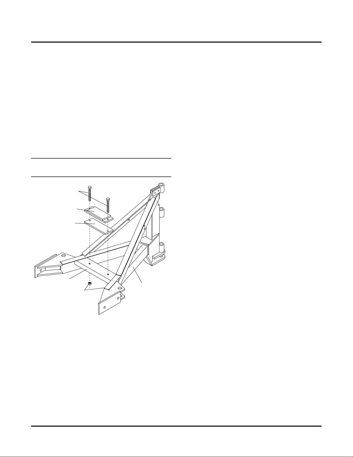
6. With the angling cylinders and lift cylinder retracted,
add enough additional hydraulic fluid so the fill plug
can just be replaced without overflowing.
7. Raise the lift cylinder to full extension. The lift
cylinder should have approximately 10" of lift and
the A-frame stop assembly should contact the lower
crossmember of the headgear. Lower the blade.
Adjust the length of the lift chain and adjust the
number of rubber plates on the stop kit so the A-
frame hits the headgear when the lift cylinder is fully
raised.
NOTE: In all cases, install at least one rubber
spacer plate and the stop assembly.
Cross Brace A-Frame
Assembly
Stop Assembly
Rubber Spacer
Plates
(3 provided)
3/8-16 Locknut
3/8-16 x 3"
Gr.5 Cap Screw
8. Torque the two 3/8 x 3" full thread cap screws and
3/8" locknuts to 31 ft-lb. Tighten both U-bolts.
Table of contents
Other Fisher Engineering Snow Blower manuals


