Shelves
Shipped inside each cabinet are 3 epoxy coated shelves
per door opening. Epoxy coated filler shelves are provid-
ed for units with more than one door. Shelf supports,
located in the plastic bag, are pushed into the side
pilasters, one in each corner, at the desired shelf height.
Replacement shelves are available individually. See
Replacement Parts for shelf part numbers. See Figure 2
for shelf installation.
Electrical Connection
Determine the total amount of current presently being
used by other apparatus connected to the circuit that will
be used by this freezer. It is critical that this added cur-
rent demand and other equipment on this circuit not
exceed the rating of the fuse or circuit breaker in use.
The frequency and nominal voltage requirements for the
unit are specified on the data plate, which is located on
the interiorʼs upper left side. Plug the unit only into a
power source that meets these requirements. Low line
voltage is often the cause of service complaints. With the
unit running, check that the line voltage is within ±10% of
that specified on the data plate.
The customer should have the wall receptacle and circuit
checked by a qualified electrician to verify the receptacle
is properly grounded and is connected to the proper
power supply. The following list gives the NE A
plug/receptacle configuration for the corresponding freez-
ers.
6
UNPACKING AND INS ALLA ION
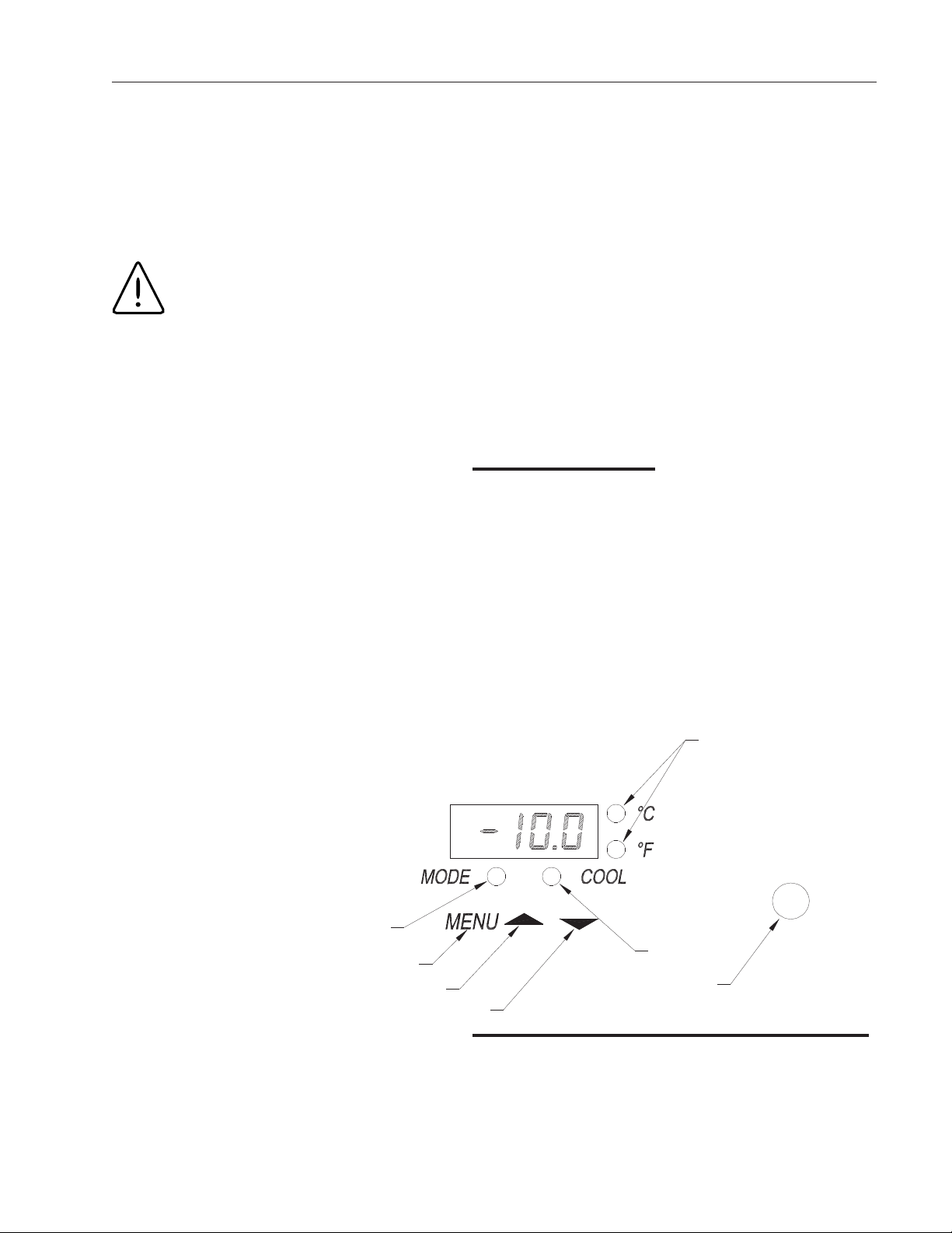
Caution
If the unit was tilted in excess of 30
degrees, level it and do not apply
electrical power for a minimum of 12
hours.
Warning
Be sure that the power supply is the
same voltage that is specified on the
freezerʼs data plate.
Warning
For personal safety this unit must be
properly grounded. DO NOT under
any circumstance cut or remove the
ground prong from the power cord.
DO NOT use a plug adapter that elimi-
nates the ground prong.
Lab Freezers (115V)
Catalog Noʼs NE A Plug NE A Receptacle
13-986-142 5-20P 5-20R
13-986-144 5-20P 5-20R
Lab Freezers (230V)
Catalog Noʼs NE A Plug NE A Receptacle
13-986-143 L14-20 L14-20
13-986-147 L14-20 L14-20
Caution
Do not use an extension cord. Use of
an ungrounded cord or an overloaded
circuit VOIDS the compressor warran-
ty.
Figure 2
Caution
Catalog numbers ending in HK are
international 3-Wire systems and
should not be confused with 230V
domestic units which are 4-Wire sys-
tems. Consult a qualified electrician
before powering this unit.