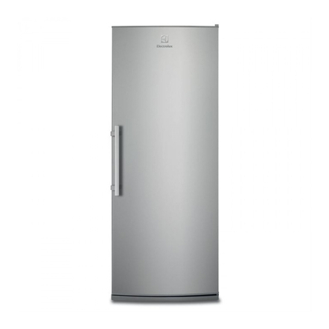
Fisher Scientific Isotemp 13-986-327L User manual

Isotemp®General Purpose
Laboratory Freezer
Catalog Numbers:
13-986-327L / 327LR / 327LA
LT2122X1 • 9/16/09

2
Table of Contents
Introduction..........................................................................................................................................................3
Safety Information ........................................................................................................................................3
Alert Signals..................................................................................................................................................3
Unpacking and Installation ..................................................................................................................................4
Visible Loss or Damage................................................................................................................................4
Concealed Loss or Damage ........................................................................................................................4
Packing List ..................................................................................................................................................5
Locating the Cabinet ....................................................................................................................................5
Installing the Cabinet ....................................................................................................................................5
Condensate Pan ..........................................................................................................................................6
Electrical Requirements................................................................................................................................6
Mounting the Shelves and Display Sensor ..................................................................................................7
Cabinet Start-Up ..........................................................................................................................................7
Thermostat Settings......................................................................................................................................9
Defrost Setting ............................................................................................................................................10
Operation ..........................................................................................................................................................10
Maintenance......................................................................................................................................................11
Cleaning the Interior ..................................................................................................................................11
Cleaning the Exterior ..................................................................................................................................11
Cleaning the Condenser ............................................................................................................................11
Condensate Pan ( eated) ..........................................................................................................................11
Removing Door ..........................................................................................................................................11
Energy Conservation Measures ................................................................................................................12
Troubleshooting ................................................................................................................................................13
Spare Parts ......................................................................................................................................................15
Wiring Diagram..................................................................................................................................................16
Warranty ............................................................................................................................................................20

3
Your satisfaction and safety are important to Fisher
Scientific and a complete understanding of this unit is
necessary to attain these objectives.
Before attempting installation, adjustment or maintenance,
be certain of the following:
1. That you have read and fully understand the
instructions.
2. That you have all the tools required and are
trained to use them.
3. That you have met all installation and usage
restrictions and are familiar with the functions
and operation of the unit.
4. That you follow all instructions exactly as given.
As the ultimate user of this apparatus, it is your responsi-
bility to understand its proper function and operational
characteristics. This instruction manual should be thor-
oughly read and all operators given adequate training
before attempting to place this unit in service. Awareness
of the stated cautions and warnings, and compliance with
recommended operating parameters – together with
maintenance requirements – are important for safe and
satisfactory operation. The unit should be used for its
intended application; alterations or modifications will void
the Warranty.
This pro uct is not approve for storage of flammable
or explosive materials. Also, it is not approve for
use in hazar ous locations containing explosive
atmospheres.
This pro uct is not inten e , nor can it be use , as a
sterile or patient connecte evice. In a ition, this
apparatus is not esigne for use in Class I, II or III
locations as efine by the National Electrical Co e,
unless otherwise note .
Safety Information
Warning
Warnings alert you to a possibility of
personal injury.
Caution
Cautions alert you to a possibility of
damage to the equipment.
Note
Notes alert you to pertinent facts and
conditions.
Hot Surface
ot surfaces alert you to a possibility
of personal injury if you come in con-
tact with a surface during use or for a
period of time after use.
Alert Signals
Warning
As a routine laboratory precaution,
always wear safety glasses when
working with this apparatus.
DANGER: RISK OF C ILD ENTRAP-
MENT. BEFORE YOU T ROW AWAY
YOUR OLD REFRIGERATOR OR
FREEZER:
• TAKE OFF DOORS
• LEAVE T E S ELVES IN T E
PLACE SO T AT C ILDREN
MAY NOT EASILY CLIMB INSIDE.

4
Unpacking and Installation
Save all packing material if apparatus is received dam-
aged. This merchandise was carefully packed and thor-
oughly inspected before leaving our factory.
Responsibility for its safe delivery was assumed by the
carrier upon acceptance of the shipment; therefore, claims
for loss or damage sustained in transit must be made
upon the carrier by the recipient as follows:
Visible Loss or Damage
Note any external evidence of loss or damage on the
freight bill, or express receipt, and have it signed by the
carrier’s agent. Failure to adequately describe such exter-
nal evidence of loss or damage may result in the carrier’s
refusing to honor your damage claim. The form required
to file such a claim will be supplied by the carrier.
Concealed Loss or Damage
Concealed loss or damage refers to loss or damage,
which does not become apparent until the merchandise
has been unpacked and inspected. Inspect the underside
of the cabinet and packaging for damage such as a fork
truck can cause, or look for bent base members from
dropping the cabinet. If concealed damage is found make
a written request to the carrier’s agent within 15 days of
the delivery date; then file a claim with the carrier since
the damage is the carrier’s responsibility.
If you follow the above instructions carefully, we will guar-
antee our full support of your claim to be compensated for
loss from concealed damage.
DO NOT – FOR ANY REASON – RETURN T IS UNIT
WIT OUT FIRST OBTAINING AUT ORIZATION.

UNPACKING AND INSTALLATION
Packing List
The following items are packed in the envelope located
inside the freezer chamber. If any of the following items
are not present, report the missing item to your local
Fisher representative.
1. Warranty Card
2. This Instruction Manual
3. Door Lock Key
4. Power Switch Key
5. Chart Recorder Instructions (Catalog No.’s with
“R” or “A”)
Locating the Cabinet
Select a location where the cabinet will not be exposed to
heat sources such as sun through windows heating vents,
etc. The location should provide 12 inches of clearance
above the cabinet and 2 inches on each side. The plug
supplying power to the cabinet should be close enough
so that no extension cord is needed.
Installing the Cabinet
Whenever possible, leave the crate skid on the cabinet
until it is moved close to the final position. When it is nec-
essary to move the cabinet through a doorway, it may be
necessary to remove the crate skid.
Wood runners are provided on the underside of the cabi-
net for ease in sliding. These runners shoul be left
attache to the cabinet when the ski is remove an
shoul remain attache until after the legs are
installe . The cabinet can then be pushed around more
easily without scratching the floor. The runners also pre-
vent damage to the electrical receptacle and condensate
pan hardware on the cabinet bottom.
After the cabinet has been moved to the approximate final
location, remove the package containing the legs from the
5

cabinet interior. Tape the doors to prevent accidental
opening while handling. Raise the sides of the cabinet
high enough to mount the legs at the locations provided
on the bottom of the cabinet.
Level the cabinet by means of the leg adjustments.
Cabinet doors ARE self-closing, and the cabinet must be
level to operate properly.
Allow a minimum of twelve (12) inches between the top of
the cabinet and ceiling for proper air circulation through
the condensing unit.
Condensate Pan (When supplied)
The condensate pan assembly mounts in the "track" pro-
vided on the underside of the cabinet. The pan assembly
must be pushed in from the front of the cabinet far
enough to be positioned under the condensate drain tube
on the backside of the cabinet.
The pan assembly must be secured by a #10-32 thumb-
screw and is designed to prevent accidental unplugging of
the pan supply cord. The pan must be in the correct posi-
tion to insert the thumbscrew. Shut off power supply
before plugging in pan supply.
Electrical Requirements
Check the data plate inside the cabinet to be sure the
information given matches your requirements. Check volt-
age and amp draw on the serial plate to determine proper
fuse and wire size.
CAUTION: The insulated space of this cabinet is sealed
to maintain peak efficiency. oles drilled in the cabinet
may destroy that seal and damage electrical wiring locat-
ed in the insulated space.
DAMAGED ELECTRICAL WIRING OR WET INSULA-
TION CAUSED BY DRILLING WILL VOID T E WARRAN-
TY.
6
UNPACKING AND INSTALLATION
Note
There is a protective cover over the
electrical receptacle on the cabinet
bottom, which must be removed and
discarded prior to the condensate
pan installation.
Warning
It is recommended that a separate
20A supply circuit conforming to the
National Electrical Code be run for
each cabinet to prevent circuit over-
load.
Warning
For personal safety, this unit must be
properly grounded. DO NOT under
any circumstances cut or remove the
ground prong from the power cord. DO
NOT use a plug adapter that elimi-
nates the ground prong.

Mounting the Shelves and
Display Sensor
The shelves are mounted by inserting the tabs in the back
of the shelf into the shelf support rails located on the rear
interior cabinet wall. Tilt the shelf slightly so the front side
of the shelf is inclined and guide the shelf tabs into the
supports, then lower shelf until it is completely supported
by the shelf rails.
The thermometer display sensor is located inside the
plastic bottle taped to the inside of the unit. It is recom-
mended the bottle be filled with a glycerol/water solution
before inserting the sensor. When the bottle is filled and
the sensor inserted, the bottle can then be hung on one
of the shelves. Temperature is displayed in °C. Units
equipped with chart recorders should have the recorder
sensor placed in the glycerol solution with the thermome-
ter sensor.
Cabinet Start-Up
Once the cabinet has been located in its permanent loca-
tion and the proper power and grounding has been pro-
vided, the following items must be checked or completed:
a.) Cut and remove the compressor hold-down
band (if applicable) so the compressor “floats”
freely.
b.) Check for traces of oil on the compressor pan
that could mean a broken or leaking refrigeration
line. UNDER NO CIRCUMSTANCE S OULD
T E COMPRESSOR BE STARTED W EN OIL
IS PRESENT UNTIL INSPECTED BY A SERV-
ICE TEC NICIAN.
c.) INSPECT FACTORY WIRING FOR TERMINALS
T AT MIG T AVE VIBRATED LOOSE IN
S IPPING. TIG TEN ALL SCREW TYPE TER-
MINALS.
d.) Check the refrigeration lines to see that they are
"free" and no damage was done during ship-
ping.
7
UNPACKING AND INSTALLATION

e.) Check fan blade(s) for free operation.
f.) Turn on the main power switch. Once the com-
pressor starts, the voltage should be checked at
the compressor terminals to determine if there is
proper voltage to the compressor. The voltage
should not exceed the 10% above or below the
rated compressor voltage.
EXAMPLE: If the voltage reads 115 volts with no load and
it drops below 103 volts when the compressor starts, it
may indicate that the supply wiring is too small or that the
wire run is too long.
g.) Make sure that the drain line has not been dis-
lodged or broken during shipping and that the
drain trap terminates properly in the condensate
pan or floor drain. (See condensate pan on top
mounted compressor.)
h.) Listen for any unusual noise such as lines
vibrating, etc. Correct problem by tightening
screws, slightly bending tubing, etc.
i) Check proper tension on doors. (See door
torque adjustment.)
8
UNPACKING AND INSTALLATION

Thermostat Settings
The freezer is shipped from the factory with a temperature
setting of approximately -40°C. In the event that a different
setting is desired, UNPLUG T E UNIT before accessing
the thermostat. The temperature control thermostat is
located in the top section of the unit behind the housing
which contains the Defrost Timer (see next section). It is
not necessary to remove any panels to access the con-
trol. The temperature setting can be adjusted by turning
the knob located on top of the control; Clockwise (as
viewed from above) for colder settings, counterclockwise
for warmer settings. There is a stop under the knob to
prevent inadvertent turning of the knob too far. If the knob
reaches the stop before the desired setting is reached,
loosen the screw at the center of the knob and pull up on
the knob approximately 1/8” to 1/4” to allow knob rotation
beyond the stop.
Allow the cabinet to operate until the compressor cycles
on the thermostat. The normal operating temperature
range is 0 to -40°F (-17 to -40°C).
9
UNPACKING AND INSTALLATION
Caution
Disconnect the power to the unit
before adjusting the thermostat set-
ting.
Note
Do not operate unit with thermostat
setting below -40°F/°C.
Defrost Timer ousing
Temperature Control Adjustment Knob
View from Right-Han Si e of Unit

Defrost Setting
The defrost timer is located in the wiring box behind the
header panel. In the event a change needs to be made to
the defrost cycles, first DISCONNECT POWER FROM
T E FREEZER. Remove the header panel and the
wiring box. Set the time-of day on the defrost clock and
check to see that the defrost pins are set to the desired
defrost times. The factory settings consist of 3 defrosts
per day (8 a.m., 4 p.m., & 12 a.m.) – Failsafe pin set at 40
minutes. Do not change failsafe time.
Cabinet Operation
There are two therm-o-discs located on the evaporator
coil. The purpose of one is to keep the evaporator fan
motors and anti-condensate heaters off after defrost
cycles until the coil reaches 32°F (0°C). This prevents
moisture from being pulled down into the product area
and provides faster pull-down. The purpose of the other
control is to de-energize the defrost heater and to ener-
gize the trip solenoid in the time clock to terminate the
defrost cycle when the fin coil reaches 62°F (17°C).
When the refrigeration system first starts up, the room
temperature and the coil temperature are above 62°F
(17°C). The fan delay thermostat is open and the fans
and anti-condensate heaters remain off.
The fan motors will come on when the evaporator temper-
ature is pulled down to approximately 32°F (0°C). This
fan delay control cannot be adjusted. If a single fan motor
fails to start when the thermostat is below 32°F (0°C), it
may be an indication of a defective fan motor. If all fan
motors fail to start, it is an indication of a defective fan
delay control.
10
Operation
Warning
Disconnect the power to unit before
adjusting the defrost timer.
Defrost Timer

Cleaning the Interior
Wash the inside surface of the storage area with warm
water and baking soda solution (about one tablespoon of
baking soda per quart of water). Rinse thoroughly with
clean, warm water and wipe dry. The procedure can also
be used for cleaning the door gasket.
Cleaning the Exterior
Wipe the cabinet exterior occasionally with a cloth damp-
ened in mild detergent, rinse and wipe dry with a soft
cloth. Do not use abrasives or caustic cleaners or scour-
ing pads.
Cleaning the Condenser
Periodic cleaning of the condenser can easily be accom-
plished by brushing the coil with a soft brush and/or using
a vacuum cleaner with a brush attachment. Be sure dirt,
dust and collection of other debris does not build up to a
point where air circulation through the condenser is
restricted.
Condensate Pan ( eated)
This pan is located on the bottom of the cabinet and can
be removed for cleaning by removing the screw that holds
the cover over the electrical plug, unplugging the conden-
sate heater and pulling the pan forward to remove the
cabinet.
Remove and clean all deposits that have built up in the
pan. Care should be taken in replacing the pan to ensure
that the pan is properly placed under the drain line from
the evaporator coil. Frequently cleaning of this pan may
be required in areas of high traffic and humidity.
Removing Door
If the cabinet is too wide to move through narrow door-
ways, the cabinet door can be removed by simply lifting
the door off the hinges while it is in the open position. It
is not necessary to remove the hinge covers to remove
the door.
11
Maintenance
Warning
Be sure power is turned off before
conducting maintenance to the freez-
er.

Energy Conservation Measures
These cabinets are designed for efficiency with heavy
foam insulation. owever, there are things that the user
can do to maintain the cabinet in operating condition.
1.) Do not operate the cabinet any colder than nec-
essary to maintain safe, product storage temper-
atures.
2.) Make sure the cabinet is located away from
direct exposure to sunlight, air ducts, etc.
3.) Keep the doors closed except for normal use.
Inspect the doors often to see that they self-
close and that the gaskets are in good condition.
4.) Do not overstock the product in the cabinet,
which may block normal airflow.
5.) Keep the condenser coil clean. The coils should
be inspected at least twice a year.
6.) ave at least annual inspections by a qualified
service company to ensure the fan motors are
functioning properly and that the refrigerant
charge is correct.
7.) These cabinets operate more efficiently in a
cooler ambient than in a “hot” ambient. Try to
maintain an ambient below 80°F (27°C) and
65% R for maximum efficiency.
12
MAINTENANCE

13
Troubleshooting
Cabinet will not hol temperature
1.) Check compressor operation. Make sure compres-
sor runs.
2.) Check refrigerant. (A sight glass is provided in the
liquid line near condenser).
3.) Check to see if evaporator fan motor is running.
4.) Check thermostat (cold control) to see if it is calling
for cooling.
5.) Inspect evaporator coil to make sure it is not iced up.
6.) See if doors are closed and gasket sealed.
Evaporator fan motors not running.
1.) Freezer may be in defrost mode. Fans only run
when freezer is in refrigeration cycle.
2.) Door(s) must be closed.
3.) Door switch activator plate must depress switch.
4.) Fan delay switch must be in closed position.
(Freezer must have been running 5 minutes or more
since defrost or start-up).
5.) Motors may be unplugged or defective.
Compressor will not run
1.) Check voltage to compressor terminal board.
Voltage must be ±10% of nameplate voltage.
2.) Make sure thermostat (cold control) functions.
3.) Make sure main power supply switch is on and func-
tions.
4.) Check for voltage contact across terminal #4 on time
clock.
5.) Check for loose wire.
Ice on evaporator coil

1.) Check defrost clock. Minimum of 2 defrosts per
day with 40 minute failsafe is recommended.
Add one or two additional defrosts if ambient
conditions are warmer than 80°F and humidity is
high. Set clock to time of day; observe clock
movement after 30 minutes to see if clock func-
tions.
2.) Check thermodisc. This should not open until
defrost temperature reaches 55°F or higher.
Make sure thermodisc is closed at beginning of
defrost.
3.) Make sure defrost heaters function. The heater
should be hot to the touch after freezer has
been turned into defrost 3 to 5 minutes. Do not
touch heater with bare hand.
Unit noisy
1.) Make sure shipping band has been cut and
removed from compressor.
2.) Check fan blades and motor to see if they are
tight.
3.) Look for loose parts and check to see if refriger-
ation or electrical lines are rubbing.
14
TROUBLESHOOTING

Replacements for Laboratory Freezer parts serviceable
by the user may be ordered, by part number, at
1-800-766-7000.
Item Part Number
Cantilever Shelf SPN106110
Door Gasket SPN106111
Bottom Shelf SPN106112
Fan Blade, 9-1/2” Dia. SPN106117
Defrost eater, C SPN106118
Switch Key SPN106119
Temperature Control RF1804X362
Digital Thermometer SPN106121
Evaporator Fan Motor SPN106122
Fan Blade, 5-1/2” Dia. SPN106123
eater, Drain Tube SPN106124
Defrost Timer SPN106125
System Relay SPN106128
15
Spare Parts

16
Wiring Diagram
BLK
L1
115 VAC
60Hz
KEY SWITCH
R2 WHT
R2 R2
L2
BRN
BLK
BLK
WHT
EVAPORATOR
FAN
FAN DELAY
BRN
FACE HEATER
BLK
DEFROST
SWITCH 1
DEFROST
SWITCH 2
DEFROST TIMER
MOTOR
12
X
3
4
N
COMPRESSOR MOTOR
CONDENSER FAN
ORG
T-STAT
ORG
ORG
WHT
DEFROST
TERMINATION
DEFROST HEATER
BLU
GRY
ORN
DRAIN TUBE HEATER
CHART RECORDER
OUTLET
(OPTIONAL)

17

18

19

20
Laboratory instruments and equipment manufactured by Fisher Scientific Company L.L.C. – Laboratory
Equipment Division (hereinafter called “the Company”) are warranted only as stated below.
Subject to the exceptions and upon the conditions specified below, the Company agrees, at its election, to
correct by repair, by replacement, or by credit to the purchaser, any defect of materials or workmanship which
develops within one year (13 months for refrigerator and freezer products) from the date of purchase by the
original purchaser by the Company or by an authorized dealer of the Company provided that investigation or
factory inspection by the Company discloses that such defect developed under normal and proper use
The exceptions an con itions mentione above are the following:
a. The Company makes no warranty concerning components or accessories not manufactured by it,
such as tubes, batteries, etc. owever, in the event of the failure of any component or accessory not
manufactured by the Company, the Company will give reasonable assistance to the purchaser in
obtaining from the respective manufacturer whatever adjustment is reasonable in the light of the
manufacturer’s own warranty.
b. The Company shall be released from all obligations under its warranty in the event repairs or
modifications are made by persons other than its own service personnel or authorized dealer
personnel unless such repairs by others are made with the written consent of the Company.
c. THE COMPANY MAKES NO WARRANTY OF MERCHANTABILITY, FITNESS FOR ANY
PARTICULAR PURPOSE, OR ANY OTHER WARRANTY, EXPRESS OR IMPLIED, EITHER IN
FACT OF BY OPERATION OF LAW,…STATUTORY OR OTHERWISE.
. The above warranty and the above obligations to repair, replace, or credit are complete and
exclusive and the Company expressly disclaims liability for lost profits or for special, indirect,
incidental, consequential, or exemplary damages of any nature whether attributable to contract,
warranty, negligence, strict liability, or otherwise even if the Company has been advised of the
possibility of such damages.
e. Representations and warranties made by any person, including dealers and representatives of the
Company, which are inconsistent or in conflict with the foregoing warranty shall not be binding upon
the Company unless reduced to writing and signed by an officer of the Company.
Warranty
2555 Kerper Boulevard
Dubuque, Iowa 52001
Phone: 800-926-0505
Fax: 563-589-0516
www.fishersci.com
This manual suits for next models
2
Table of contents
Other Fisher Scientific Freezer manuals

Fisher Scientific
Fisher Scientific Isotemp Plus 13-986-142 User manual

Fisher Scientific
Fisher Scientific 8965 User manual

Fisher Scientific
Fisher Scientific Isotemp Basic -86C User manual

Fisher Scientific
Fisher Scientific Isotemp -86 C User manual

Fisher Scientific
Fisher Scientific Isotemp 13-986-223F User manual

Fisher Scientific
Fisher Scientific Isotemp 5150 User manual