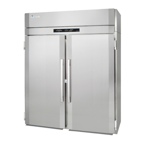
Fisherbrand Isotemp 333773H01 User manual

Fisherbrand™Isotemp™
General Purpose Freezer
Installation and Operation
333773H01• Revision C• 05/19/2023

2
IMPORTANT Read this instruction manual. Failure to follow the instructions in this
manual can result in damage to the unit, injury to operating personnel and poor
equipment performance.
CAUTION All internal adjustments and maintenance must be performed by qualified
service personnel.
Material in this manual is for informational purposes only. The contents and the product
it describes are subject to change without notice. The Fisher Scientific channel makes
no representations or warranties with respect to this manual. In no event shall the Fisher
Scientific brand be held liable for any damages, direct or incidental, arising from or
related to the use of this manual.
© 2023 Fisher Scientific LLC. All rights reserved.

Contents
Model 5
SafetyInformation 6
Alert Signals 6
IntendedUse 8
GeneralPurposeFreezer 9
ProductSpecification 9
UnpackingandInspection 10
Unpacking 10
Visible Loss or Damage 10
Concealed Loss or Damage 10
OperatingConditions 11
Installation 12
SelectingaLocation 12
LevelingtheUnit 12
ElectricalConnection 12
Be Advised 13
Operation 14
Start-UpProcedure 15
Control Panel FBV18FPSA Operations 15
Max and Min Temperature Memorization 16
MainFunctions 16
Restart Procedure 17
HowtoSaveEnergy 17
SafetyTips 17
ControllerParameters 18

4
Maintenance 20
Defrosting 20
CleaningtheUnit 20
Cleaning Interior / Exterior / Door Gaskets 20
Cleaning the Condenser 20
Doors/Hinges 21
GasketMaintenance 21
Transportation and Storage 21
Troubleshooting 22
Alarmssignals 22
Other Messages 22
General 23
WiringDiagram 24
EndofLifeCare 25
Warranty 26
RegulatoryCompliance 27
ProductSafety 27
ElectromagneticCompatibility 27
ContactInformation 29

5
Model
The table below show the units covered in this operation and installation manual by model number.
Table 1. Applicable Model
Freezer
FBV18FPSA

6
It is your responsibility to understand the proper function
and operational characteristics of the unit. This instruction
manual should be thoroughly read and all operators
must be trained before attempting to place these units in
service. Awareness of the stated cautions and warnings,
and compliance with recommended operating parameters
together with maintenance requirements are important for
safe and satisfactory operation. The units should be used
for its intended application, alterations or modifications will
void the Warranty.
This product is not intended, nor can they be used, as
a sterile or patient connected device. In addition, these
units are not designed for use in Class I, II or III locations
as defined by the US National Electrical Code, unless
otherwise noted.
Alert Signals
Safety Alert: Important operating
instructions. To reduce the risk of injury
or poor performance of the unit. Read the
user manual before putting the equipment
into operation.
WARNING: Indicates an immediately
hazardous situation, which if not avoided,
will result in death or serious injury.
CAUTION: Indicates an immediately
hazardous situation, which if not avoided,
may result in minor to moderate injury.
WARNING: Avoid contact with cold freezer
surfaces potential for cold burns or skin
sticking to cold surfaces.
WARNING: Use of this symbol involves risk
of electric shock.
Note: Notes alert you to pertinent facts and
conditions
Safety Information
Do not modify or use power supplies
other than OEM equipment. Connection
of the power supply may require a
properly grounded receptacle. Potential
for electrical shock or equipment damage
exists if precautions are not followed.
DANGER RISK OF CHILD ENTRAPMENT
Before you throw away your old freezer:
• Take o doors.
• Leave the shelves in the place so that
children may not easily climb inside.
WARNING: Do not use electrical
appliances inside the cabinet of the
appliance, unless they are of the type
recommend by the manufacturer.
Note: Component parts shall be replaced
with like components, so as to minimize
the risk of possible ignition due to incorrect
parts or improper service.
WARNING: If the equipment is used in a
manner not specified by the manufacturer,
the protection provided by the equipment
may be impaired.
WARNING: Units are charged with
hydrocarbon refrigerant (R290). Only
qualified service personnel should service
this unit.
WARNING: Risk of fire or explosion.
Flammable refrigerant used. To be repaired
only by trained service personnel. Do not
puncture refrigerant tubing.
WARNING: No equipment that uses an
open flame should be placed inside the
freezer.This will harm the unit, hamper
functionality and compromise your safety.
WARNING: Risk of fire or explosion.
Flammable refrigerant used. Do not use
mechanical devices to defrost the unit.

7
WARNING: This product can expose you
to chemicals including DI (2-ETHYLHEXYL)
PHTHALATE (DEHP), which is known to the
State of California to cause cancer and birth
defects or other reproductive harm. For
more information go to
www.P65Warnings.ca.gov
WARNING: Risk of fire.This unit is not for
storage of flammable materials.
WARNING: Risk of fire. No equipment that
uses an open flame should be placed inside
the unit. This will harm the unit, hamper
functionality and compromise your safety.
WARNING: Risk of shock. Disconnect unit
from all power sources before cleaning,
troubleshooting, or performing other
maintenance on the product or its controls.
CAUTION: Risk of fire or explosion.
Dispose of property in accordance with
federal or local regulations. Flammable
refrigerant used.
CAUTION: Adjusting Programmable
parameters can result in system failure,
have an impact on how well the system
works and performs, and void the warranty.
The appliance use flammable insulation
blowing gas C5H10. The disposal of the
appliance shall be in accordance with the
regulations of local authorities.
If the supply cord is damaged, it must be
replaced by the manufacturer, It’s service
agent or similarly qualified persons in order
to avoid a hazard.
WARNING: Keep ventilation openings, in
the appliance enclosure or in the built-in
structure, clear of obstruction.

8
The General Purpose Freezer described in this manual is
for professional use only.
These products are intended for laboratory use in storing
samples between -22°C and -10°C.
These units are not considered as medical devices and
have therefore not been registered with a medical device
regulatory body (e.g. FDA): that is, these have not been
evaluated for the storage of samples for diagnostic use or
for samples to be re-introduced to the body.
Note: Do not store corrosive materials in these units. Any
damage which occurs due to storage of corrosives will not
be covered under warranty claims.
Follow site protocols to identify materials of corrosive
nature.
Intended Use

9
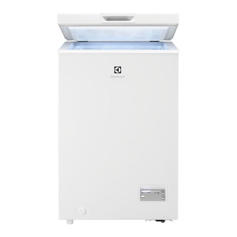
These are General Purpose Freezer units.
Model: FBV18FPSA - 18 Cu.ft
30.6” Wide, freezer
Features:
• Color: White
• Defrost Type: Manual
• Interior Light: No
• Control Type: Electronic
• Defrost Drain: No
• Shelves: 6 Non-adjustable
• Leveling Legs: 2
• Convertible: No
• Default Settings: Freezer -20°C Set
Product Specification
FBV18FPSA
Exterior Dimensions
H x W x D inches (cm)
74.6 x 30.6x 27.8Inches
(189.5x 77.7 x 70.5 cm)
Net Weight lbs. (kg) 216.05 lbs (98 kg)
Shipping Weight lbs. (kg) 240.3 lbs (109 kg)
Freezer Set Point Adjustable Range -22°C to -10°C
Electrical Characteristics Volts / Hz, Amps 115 V / 60 Hz, 5.5 A
Maximum allowed load on the shelves lbs (kg) 22.04 lbs (10 kg)
Note: Amps listed are at normal run mode, starting amps may be higher.
General Purpose Freezer

10
CAUTION: DO NOT REMOVE, under any
circumstance, the grounding prongs from
the 3-prong power cord supplied with all
unit
CAUTION: DO NOT USE electrical
extension cords that may result in voltage
loss and possible hazardous operation.
Unpacking
This should be inspected upon delivery. When received,
carefully examine for any shipping damage before
unpacking. If damage is discovered, the delivering carrier
should both specify and sign for the damage on your copy
of the delivery receipt.
Visible Loss or Damage
Note any external evidence of loss or damage on the
freight bill, or express receipt, and have it signed by the
carrier’s agent. Failure to adequately describe such external
evidence of loss or damage may result in the carrier’s
refusing to honor your damage claim. The form required to
file such a claim will be supplied by the carrier.
IMPORTANT: Failure to request an inspection of damage
within a few days after receipt of shipment absolves the
carrier from any liability for damage.You must call for a
damage inspection promptly.
Concealed Loss or Damage
Concealed loss or damage refers to loss or damage, which
does not become apparent until the merchandise has been
unpacked and inspected. If either occur, make a written
request for the carrier’s agent within 10 days of the delivery
date; then file a claim with the carrier since the damage is
the carrier’s responsibility.
Unpacking and Inspection
If you follow the above instructions carefully, we will
guarantee our support of your claim to be compensated for
loss from concealed damage.
DO NOT, FOR ANY REASON RETURN THIS UNIT
WITHOUT FIRST OBTAINING AUTHORIZATION.
Location of Parts
Location of Parts
Location of Parts
Figure 1. FBV18FPSA Model
Note: Figure 1 is only for reference. The actual
configuration will depend on the physical product or
statement by the distributor.

11
Operating Conditions
The unit described in this manual is classified for use as
stationary equipment in a Pollution Degree 2 and Over
voltage Category II environment.
This unit is designed to operate under the following
environmental conditions:
• Indoor use
• Altitude up to 2,000 m (6512 feet)
• Maximum relative humidity 65%, non-condensing
• Temperatures: 59°F to 90°F (15°C to 32°C)
• Main supply voltage fluctuations should not exceed by
-6% to +10% of the nominal voltage.

12
Installation
Selecting a Location
Choose a location for the FBV18FPSA that provides a
clearance of 12” at the top, 2” at the rear and 2” on each
side.
Appropriate electrical power must be available. Attach the
freezer to the facility’s electrical supply as directed by the
National Electrical Code.
Installation Instructions
Remove all packing materials, including the bottom
cushions, foam pads, and tape inside the unit. Tear o all
protective film on the doors and on the freezer body.
• Place the unit in a well ventilated place, on flat sturdy
ground.
• Avoid locating the unit in moist or humid areas. Excess
moisture in the air may cause frost to form quickly on the
evaporator and cabinet, requiring frequent defrosting.
• Locate the unit away from direct sunlight and other heat
sources. Direct sunlight may aect the performance of
the unit.
Let the freezer stand upright for approximately 24 hours
before connecting it to power. This reduces the possibility
of a malfunction in the cooling system from improper
handling during transportation.
While moving the unit, DO NOT tilt it beyond 45° from
upright.
Leveling the Unit
It’s very important for the freezer to be level. If the freezer is
not leveled during installation, the doors may not close or
seal properly, causing cooling, frost or moisture problems.
To level your freezer, rotate the leveling feet clockwise
(to raise) or counter-clockwise (to lower).
Note: Have someone push against the top of the freezer to
help take some weight o the leveling foot, making it easier
to adjust.
Electrical Connection
Determine the total amount of current presently being
used by other apparatus connected to the circuit that will
be used by this freezer. It is critical that this added current
demand and other equipment on this circuit not exceed the
rating of the fuse or circuit breaker in use.
The frequency and nominal voltage requirements for the
unit are specified on the data plate. Supply this unit with an
electrical source that meets these requirements only. Low
line voltage is often the cause of service complaints. With
the unit running, check that the line voltage is within
-6% to +10% of that specified on the data plate.
CAUTION: Be sure the voltage supplied to
the freezer is equal to that specified on the
data plate.
WARNING: For personal safety, this unit
must be properly grounded before use.
General Purpose units must be connected to a grounded
outlet matching the nameplate and / or the information
furnished in this manual. If you are not sure about the
outlet, you should contact a qualified electrician for
assistance.
The Unit should always be connected to a dedicated power
source.
WARNING: DO NOT REMOVE, under any
circumstance, the grounding prongs from
the 3-prong power cord supplied with all
units.
WARNING: DO NOT USE electrical
extension cords, it may result in voltage
loss and possible hazardous operation.

13
Be Advised
WARNING: Storage by user of any
materials in the product that may cause
a deterioration of the product shall be
deemed to constitute abnormal and
improper usage of the product for
purposes of this warranty.
WARNING: Before connecting the
final power supply, check the electrical
characteristics of the unit nameplate to
see that it is in agreement with the power
supplied. In addition, power should be
wired to the unit according to the electrical
schematic and all applicable codes. Only
qualified electricians should work on the
electrical portion of any unit installation.

14
CAUTION: Do not use in the presence
of flammable or combustible materials or
explosive gases. Fire or explosion could
result, causing death or severe injury.
Follow site protocols for loading and unloading samples.
Overloading the unit forces the compressor to run longer.
Wipe containers dry before placing items in the unit. This
cuts down on frost build-up inside the unit.
The unit storage shelves should not be lined with aluminum
foil, wax paper or paper toweling. Liners interfere with cold
air circulation, making the unit less ecient.
Organize and label to reduce door openings and extended
searches. Remove as many items as needed at one time,
and close the door as soon as possible.
Before Using the Unit
1. Keep the unit upright for 24 hours before connecting to
the power supply.
2. Connect the unit to a power supply, and let the unit run
for 2-3 hours.
Note: If the ambient temperature of the room is higher
than normal (starting the machine in the summertime, for
example), it may take up to 4 hours to start using the unit.
Operation

15
Control Panel FBV18FPSA
Operations
Once the unit is turned on, the display screen will display.
The unit will run on Setting automatically
Front Panel Command
To display target set point; in programming
mode it selects a parameter or confirm an
operation.
(UP) To view the latest alarm occurrence;
in programming mode it browses the
parameter codes or increases the display
value.
(DOWN) To view the latest alarm
occurrence; in programming mode
it browses the parameter codes or
decreases the display value.
To switch the instrument on and o, if
onF=oFF.
Not enabled.
Not enabled.
Start-Up Procedure
Key Combinations:
+
To lock & unlock the keyboard.
+To enter in programming model
+To return to the room temperature
display
Function of LED:
LED MODE FUNCTION
ON Compressor enabled
Flashing Anti-short cycle delay enabled
ON Defrost enabled
ON An alarm is occurring
ON Continuous cycle is running
°C/°F ON Measurement unit
°C/°F Flashing Programming phase

16
Max and Min Temperature
Memorization
How to See the Min Temperature
1. Press and release the key.
2. The “Lo” message will be displayed followed by the
minimum temperature recorded.
3. By pressing the key again or by waiting 5s the
normal display will be restored.
How to See the Max Temperature
1. Press and release the key.
2. The “Hi” message will be displayed followed by the
maximum temperature recorded.
3. By pressing the key again or by waiting 5s the
normal display will be restored.
How to Reset the Max and Min
Temperature Recorded
1. Hold press the SET key for more than 3s, while the
max. or min temperature is displayed. (rSt message will
be displayed).
2. To confirm the operation the “rSt” message starts
blinking and the normal temperature will be displayed.
Main Functions
How to See the Setpoint
1. Push and immediately release the
SET key: the display will show the
Set point value.
2. Push and immediately release the
SET key or wait for 5 sec to display
the probe value again.
How to Change the Setpoint
1. Push the SET key more than 2 sec to change the Set
point value.
2. The value of the set point will be displayed and the
LED will start blinking.
3. To change the Set value push the +arrows within
10 sec.
4. To save the new set point value, push the SET key
again or wait for 10 sec.
How to Lock the Keyboard
1. Hold the and keys for
more than 3s.
2. The “POF” message will be
displayed and the keyboard will
be locked. At this point, it will be
possible only to see the set point or
the Max or Min temperature stored.
3. If a key is pressed more than 3s the
”POF” message will be displayed.

17
Safety Tips
CAUTION: After a unit is in operation, do
not touch the cold surfaces, particularly
when hands are damp. Skin may adhere to
the cold surfaces.
WARNING: We recommend handling
samples by wearing gloves to avoid frost
bite.
WARNING: Never disconnect your unit by
pulling the power cord. Always grip the plug
securely and pull straight out from the outlet
.
WARNING: Do not use a power cord that
shows cracks or abrasions. Have a qualified
electrician repair or replace damaged cords
immediately.
How to Unlock the Keyboard
Hold the and keys together for more than 3s, till
the “POF” message is displayed.
The ON/OFF Function
With “onF = oFF”, pushing the
ON/OFF key, the instrument is
switched o. The “OFF” message is
displayed. In this configuration, the
regulation is disabled. To switch the
instrument on, push again the ON/OFF
key.
WARNING: Loads connected to the
normally closed contacts of the relays
are always supplied and under voltage,
even if the instrument is in stand by
mode.
Restart Procedure
If unit is unplugged or turned o, allow 5 minutes before
restarting or plugging it back in.
How to Save Energy
Be sure to follow location suggestions as mentioned in the
Installation.
• Wipe moisture from glassware or other materials before
placing them in a unit.
• Don’t overcrowd the unit. Too many items can increase
electrical energy demand in order to keep everything
cool.
• Close the door as soon as possible in hot, humid
weather.
• Make certain that the door is closed tightly.
• Keep containers covered, when possible, to reduce
moisture buildup.
• Set operating temperature no colder than necessary for
the items being refrigerated.

18
The main function settings are meant for user
customization. The programmable controller settings
are provided only for information. Adjustments to
Programmable parameter settings may cause system
failure, impact how well the system runs and performs,
and void the warranty.
How to Change a Parameter Value
To change the parameter’s value operate as follows:
1. Enter the Programming mode by pressing the
Set + keys for 3s (the “°C” or “°F” LED starts
blinking).
2. Select the required parameter. Press the “SET” key
to display its value.
3. Use “UP” or “DOWN” to change its value.
4. Press “SET” to store the new value and move to the
following parameter.
To exit: Press SET + UP or wait 15s without pressing a
key.
Note: The set value is stored even when the procedure is
exited by waiting the time-out to expire.
The Hidden Menu
The hidden menu Includes all the parameters of the
instrument.
How to Enter the Hidden Menu
1. Enter the Programming mode by pressing the
Set + keys for 3s (the “°C” or “°F” LED starts
blinking).
2. Released the keys, then push again the Set +
keys for more than 7s. The Pr2 label will be displayed
immediately followed from the HY parameter.
Now you are in the Hidden Menu
3. Select the required parameter.
4. Press the “SET” key to display its value.
5. Use or to change its value.
6. Press “SET” to store the new value and move
Controller Parameters
to the following parameter.
To exit: Press SET + UP or wait 15s without pressing a key.
Note: If none parameter is present in Pr1, after 3s the “noP”
message is displayed. Keep the keys pushed till the Pr2
message is displayed.
Note: The set value is stored even when the procedure is
exited by waiting the time-out to expire.
How to Move a Parameter from the Hidden menu to the
First Level and Vice versa.
Each parameter present in the HIDDEN MENU can be
removed or put into “THE FIRST LEVEL” (user level) by
pressing Set + .
In HIDDEN MENU when a parameter is present in First Level
the decimal point is on.
The following is a list of the unit’s suggested settings for the
parameters:
Table 2. Controller Parameters
Label Name Recommended
Set Value
* Set Set point -20
Hy Dierential 3
LS Minimum set point -22
US Maximum set point -10
Ot Thermostat probe calibration 0.0
P2P Evaporator probe presence n
OE Evaporator probe calibration 0.0
P3P Third probe presence n
O3 Third probe calibration 0
P4P Fourth probe presence n
O4 Fourth probe calibration 0
OdS Outputs delay at start up 0
AC Anti-short cycle delay 5
CCt Continuous cycle duration 0
CCS Set point for continuous cycle -20

19
Table 2. Controller Parameters
Label Name Recommended Set
Value
COn Compressor ON time
with faulty probe
10
COF Compressor OFF time
with faulty probe
10
CH Kind of Action cL
CF Temperature
measurement unit
°C
rES Resolution dE
dLy Display temperature
delay
5
dtE Defrost termination
temperature
5
IdF Interval between defrost
cycles
24
MdF (Maximum) length for
defrost
0
dSd Start defrost delay
dFd Displaying during defrost SET
dAd MAX display delay after
defrost
30
ALc Temperat. alarms
configuration
rE
ALU MAXIMUM temperature
alarm set
90
ALL Minimum temperature
alarm
90
AFH Dierential for temperat.
alarm recovery
1
ALd Temperature alarm delay 255
dAo Delay of temperature
alarm at start up
1
AP2 Probe for temperat.
alarm of condenser
np
AL2 Condenser for Low
temperat. Alarm
-40
AU2 Condenser for high
temperat. Alarm
144
Table 2. Controller Parameters
Label Name Recommended
Set Value
AH2 Dier. for condenser temp.
alar. Recovery
5
Ad2 Condenser temperature
alarm delay
0
dA2 Delay of cond. temper.
alarm at start up
0
bLL Compr. o for cond. low
temp. alarm
n
AC2 Compr. o for cond. high
temp. alarm
Y
i1P Digital input polarity CL
i1F Digital input configuration dor
did Digital input alarm delay 15
nPS Number of activation of
pressure switch
15
odc Compress status when
open door
no
rrd Regulation restart with
door open alarm
Y
HES Dierential for energy
saving
0
PbC Kind of probe ntc
Adr Serial address 1
onF on/o key enabling oFF
dP1 Room probe display ---
dP2 Evaporator probe display ---
dP3 Third probe display ---
dP4 Fourth probe display ---
rSE Real set point value ---
rEL Software release ---
Ptb Map code ---
Note: Main function settings are represented by (*) and are
intended for user customization.

20
Maintenance
Unit should be cleaned at least once a year following
instructions below.
CAUTION: When servicing the unit,
disconnect from the electrical power
source.
CAUTION: Refer servicing to qualified
personnel
Note: Follow site protocols for cleaning the unit.
Defrosting
Note: Do not use mechanical devices or other means
to accelerate the defrosting process, other than those
recommended by the manufacturer.
1. Remove all contents from freezer.
2. Turn o the unit at the controller or the power supply.
3. Place towels at the bottom of freezer to absorb water.
4. Defrosting may take up to several hours. To defrost
faster:
• Leave door open.
• Place pans of hot water on frost shelves.
• Wipe with warm towel or sponge.
CAUTION: Never use a knife or other metal
object to remove frost and/or ice.
Cleaning the Unit
Before beginning cleaning unit follow these instruction
listed below:
• Disconnect power cord from its outlet.
• The unit designs permit easy cleaning. Remember to
wear protective gloves to prevent frost bite, especially
when removing items from freezer units.
• Do not use abrasive scouring powders, waxes, solvents,
furniture polish, undiluted detergents or cleansers
containing petroleum products on the surfaces of units.
Cleaning Interior / Exterior /
Door Gaskets
The interior, exterior and the door gasket can be cleaned
using neutral cleaning agent and lukewarm water with a
soft, clean cloth. If this isn’t sucient, try ammonia and
water or a nonabrasive liquid cleaner.
Do not use an abrasive cleaner because it will scratch the
plastic and can damage the shelves and gaskets.
Rinse with clean water and dry thoroughly before
reconnecting and turning on the unit.
The cabinet interior should be cleaned frequently. Any
spilled liquid should be wiped o immediately since stains
resulting from some spills could be permanent if not quickly
removed. The most convenient time to clean the interior is
after defrosting.
CAUTION: Solutions used to clean coils
or neutralize bacteria growth must not be
corrosive to metals (enamel-coated steel)
and materials used in the maintenance of
this equipment-damage can result: use a
soft cloth and warm water to clean.
Cleaning the Condenser
With forced-fan vented units, remove the screws that
mount the grill to the unit. This will expose condenser for
cleaning.
These surfaces may be warm to the touch. The condenser
coil requires regular cleaning, and is recommended every
90 days. In some instances, you may find that there is a
large amount of debris and dust or grease accumulated
prior to the 90 day time frame. In these cases the
condenser coil should be cleaned every 30 days. If the
build up on the coil consists of only light dust and debris,
the condenser coil can be cleaned with a simple brush.
Heavier dust build-up may require a vacuum or even
compressed air to blow through the condenser coil.
Table of contents
Languages:
