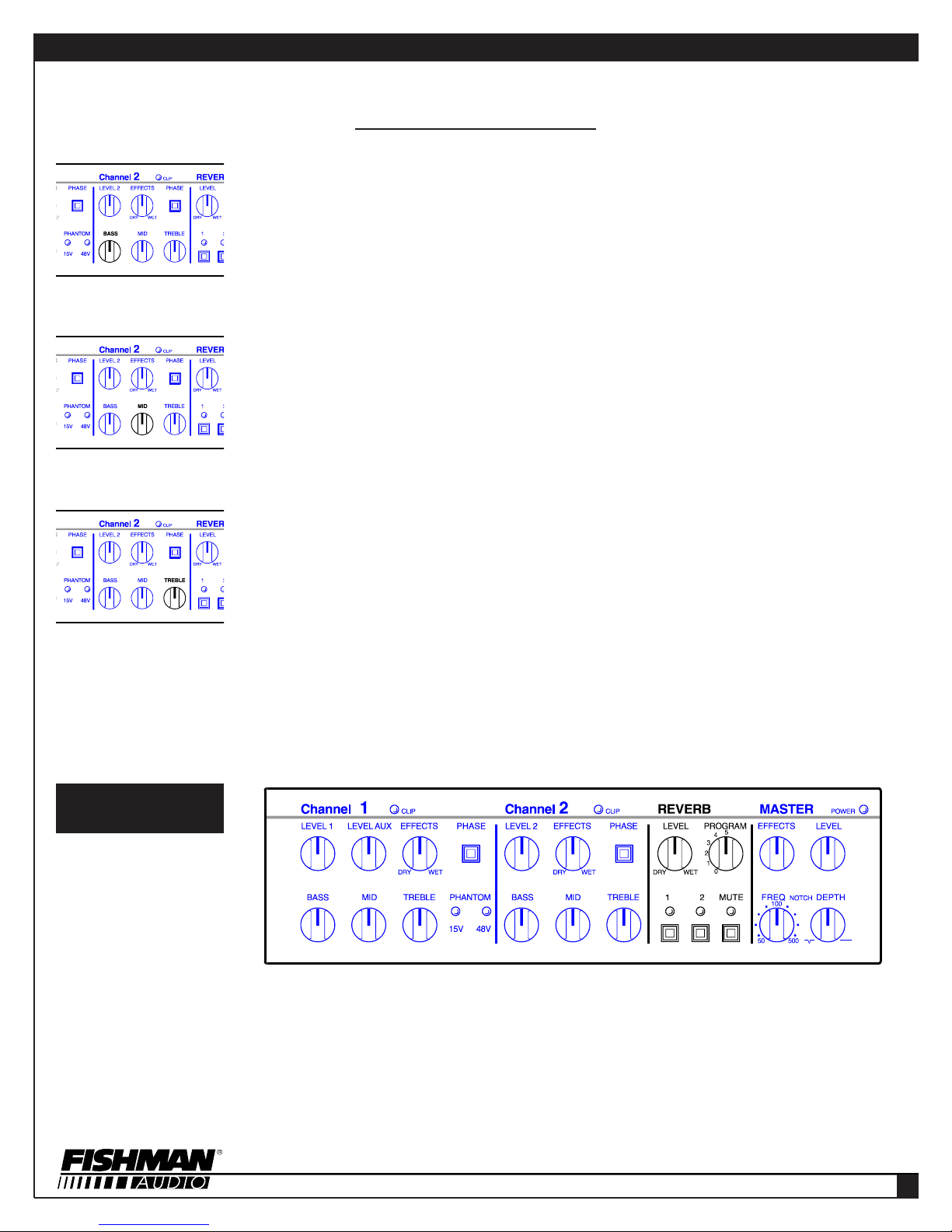
FRONT PANEL - CHANNEL 2 Continued
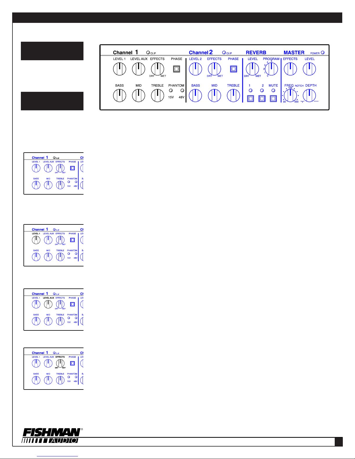
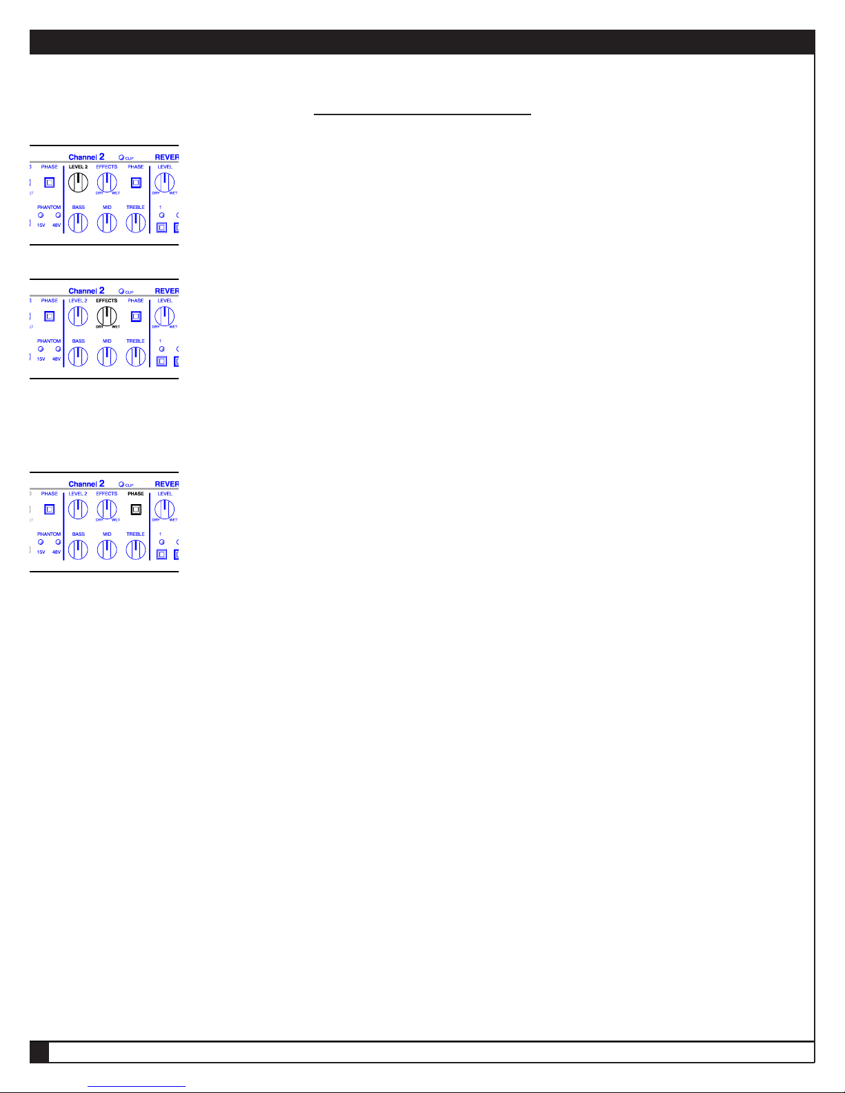
LEVEL 2
This knob sets the volume of the signal coming from your instrument to the Channel 2 preamp section of the Acoustic Performer
Pro. It also adjusts Channel 2’s volume relative to the Auxiliary Input’s level, and the level of Channel 1.
NOTE: Before you adjust Level 2, check the Master section’s Level control. If it’s set all the way down, no sound will come out of
the amp, regardless of how you adjust Level 2. Conversely, if the Master Level is set extra-high, then turning up Level 2 can result
in hair-raising loudness. Think of Level 2 and the Master section’s Level as operating in tandem.
EFFECTS
When you place an external signal processor (also called an effect, stomp box, etc.) into Channel 2’s Effects Loop, you can blend
the effect with your acoustic instrument’s sound. Fishman designed the Effects Loop to run in parallel with your main signal. Why?
Most Effects Loops require sending the entire signal through the Effects Loop, thereby making it vulnerable to the introduction of
extraneous noise, plus it can noticeably degrade the signal, especially if the signal processor isn’t as clean as the Acoustic
Performer Pro, or its frequency range is limited. The Acoustic Performer Pro’s strategy ensures a solid, dynamic, straight sound and
then blends the effect much the way a professional mixing console approaches effects blending.
NOTE: For the best sound quality and lowest noise, adjust the signal processor’s mix control (if it has one) so that its output con-
tains only a “wet” (effect-enhanced) signal.
PHASE
When a signal is out of phase with another signal, it can cause cancellation, which (as its name implies) results in something miss-
ing. The opposite is true when two signals are in phase; the combined signals can be solid or absolutely overpowering, depending
on the sounds and how much “in phase” they are. Using the phase relationship between two sounds can be a powerful tool for fight-
ing feedback or making multiple sound sources (such as a pickup and a built-in microphone) sound better together.
The Phase switch can accomplish a couple of different things. If you are using an instrument equipped with only one pickup or inter-
nal microphone, it can invert the signal’s phase, which can, in some cases, be a remedy for feedback. If your instrument has a built-
in mic as well as a pickup, one of the signals may be out of phase in relation to the other, so employing the Phase switch on one
channel of the Acoustic Performer Pro corrects that, providing a stronger signal, often with better tone.
NOTE: When a pickup and an internal mic are used, try using the phase switches on both channels to check for correct phase rela-
tionships between the two sound sources. Also, if your instrument has only one pickup or microphone, try the Phase switch in both
its in and out positions, to be sure the best sound is being produced.
1
FOLLOW THIS PROCEDURE TO MAKE BEST USE OF THE PHASE SWITCHES
If you have a microphone in your setup, it is best to begin getting a sound from that.
With the Master Level at 3/4 of its maximum volume, bring the microphone’s volume up to the desired level. In the event that the
mic begins to feed back, adjust the volume lower or use the Bass, Mid, or Treble EQ controls to eliminate the feedback.
Determine the location onstage where you are going to play, and set the phase switch on the mic channel to the sound that is most
pleasing. Since the characteristics of microphones and their placement play a big part in the sound achieved, this would also be a
good time to adjust or aim the mic in your instrument to get the most appropriate sound. Keep in mind that given the nature of
acoustic instruments and how they interact with amplifiers, once the phase is set, if you move more than 5 or 6 feet from your play-
ing location, the phase will reverse itself 180 degrees.
With the microphone volume on, adjust the transducer’s level until it is approximately equal in volume to the microphone. Next, flip
the transducer’s Phase switch and you will immediately hear what is correct. If it’s the incorrect phase relationship, you will get a
tremendous amount of bass loss because the bass frequencies cancel.
After taking these steps to determine the correct phase settings, make note of their relative positions. These settings between the
mic and transducer will remain the same from performance to performance, with the exception that each may need to be reversed
together in some instances. In other words, if you determine that the phase of the mic is in and the phase of the pickup is out, there
may be a case where you will need to set the mic to out and the pickup to in.
ACOUSTIC PERFORMER PRO OWNER'S MANUAL
➥
ACOUSTIC PERFORMER PRO
9