FITOP M Series User manual

M-series OPERATIONS MANUAL

WIRE ROPE HOIST INSTRUCTION MANUAL
CONTENT
Ⅰ.FOREWARD
1-1 Dear Customers
1-2 Customers’ responsibility
1-3 Disclaimer
1
1
1
Ⅱ.NOTES BEFORE INSTALLATION
2-1 General Examination
2-2 Insulation
2-3 Rail
2-4 Notes of installation on power feeding system
2-5 Distribution of the control panel (electricals)
2-6 Voltage
2
2
2
2
2
3
Ⅲ.INSTALLATION OF HOIST
3-1 Mono-rail
3-2 Double-rail
3-3 Lifting hoist (Cargo elevator)
3
3
3
Ⅳ.TESTING
4-1 Confirmation before running
4-2 Confirmation before un-loading running
4-3 Confirmation before full-loading running
4-4 Confirmation after testing your hoist
4-5 Confirmation of safety device
4
4
4
4
4
Ⅴ.IMPROPER OPERATIONS
5-1 Correct Operation
5-2 Prohibitions
6
6
Ⅵ.MAINTENANCE
6-1 Notes for maintenance
6-2 Limitations of Use
6-3 Items examined daily
6-4 Items examined monthly
6-5 Items examined quarterly
6-6 Items examined yearly
6-7 Structure & Mechanism
6-8 Electrical device
10
10
13
13
13
14
15
17
Ⅶ.TROUBLESHOOTING AND MAINTENANCE
7-1 Notes of Maintenance
7-2 Mechanism
18
18

I.FOREWARD
1-1. Dear Customers:
Now you are the owner of “FiTOP” M-series Electric Wire Rope Hoist, and we are confident
that it will meet your expectation. The product is a best tool of automation for lifting and
carrying purposes. It is produced under careful design, manufacturing, and strict quality
assurance. Before leaving the factory, every set is tested to meet CNS regulation for
domestic and overseas markets. It is surely safe!
However, in order to perform it effectively, this operations manual is compiled by FiTOP to
let you fully understand the operations and maintenance. Please read it carefully before
operation, and the manual will serve you with clear instructions since your growth in
business and prosperities are our greatest achievements!
1-2. Customers’ responsibility
For safety and durability, please follow the contents which include daily and periodic
guidance for maintenance. You are required to follow the advices as the following:
1-2-1. Please follow the manual to operate the equipment
1-2-2. Please follow the contents as your daily and periodic maintenance. If you need to
solve technical or maintenance issues, kindly let your regional distributor be
acknowledged
1-2-3. Please use the original spares provided by FiTOP
1-2-4. If the hoist has problem, please inform your regional distributors to deal with it at
the same time
1-2-5. If you have sold out the equipment to other end-users, please let your regional
distributor be advised about it
1-2-6. Kindly obey the official regulations with the requirements specified by your central
and state governments
1-2-7. For safety, please educate your employees before they start using the equipment
and hire a qualified person as your staff who has obtained a certified permission in
operating above 3-ton-capacity hoist
1-3. Disclaimer
If the following behaviours caused either direct or indirect damage, FiTOP will NOT take any
responsibility:
1-3-1. Wrong operations and incorrect use of the hoist
1-3-2. Change and adjust from the original design on the hoist
1-3-3. If NOT using the spares or grease provided by FiTOP
1-3-4. Kindly stop using the equipment if NOT following the instructions on the daily and
regular guidance for maintenance

2
II.NOTES BEFORE INSTALLATION
2-1. General Inspection
2-1-1. Inspect IF the specifications are in compliance with the requirements
2-1-2. Inspect IF the hoist is damaged during the process of carrying
2-1-3. Inspect IF all parts on the following are enclosed:
(1) Button switch
(2) Fuse
(3) Structural drawing
(4) Circuit diagram
(5) Wire rope
(6) Other specific demands
2-2. Insulation
Inspect the resistance of insulation system: Using 500V high-impedance metre to measure
if the resistance of each individual part is above 1ΜΩ
2-3. Rail
2-3-1. A device in condition of rest should be set on the rail
2-3-2. The gap between each rail connection should NOT exceed 0.8 cm
2-3-3. The installation of rail should be complied with government regulations and be sure
to keep the level at transversal and horizontal directions to avoid instability during
operations
2-4. Notes of installation on power feeding system
Type of safety rail:
(1) The fixing clamp should be in the same line and level
(2) The welding of towing-arm should be formed as squared-iron stick
(3) Fix-squared- bar should be in parallel with the surface of safety rail, and the
distance is 70+10 mm
2-5. Distribution of the control panel (electricals):
For standard specifications, please refer to circuit diagram: Fig. 1, 2, 3, 4, and 5; for others,
kindly refer to the circuit diagram inside the box of control panel.
2-6 Voltage:
If the voltage is less than 5%, the motor will not reach the operating voltage; thus, before
using the hoist, kindly check if the voltage is normal or not.
III.INSTALLATION OF HOIST
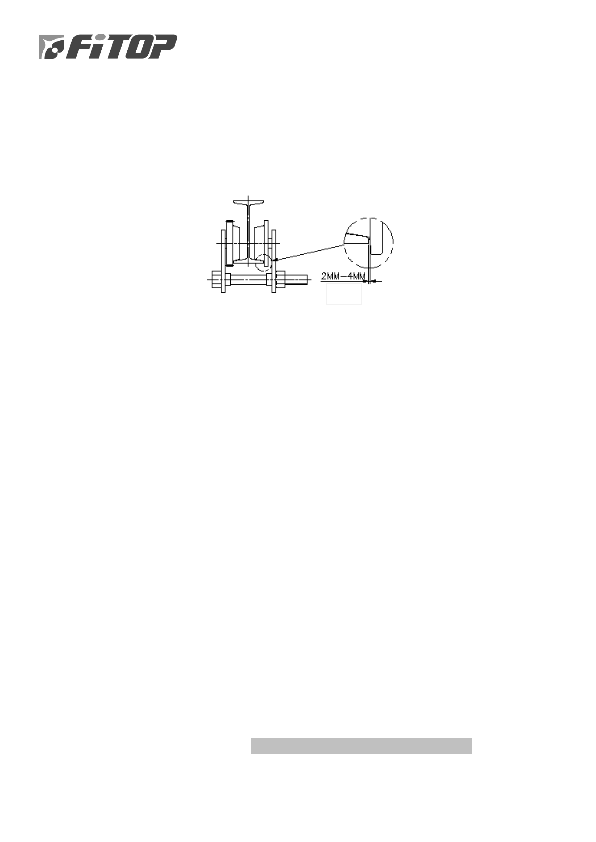
3-1. Mono-rail
3-1-1. The width of I / H-beam girder should be >= (the base width of trolley
wheel + 2 to 4 mm gap) shown as the following:
3-1-2. When one end of girder is opened, the hoist and trolley could be combined and
installed from the opening end
3-1-3. When both ends of girder are closed, or the end of girder cannot be opened to
cause hoist to fail entering-in, please release the trolley plates and install it.
3-2. Double-rail
After hoist and trolley are combined, please set it on the traversing rail directly.
REMARK: There is an eccentricity self-regulation device for the axle of double-rail hoist,
so the movement of the trolley wheel can be balanced on the rail. When main hoist has
no loading, the four trolley wheels may not touch to the rail simultaneously; however,
this circumstance will not be happened after loading.
3-3. Lifting hoist (Cargo elevator)
Lifting cabin should be elevated to the top-end. Kindly move the hoist in order to keep
the centre of gravity of hook is the same as the vertical line of lifting box; then, please fix
the hoist horizontally and correctly.
IV.TESTING
4-1. Confirmation before running
4-1-1. The auxiliary supporting line of the control pendent should be tied firmly and
correctly, to avoid the cable being deformed under force
4-1-2. The position of control pendent should be at 1 metre distance from the floor
4-1-3 A stable voltage is normally (R, S, T,) 3-phase averaged range: 5%~+5%; if the voltage
is insufficient, will cause the motor burn up
Gap

4
4-2. Confirmation before un-load running
4-2-1. Testing the control pendent:
Please press the button “UP” first when testing; do NOT press the button “DOWN”
first. After pressing “UP”, the hook will be lifted up, indicating that it has no
problem; if the hook moves downward, the power connection of hoist is NOT
correct (error phase sequence). As a result, please change two wires of R, S, T,
alternatively, and repeat the above steps until this problem has been solved. If the
hoist was used with a wrong wire-connection (error phase sequence), the limit
switch will be INVALID and it may cause the wire-rope BROKEN or severe damage
of the hoist accidents; therefore, be careful and pay attention to this condition
4-2-2. Press the button switch to keep the hook lifting up:
When hook reaches the position of UP LIMIT, the limit-switch will start to stop the
hook automatically; please press “DOWN” to make sure if the hook is moved
downward
4-2-3. To let the hoist load 100 kg-200 kg loading and move full-distance up and down,
please check the following when moving:
(1) Is the rail proper?
(2) Is any interference for cable?
(3) Is the space enough between the hook and building?
(4) Could the hoist touch the building?
4-3. Confirmation before full-load running
4-3-1. First, please test its lifting up and down movements, and check if the sliding is
appropriate or not after braking?
4-3-2. Is it stable or not? When the hoist is moving?
4-3-3. When hoist is moving, test the voltage of trolley. The voltage should NOT exceed 7%
of the voltage of motor that shows on the nameplate of motor
4-4. Confirmation after testing your hoist
4-4-1. After testing the hoist, please check the rope press block on the drum, if it is
loosened or not?
4-4-2. Check the traversing and runway rail, if they are loosened or not?
4-4-3. Check the temperature of motors, if they are normal or not?
4-5. Confirmation of safety device
4-5-1. Upper- and lower-limit-switch:
Use the spiral limit-switch to ensure that the wire rope would stop when it reaches
upper- and lower-limit during operation
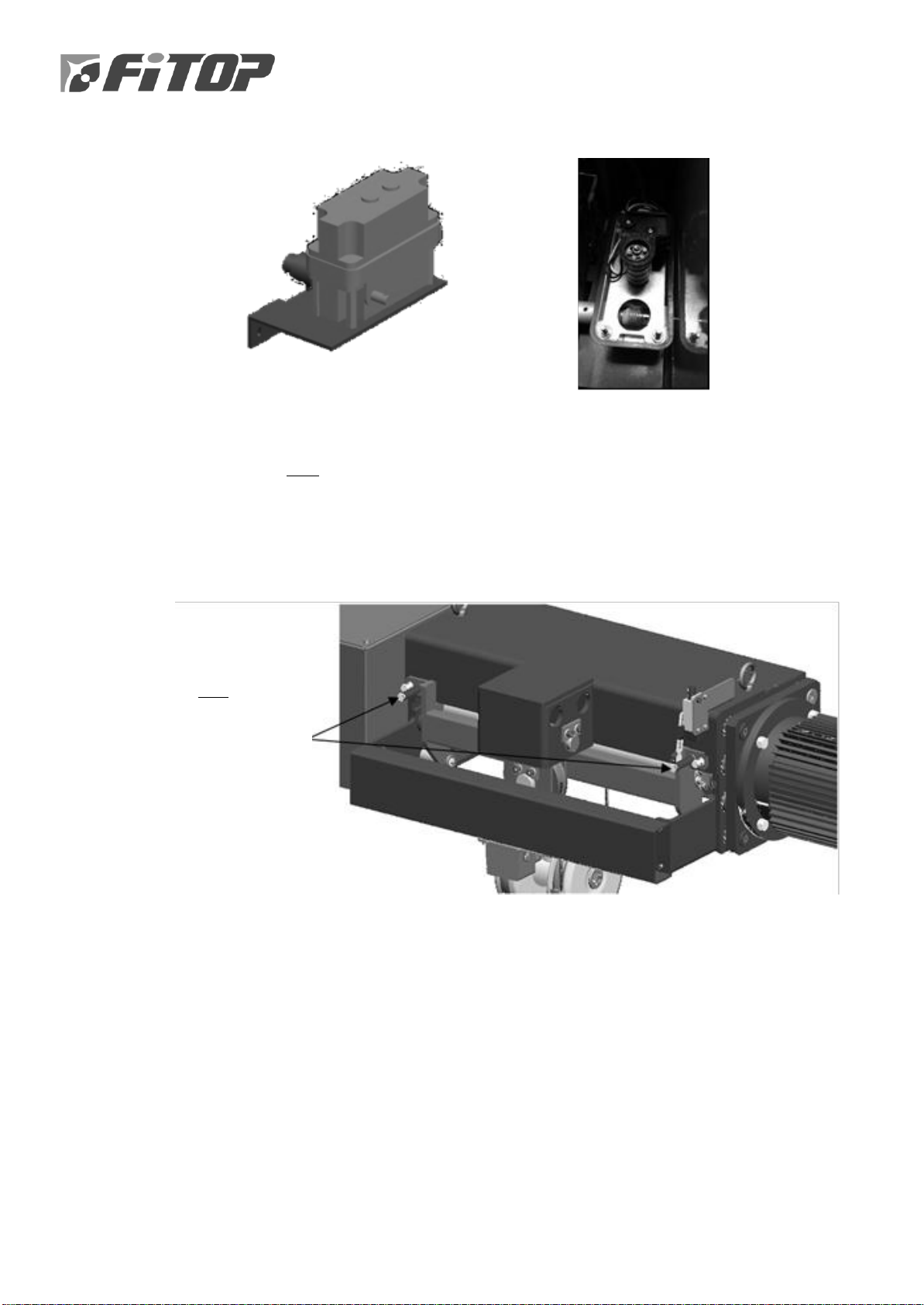
4-5-2. Drum-typed strut rope guide:
Please use the two screws to adjust the rope guide as to touch the wire rope on the
drum; adjust the rope guide limit-switch to ensure that the rope is winded into the
groove, if the rope is out of the groove; press the button (down) so that the rope
could return to its normal way for operation
4-5-3. Overload protection device could prevent over-loading:
In the case of excessive over-loading, the protection device will disconnect the
power of motor to prevent material lifting and declining
Use the two screws
to adjust the rope
guide to touch the
wire rope on the
drum
6
V.IMPROPER OPERATIONS
5-1. Correct Operation
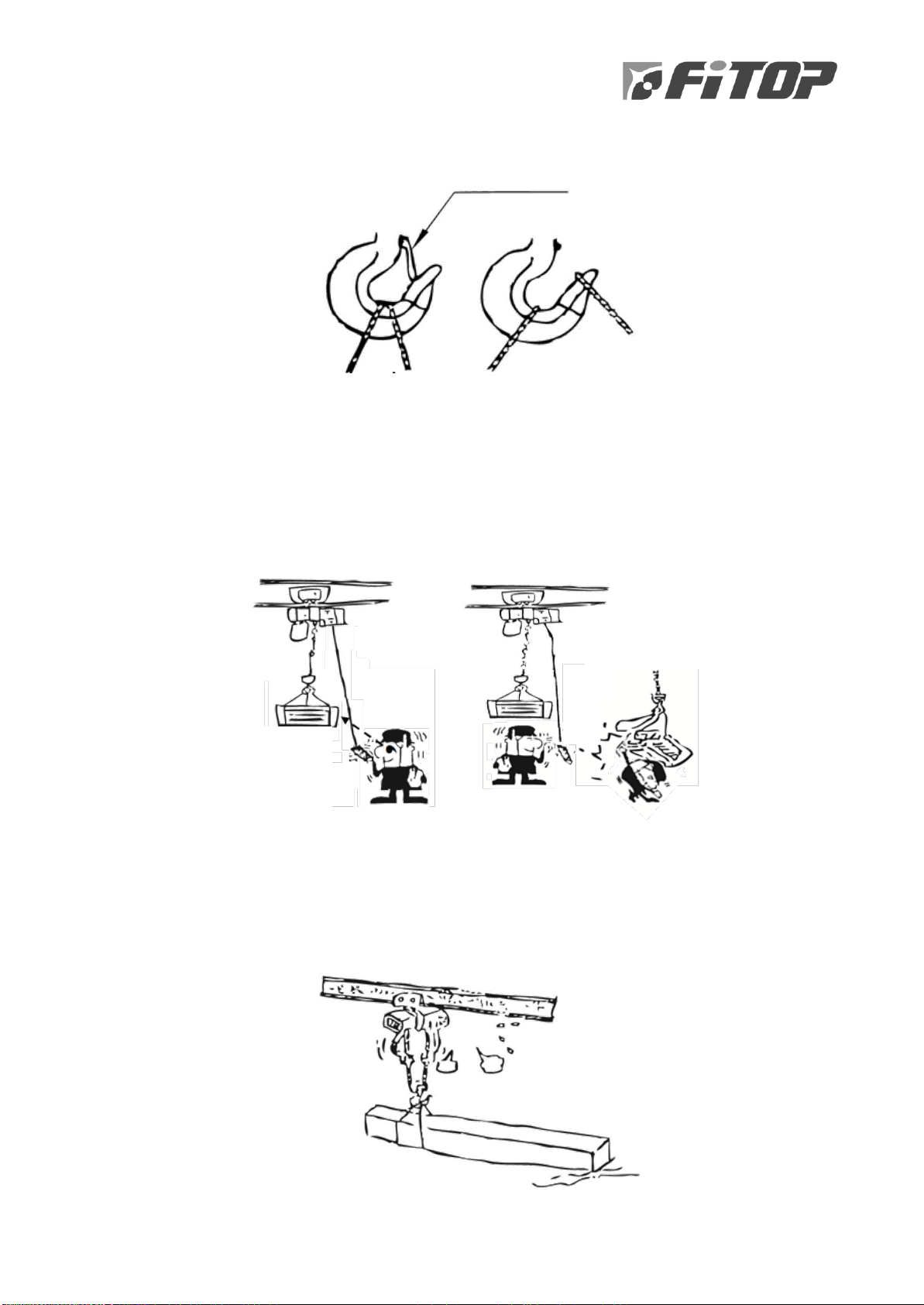
5-1-1. During operation, please be sure that the wire rope is fastened at correct position
for safety; otherwise, with loosened hook, the cargo it hoisted will be fallen and
caused damage
5-1-2. Slightly loosen the tight wire rope; besides, the loose wire rope shall be tightened
steadily
5-1-3. Please make sure the wire rope has been re-organised before operating
5-1-4. Sharp angles could cause wire rope damaged; please use a smooth material to
protect the wire rope at that particular place
5-1-5. Do not impact the cargo before operating as to avoid load falls down
5-1-6. When you lift a single cargo with two hoists, please keep it well-balanced in the
centre of gravity
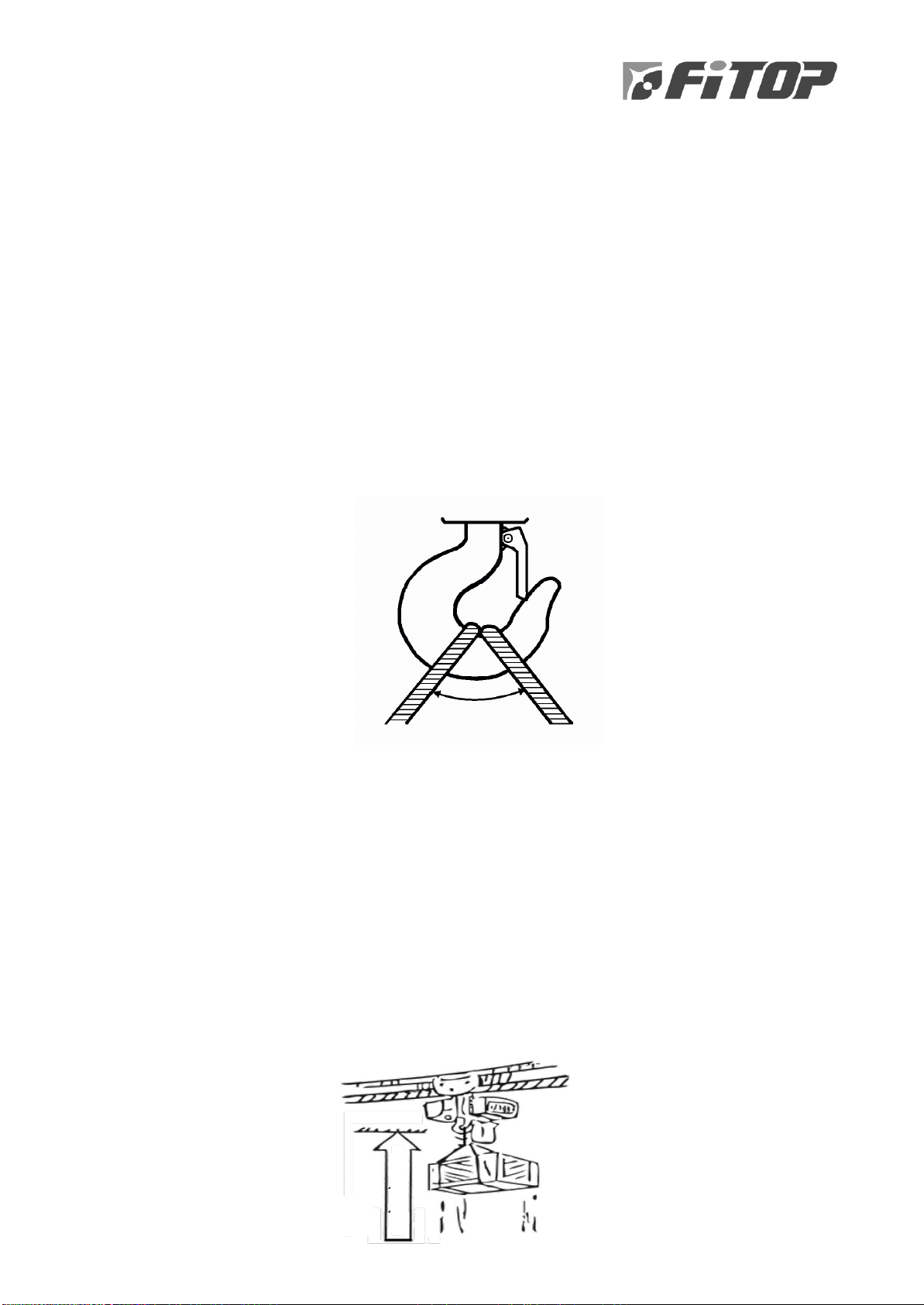
5-1-7. Keep the opening of hook’s wire rope within 60°as shown below:
5-2. Prohibitions
5-2-1. Do NOT lift weights which exceeds its allowable capacity
5-2-2. Do NOT weld a hoisted material and use the hoist to connect ground
5-2-3. Do NOT put the sheave on the ground, because the slings of the drum loosen. If the
drum reverses, will lead the wire rope reversed and fall down. The wire rope will
break down as it escapes from its correct groove
5-2-4. Do NOT load or unload when you could NOT see if there is anything on the ground
or anything between the hook and ground
5-2-5. Do NOT let the hook carries with material and keep it unloaded. It causes danger!
Kindly lift your cargo to its destiny and unload it
5-2-6. When you are lifting a material, the hook must be 2 metres above ground; the hoist
itself shall always be on the top of the material to lift
Max. 60∘
Hook is 2 metres above
ground
2
M
The hoist itself shall be above the
material to lift up

5-2-7. Do NOT let the chain be slant while lifting goods, no matter it is traversing or
travelling. When slant, the angle of traversing should NOT exceeded 15°, and
travelling should NOT exceeded 3°. Moreover, do NOT push the loading onto one
side to avoid slanting
5-2-8. Do NOT move quickly or stop suddenly; must always operate it smoothly. When
lifting, please (1) tight up the wire rope slowly, (2) stop, (3) lift it 20cm above the
ground, (4) stop, ensure its safety, and (5) then lift it
5-2-9. Pay attentions anytime, avoid swinging while lifting your materials vertically
Traversing, do NOT
exceed 15°
Travelling, do
NOT exceed 3°
Tight up the
wire rope
Above the ground
20cm
Roll it up slowly
and stop
Operating
Stop
Avoid swinging
8
5-2-10. Do NOT dis-assemble the Safety Tab of hook for safety
5-2-11. If the lifting have to stop while operating, please let it stop at a zone which is OUT
of a walk-way NOR a working area
5-2-12. Lift the material up to a fixed height, then move it horizontally, the operator must
focus on the load itself; do not let the material pass over any person’s head, and
must operate it steadily to avoid swinging
5-2-13. While operating, must be aware of its conditions, such as extra noise, shaking,
heating, and fumes. If it was happened, must stop using it and check its problem
or inform maintenance engineer
5-2-14. Kindly ensure that the materials are correctly loaded. Please keep your eyes on
the safety since it matters to the happiness of a family
OK
NG!
The operator must
focus on the load
Do NOT let the material
pass over people’s head
Safety tab

5-2-15. Do NOT clean, check, lubricate while lifting materials
5-2-16. You may use the hoist for dis-assembling purposes
5-2-17. Do NOT use the hoist to pull out its lifting rope
5-2-18. If the weight of a material needs to be shared by two hoists, please balance it by,
e.g., 2 sets of 1-ton-capacity hoist, the total load must be less than 1.5 tons
5-2-19. Please press the ON/OFF buttons firmly. Let it stop first, and press button for
going backwards (reverse). If the reverse button is used suddenly, the
consumption will increase, and the motor will become heated. Avoid inching.
Please use hand to press the buttons. Do NOT beat or press two buttons at the
same time
5-2-20. Spiral limit switch up and upper limit switches are the protections for the hoist. If
the load touches the position of up limit, ensure to stop operating; please do NOT
use this function frequently to avoid parts damage and lost this protection. Do
NOT disassemble this spiral limit switch to avoid severe danger
10
VI.MAINTENANCE
6-1. Notes for maintenance
6-1-1. Periodically clean the RAIL of trolley
6-1-2. Periodically check the FUNCTIONS of limit switch
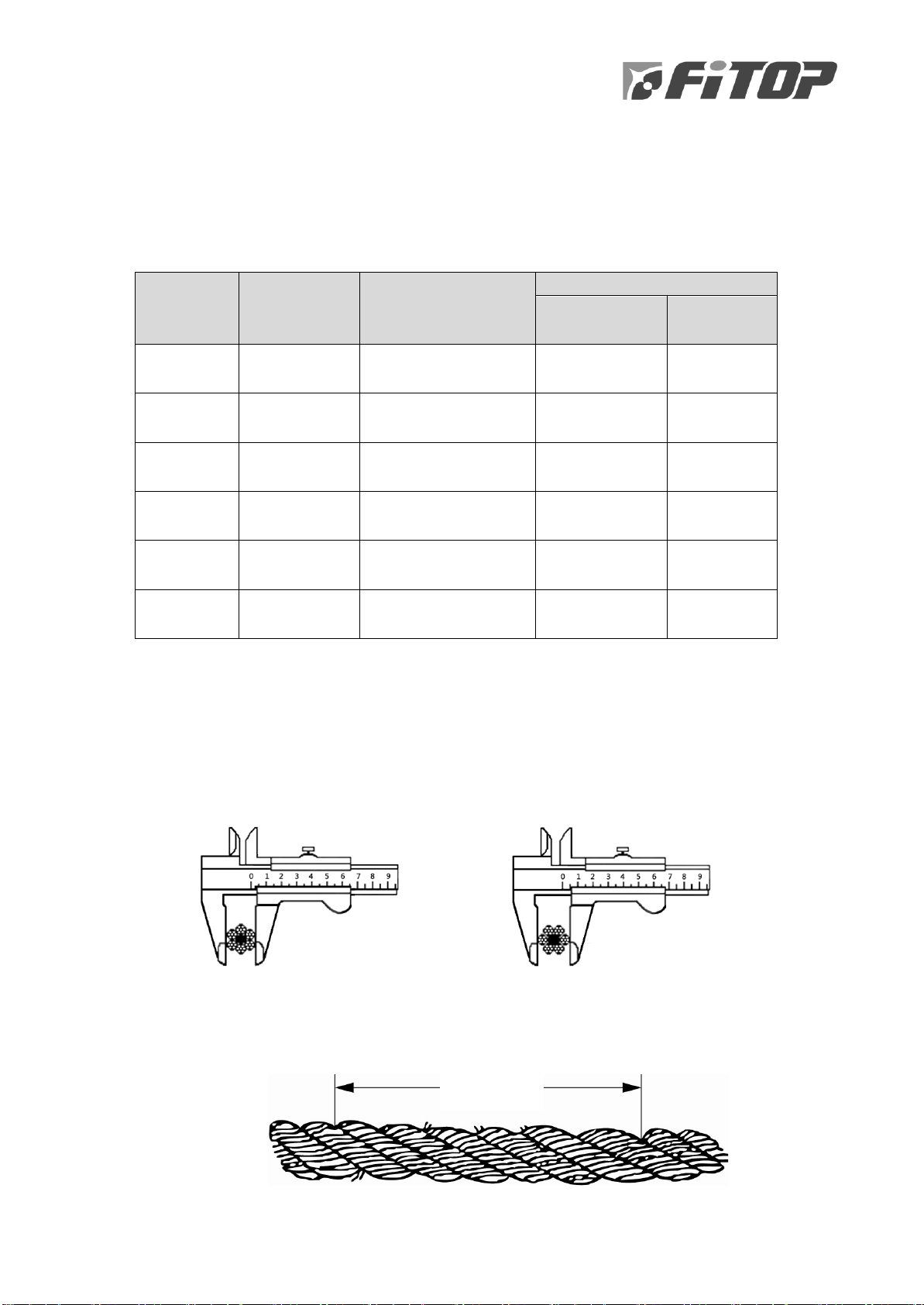
6-1-3. Periodically lubricate the following items as instructed:
Place to
lubricate
Method of
Lubrication
Interval
(Temp.: -10℃~ 60℃)
Lubrication recommended
CPC
(www.cpc.com.tw)
JIS-standard
Gear box
Oil bathing
If necessary
Gear oil #90
Grease No.2
K-2219 (1983)
Gear oil
Wire rope
Smearing
Check it monthly
If necessary
Wire rope oil
W450
K-2220 (1980)
Grease
Bearing
Oil filling
Every year
If necessary
Grease for
Ball bearing
K-2220 (1980)
Grease
Opened
gear
Smearing or
spraying
Check it quarterly
If necessary
Grease No.2
k-2220 (1980)
Grease
Up sheave
& shaft
Oil filling
Check it quarterly
If necessary
Bearing oil No.3
K-2220 (1980)
Grease
Sheave &
shaft
Oil filling
Check it quarterly
If necessary
Bearing oil No.3
K-2220 (1980)
Grease
6-2. Limitations of Use
6-2-1. Wire rope
The wearing of wire rope’s O. D. should NOT exceed 7%; otherwise, a replacement
is necessary
(a) Wrong measuring (b) Correct measuring
The NUMBER of broken threads should NOT exceed 10% of the total thread
number in one (1) unit.
One Unit
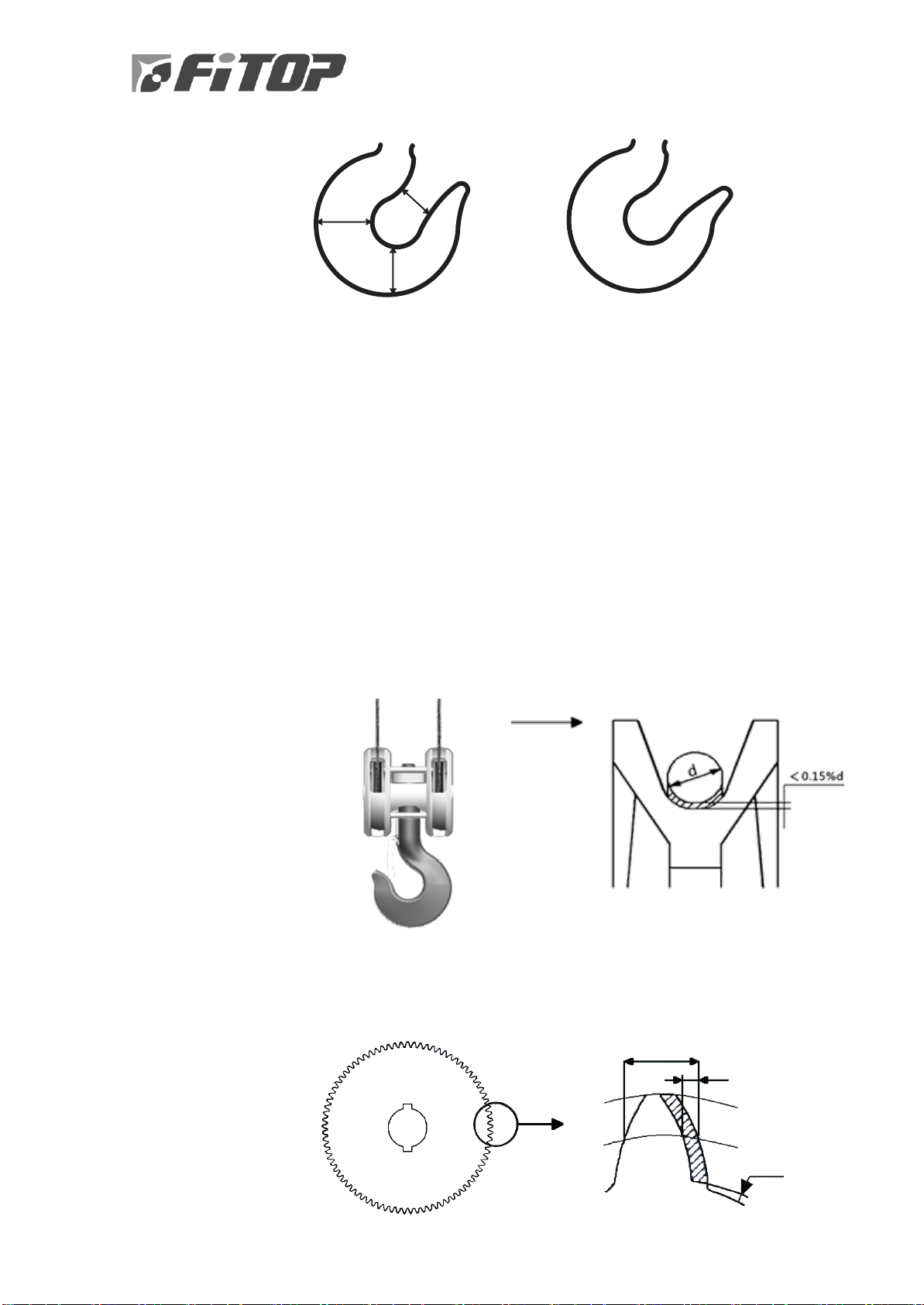
6-2-2. Hook
Chart 1: Chart 2:
NORMAL Hook opening BAD opening
(Do NOT use it)
6-2-2-1. Do NOT use it if the hook is cracked or deformed
6-2-2-2. The Wear and tear’s limitation of H-value is under 5% of standard
thickness
6-2-2-3. If the opening width (B at Chart 1) of hook has been deformed, please
replace it immediately for safety
6-2-3. Sheave
The wear and tear limitation of CAST IRON SHEAVE is under 30% of wire rope’s O.
D.; however, the wear and tear limitation of INNER WALL of sheave would depend
on its condition
6-2-4. Gear
The wear and tear limitation of GEAR depends on the thickness above the pitch
circle.
Thickness
Pitch circle
diameter
H1
H2
B
Wearing
Gap
Blank
diameter
Dedendum
diameter

12
6-2-4-1. The wear and tear limitation of DRIVING GEAR for trolley is at 40%
6-2-4-2. The part of WINDING UP should NOT exceed 30% of original size
6-2-4-3. The first section of GEAR should NOT exceed 10% of original size
6-2-4-4. SHAFT COUPLER should NOT exceed 20% of original size
6-2-5. The wear and tear condition of ELECTRICAL CONNECTION should NOT below
65% of original thickness
6-2-6. The wear and tear of LINING should NOT exceed 50% of original thickness
(Original thickness: 3.5mm)
6-2-7. Wheel
6-2-7-1. The wear and tear limitation of FLANGE thickness is 50% of original
size
6-2-7-2. The wear and tear limitation of WHEEL GROOVE is 5% of original dia.
6-2-7-3. The TOLERANCE of roundness on groove dia. should NOT exceed 1mm
6-2-7-4. The tolerance of Left/Right dia.:
Driving (active) wheel should NOT exceed 0.2%
Driven (passive) wheel should NOT exceed 0.5%

6-3. Items to examine daily
Checking items
Standard of Judgment
Wire rope
▪Prolonged
▪Worn out
▪Deformed
▪Corroded
▪Broken
▪Abnormal prolong condition
▪The thread wiring is exceeded the limitation
▪Deformation is continuing
▪Corrosion is obvious
▪Broken, exceeds its greatest extent
Hook
▪Widened opening
▪Deformed
▪Other damaged defects
▪Performance
▪Safety tab
▪The opening is becoming wider
▪It is curved & deformed
▪Cracked, scared, or other defects
▪Performs smoothly when moving upwards and
downwards
▪If the safe tab is loosened?
Up-limit-
switch
Assembly of up- and
upper-limit
When the loading touches the up- limit-switch,
the power of hoist would be disconnected
Motor
The function of hoist,
trolley and end-carriage
Is the function normal or not? Any noise?
Brake
The function of hoist,
trolley and end-carriage
Check the function of brake, no sliding-down,
and no noise?
Push
Button
Outlook and Operation
▪If the outer shell is damaged or deformed
▪All hoist motion is normal
▪The moving directions of hoist are as the same
as the signs shown on push button
Hanging
tool
Wear and tear
Deformed
Check if it is under abnormal wear and tear
deformed, cracked conditions?
Daily checking point form as Annex 1. (Pg. 26)
6-4. Items to examine monthly
Checking parts 6-7 (pg. 14-15) and 6-8 (pg. 16), the record form Annex 2
(pg. 27-30), checking by the items
6-5. Items to examine quarterly
6-5-1. Check the INSULATION of cable wire and cable
6-5-2. Check all NUTS & BOLTS of connecting part
6-5-3. Check the CABLE of push button pendant
6-5-4. Check all BOLTS on the trolley wheel and motor

14
Examination table as Annex 2. (Pg. 27-30)
6-6. Items to examine yearly
6-6-1. Check and fill in LUBRICANT OIL for every part of the hoist after it has been
operated for one year
6-6-2. Check GEAR BOX of hoist:
Check the wear condition of gear, the function of ball bearing, and the tightness
of locking bolt
6-6-3. Check BRAKE
Check the wear of lining, brake plate, lining’s motion, and test its function
6-6-4. Examine if ELECTRO-MAGNETIC BRAKE is in good condition
6-6-5. Examine MOTOR
Examine if you could hear NOISE when motor runs, please see if the BALL
BEARING is in good condition
6-6-6. Inspect LIMIT SWITCH
Check the wear of contact point, tightness of bolt, and test the switch’s
performance
6-6-7. SHEAVE and WIRE ROPE shall be examined monthly
6-6-8. Check Trolley wheels & end carriage wheels:
Inspect the wearing condition of wheel surface, ball bearing, and gear
6-6-9. If each part has been identified as NORMAL, then lift the goods 10-20cm higher
and decline the goods 10-20cm lower repeatedly. If nothing wrong, general lifting
activity may be started again
Examination form as Annex 2. (Pg. 27-30)

6-7. Structure & Mechanicals
Checking items
Checking items
Beam, saddle, and traveling machinery sections
Beam and saddle
Button switch
1. Check the fixed screw is loosened or not
2. Check the trolley rail is damaged or not
3. Remain rampant in a stopped status
4. Add oil to the gear and shaft
5. Are (i) traveling gear wheel flange and
(ii) flange surfaces wear and tear?
16. Whether it looks weird or cracked
17. Each chain of operation button is complete?
18. Wiring and bolts for earth wire are loosened?
19. Each contact point is good?
20. Control wires are fractured?
Rail
Electro-magnetic brake
6. The scuff on the RAIL is more than 10%
comparing to its original thickness?
7. Are track-bolts loosened?
8. Cracks can be seen on the welded section of
the orbital welding?
9. Wagon or large block buffer is damaged?
21. Whether the actions of brake are correct?
22. Any strange noise, vibration, oblique, or
irregular movements?
23. Whether the gap of brake is normal?
24. Brake disc worn more than 50% of the original
thickness?
25. Braking force is good?
26. Any parts of brake is lost, loosened, deformed,
or wear?
Traveling mechanical device
Wire rope
10. The device is deformed, dropped off, or
bolts loosened?
11. Traveling motor reducer’s bolts are
loosened?
12. From the oil-adding condition of the driven
shaft bearings, the bearing has no weird
noise
13. Wear loosened driven shaft?
14. Cracks on the wheel surface?
15. Rim thickness has exceeded 50% than its
original thickness
27. With or without significant deformation or
corrosion?
28. The balance wheel which in contact with the
side part is normal?
29. The cable is coated with oil?
30. Has it burnt more than 10% of the prime line,
and it has slightly broken? 7% of the wire rope
in nominal diameter is diminished?
31. The condition of the end of the handle and reel
is appropriate
Drum
Oil
32. Cracks on the drum or grooves are obvious?
33. The wire rope is well-tightened on the
drum?
34. The body of drum is deformed?
35. The fixed block on the drum is loosened?
47. The refuelling state of the external gear and
gearbox
48. The gear is obviously cracked or scuffed?
49. Any weird noise during operation?
Wiring inside the machine
50. Has the control box been well-fixed?
51. The appearance of cable is obvious?
52. The screw of each contact is in good condition?
53. Insulation condition is good?

16
Checking items
Checking items
Hook
Security check
36. By visual, any distortion or crackings can be
seen?
37. Opening gauge of the original size has 5%
difference, comparing to its original condition?
38. The contact part of the hook is scuffed more
than 5%, comparing to its original condition?
39. The screw of shaft and nut scuffed?
40. Is the tab or any slip-prevention device not
performing when it should have?
41. Is the condition of hanging fine?
42. Is the condition of the rotation fine?
54. Safety ladders are secure?
55. Hand-rails are secure?
56. Check the function of overload-prevention
device is normal
57. The function of falling-prevention device
(outdoor-typed) is normal
58. Safety sidewalk is clean and has no
corrosions
59. The function of over-winch (upper- and
lower-limit) is normal
60. Traveling and traversing limit switch are
normal
61. The buffer of traveling and traversing
direction is normal
62. The alarm for the straight direction and
warning device are normal
Sheave
Others
43. Sheave (including the balance wheel) wheel
flange and other parts of the ditch, with or
without obvious cracks and wear?
44. Whether the shaft and bearing are obviously
damaged?
45. Key plate, locking pins, stopper bolt, cotter pins
dropped off, loosened, or damaged?
63. Is the licence overdue?
Gear box
46. Cracking or leaking?

6-8. The electricals (including control panel)
Component
Checking items
Component
Checking items
Electric
motor
1. The motor wire is
damaged? Is insulation
fine?
2. Terminal wires are
loosened?
3. Any weird noise when
hoist is running?
4. Three-phase current
balance in full loading?
Power-
feeding
system
Safe rail
21. The scuff of safe rail
22. End-tension device for safe rail
23. Anti-conduction device
24. Insulant is abnormal and its
condition of insulation
Control
panel
5. Fixed screw of panel
6. Fixed contactor &
transformer
Current Collector
25. The scuff of collector
26. Oil feeding to the mechanism
27. The insulating state of the
system
28. Fix terminal, bolt, and screw
Electro-
magnetic
contactor
7. The absorbent surface,
enamelled wire, and weird
noise of steel core
8. Contact surface of the
slice
9. The scuff of contact point
10. The moving status of
contactor
Power-supply cable
29. Scuffs of the cables that are
exposed
30. Extension of cable
31. Terminal, bolt are well-
screwed
32. The leading mechanism of
cable
Interior
wiring
11. Fix the terminal of
Contactor
12. Internal wiring and
insulation
13. Mounting bolts
14. Conduction device
Other
devices
Signal light
33. Fixing part of terminal
Push
button
(pendant)
15. The slice of contact
surface
16. Keep the contact depth of
contact point
17. Keep the direction of
movement
18. Cable inlet
19. The condition of box and
cover
20. The protection of the wire
rope
Lightening device
34. Fix the terminal
35. Mounting part & break-proof
bulb
Limit switch
36. Contact point of contactor
37. The spring of contactor point
38. Limit lever deformed?
39. Performance & its position of
action
40. Bolt mounting

18
VII. TROUBLE-SHOOTING AND MAINTENANCE
7-1. Notes of Maintenance
7-1-1. Before the maintenance work of runway beam and hoist, you MUST (1) advise with
public notice within the factory, and (2) disconnect the power supply and remove
lead wire. The work could only be started in un-loading statues.
7-1-2. Do NOT maintain or repair machine when the power supply is on.
7-1-3. After the maintenance is completed, close all doors or covers of the hoist. Do NOT
leave any tools or spares on the hoist or the rail.
7-1-4. When implementing Chapter 7-2 (Mechanicals), please CONTACT the supplier or
the regional distributor in advance.
7-2. Mechanicals
Trouble
Possible causes
Trouble-shooting
1. Wire rope is NOT on the
groove of drum when rolling
(1) The hoist swinged, wire rope
jumped over, caused overlapping
(2) Wire rope scuffed or deformed
(1) Roll wire rope DOWN and re-roll
wire rope UP
(2) Contact the supplier or the
regional distributor
2. Loud noise
The speed reducer is over-scuffed
Contact the supplier or the regional
distributor
3. The loosen motion of disk
brake is becoming slower
(1) Too large the gap between the
lining and brake plate
(2) The inner hole of sliding portion
is rusted or burnt (by visual
inspection)
Contact the supplier or the regional
distributor
4. Disc brake takes long time
to perform functions
(1) The inner hole of sliding portion
is rusted or burnt (by visual
inspection)
(2) Can see there are dirt on the
sliding surface of brake plate
(3) The manually-loosened bolt is
performing
(4) The brake spring is loosened
Contact the supplier or the regional
distributor
5. Main hoisting sliding down
(1) Too large the brake gap
(2) Brake Lining is scuffed
(3) The brake spring is loosened
Contact the supplier or the regional
distributor
6. Trolley sliding
(1) The brake adjustment screw is
not tightened
(2) The lining is scuffed
(3) The brake spring is loosened
Contact the supplier or the regional
distributor
7. End carriage sliding and
running unevenly
(1) The brake-adjustment-screw is
not tightened
(2) The lining is scuffed
(3) The brake spring loosened
Contact the supplier or the regional
distributor
Table of contents
Popular Chain Hoist manuals by other brands


RED ROOSTER
RED ROOSTER TCS-500-LF user manual

Tractel
Tractel DD Series manual

POWERTEX
POWERTEX PCB-S1 Instructions for use

J. D. NEUHAUS
J. D. NEUHAUS PROFI 25TI Original operation and assembly instructions

Ingersoll-Rand
Ingersoll-Rand KX Series Product Maintenance Information

XTline
XTline XT108600 Operation manual