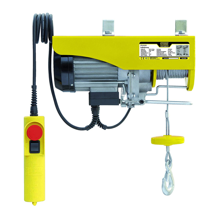
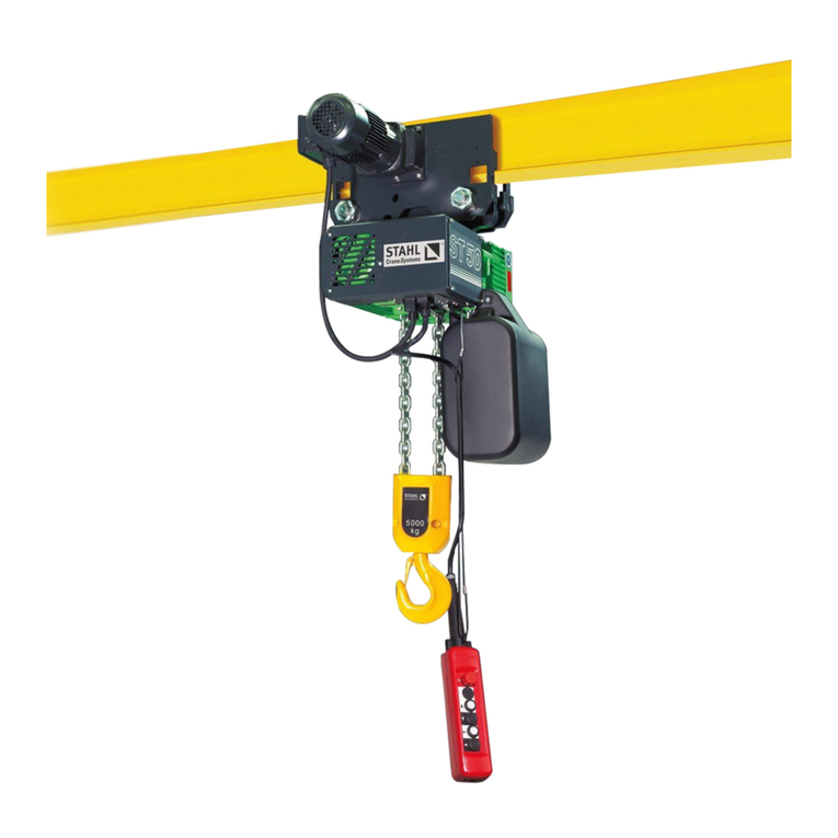
Starke STK User manual

1 | P a g e
STK Electric Chain
Hoist
Models
STK0526 (½ ton)
STK1026 (1 ton)
STK2026 (2 ton)
STK3021 (3 ton)
STK5011 (5 ton)

2 | P a g e
Table of Contents
Section
Preface ------------------------------------------------------------- 3
Safety Precautions & Warnings ------------------------------- 4
Basic Specifications --------------------------------------------- 5
Service Life --------------------------------------------------------- 6
Lifting Motor Usage ---------------------------------------------- 8
Pendant Options -------------------------------------------------- 9
Electrical & Chain Data --------------------------------------- 10
Mechanical Drawings & Data -------------------------------- 10
Hoist Drawings ---------------------------------------------------- 11
Safety Information ----------------------------------------------- 16
Assembly and Installation ------------------------------------- 17
Operation and Maintenance ---------------------------------- 18
Electrical Schematics ------------------------------------------- 22
Parts Lists ---------------------------------------------------------- 23
Trouble Shooting Guide ---------------------------------------- 36
Warranty Information -------------------------------------------- 38
SN________________________
STK Hoist Single Speed Owner’s Manual V1.2 5.2023

3 | P a g e
1. Preface
Thank you for purchasing a Starke STK Hoist.
It is our intention that this document will help address any concerns you may have about the
installation, operation, and maintenance of your hoist. The standard hoist comes as a 460VAC / 3
phase unit, other configurations are optional. Please verify that the power supply you intend to hook
up to this hoist matches the specified power requirements of this hoist system.
Upon receiving your hoist / crane system and its components please securely store all these
components in a clean and dry space. Please ensure that all end truck, trolley, and hoist system
assemblies and associated electrical panels are all protected from moisture during shipping and
storage prior to and during installation. Following these instructions will help ensure a successful
installation of the system and maximize your productivity.
Thank You,
Starke America.
STARKEAMERICA.COM

4 | P a g e
!!! IMPORTANT INFORMATION !!!
Please read, understand, and follow all aspects of this manual before the assembly and
installation of this hoist system. Please observe and follow all safety and warning information
during the operation of this system. Failure to do so may result in serious property damage,
personal injury and/or loss of life.
Safety Precautions:
Because of the heavy loads being transported by this system, the operator and those around the
serviceable area must be attentive to and aware of all potential risks involved with the operation of
this system. The operator must pay careful attention to and abide by the safety rules and warnings
listed below and found throughout this manual. All Safety Rules and Warnings must be followed.
Warnings:
1. Before operation, the operator must have a clear and unobstructed view of the entire service
area of this system.
2. For your safety DO NOT attach the electrical supply wires to this unit before the completion
of installation!
3. Before operation, inspect the hoist system to be sure it is in proper working condition. Check
for any possible obstacles and/or personnel in the service area of the hoist system.
4. While operating the hoist system, the operator must take caution to prevent a situation where
the changing of direction of travel and the resulting abrupt force may cause the load to swing.
This may cause an overload of the trolley and/or hoist and loss of the load.
5. DO NOT modify this unit in ANY way or operate the unit in an OVERLOADED OR
DAMAGED CONDITION. Any attempt to do so will put you, others, and property at serious
risk.
6. Repairs to this unit must be performed by qualified repair facility. Contact Starke America to
locate the nearest repair facility. See warranty information at the end of this manual.

5 | P a g e
2. Specifications
2.1 Table of specifications
The specifications in the following table are applicable to all electric chain hoists.
Table 2.1
Design Relative Humidity % <= 85% RH
Design Temperature Rating 60F to 104F (normal operating range)
Protection Class Hoist IP 54
Pendant IP 54
Hoist Noise 81 (dB)
Note:
(1) If the working environmental conditions are outside of the recommended values in
the table, please consult your dealer for further guidance.
(2) The standard noise measurement is read at 1 meter from the hoist under normal
operation.

6 | P a g e
2.2 Service Life
The service life expectancy and safe operation of the electric chain hoist can be realized only if it is
operated in accordance to the following. The European Materials Handling Federation, known as
‘FEM’ are a standard body for the material handling industry and are publishers of the FEM Hoist
Duty Classifications.
The design of this hoist conforms to the rating 1Am of FEM (Table 2.21)
DETERMINING THE FEM HOIST DUTY SERVICE CLASSIFICATION
When the load spectrum and the average daily
operating time of the hoist are identified, the duty
service classification of the hoist is obtained from
this table.
The average operation hours per day and total
operation hours are calculated based on load
distribution.
LOAD SPECTRUM
The load spectrum is the magnitude of the load over the duration of the hoist’s operation and the
calculated daily operating time. The basis for calculations is in accordance with FEM standards that a
hoist has a 10-year serviceable lifetime.
LIGHT USE
Light use would be defined as occasional full loads, usually light loads and small fixed loads (typically
a light duty workshop crane with single shift operation).

7 | P a g e
MEDIUM USE
Medium use would be defined as occasional full loads, usually light loads and average fixed loads
(usually a medium duty workshop crane with single shift operation).
HEAVY USE Heavy use would be defined as repetitive full loads, usually average loads, and heavy
fixed loads (expected to be a heavy-duty crane with one or to shift options).
VERY HEAVY USE
Very Heavy use would be defined as usually almost full loads and very heavy fixed loads (this would
be two to three shift operations with magnets below the hooks).

8 | P a g e
Table 2.2.22 Lifting motor usage data
2.3 Safety features
1. Magnetic slide brake is a unique design by which it releases when the motor stator is energized,
and the magnetic field pulls the brake hub from the friction cup. When power is removed it
immediately engages and halts the motors rotation.
2. The hook is forged of high tensile strength steel and heat treated to ensure maximum rigidity and
hardness. It is equipped with a spring-loaded safety latch for securing lifting rigging devices in place.
The lower hook assembly is supported within a ball bearing structure to allow easy rotation of the
load.
3. The control system includes high quality electrical contactors and is protected with a standard
phase monitoring system to ensure proper operation. This is to ensure that the motor is protected in
the case of a power loss of any leg(s) and proper rotational direction of the lifting motor.
4. Upper and lower lifting limit switch is standard equipment on our Starke hoists to prevent damage
to the chain and pulley system in the event of an operator error.
5. Control pendant options are all equipped with an emergency stop (Estop) button that is a manual
reset type. This is to immediately stop all functions of the hoist system in the event of an emergency,
it can also be used to secure the hoist system from unintentional activation.
Group
Intermitted operation
Continuous Operation
F.E.M
ISO
Cycles/h
Starts/h
ED(%)
Operation cycle/min
1 DM
M1
15
90
15
7.5
1 CM
M2
20
120
20
7.5
1 BM
M3
25
250
25
15
1
AM
M4
30
180
30
15
2M
MS
40
240
40
30
3M
M6
50
300
50
30
4M
M7
60
360
60
60
SM
MS
60
360
60
>60

9 | P a g e
2.3.1 Pendant options
Pendant modes of motion are to be specified to dealer upon ordering hoist.
a. In a fixed position installation of the hoist a 1-motion pendant would be required.
b. If a hoist and motorized trolley is specified then a 2-motion pendant would be required.
c. If a hoist, motorized trolley, and motorized bridge are specified then a 3-motion pendant is
required.
d. Another option is a wireless pendant control system that again can be customized to your
application by your Starke America dealer.
1 Motion Pendant 2 Motion Pendant

10 | P a g e
2.4 Electrical and Chain Information
2.5 Mechanical drawings & Data
Chain Falls Capacity(ton) H A B D E I J K L M N Chain Size mm
1 0.5 455 566 266 285 165 ᶲ35 27 ᶲ34 25 17 17 6.3
1 1 520 627 302 300 176 ᶲ42 32 ᶲ41 32 24 24 7.1
1 2 640 733 343 430 265 ᶲ48 38 ᶲ49 40 28 28 10
1 3 685 733 343 430 265 ᶲ59 48 ᶲ59 48 34 34 11.2
2 5 870 733 343 430 325 ᶲ59 48 ᶲ60 48 42 42 11.2
Capacity (Ton)
0.5
1
2
3
5
Chain Fall
1
1
1
1
2
Lifting Height
Std.
20’
Chain
Dimension (mm)
6.3
7.1
10.0
11.2
11.2
Lifting Speed
(FPM)
26
26
26
21
11
Supply Voltage
230/60/3
460/60/3
E.D. Rating (%)
40
40
40
40
40

11 | P a g e
Hook Mounted Hoist

12 | P a g e

13 | P a g e

14 | P a g e

15 | P a g e

16 | P a g e
3.0 Safety
Safety Tips for Overhead Crane Operation
1) Before use, ensure the crane is suitable for the planned hoisting task. Confirm it has appropriate
travel, lift, and capacity.
2) Visually and physically inspect the crane before use. Check for damage, wear, and proper
operation of all functions.
3) Confirm the load weight. Check the capacity of all equipment including the hardware, rope, and
slings. Do not exceed these capacities.
4) Select the right sling for each lift. Inspect slings and other rigging hardware before use for wear,
stretch, or other damage. Do not use damaged or defective slings. Use softeners around
sharp corners. Do not splice broken slings.
5) When communicating with a crane operator, use clear agreed-upon signals. Except for the stop
signal, the crane operator should follow instructions from only one person –a designated signaler.
Where a wired or remote controller is used, the operator should become familiar with all of its
functions before lifting the load.
6) Warn all people in the load lift area before starting the lift. Ensure that the path of the load is clear
of persons and obstructions. Do not lift loads over anyone. Center the crane hoist over the load
before hoisting to prevent swinging of the load.
7) Slide the sling fully onto the hoisting hook and ensure the safety latch is closed. Do not load the
hook tip or hammer a sling into place.
8) Secure unused sling legs. Do not drag slings or leave loose materials on a load being hoisted.
9) Keep hands and fingers from being trapped when slack is taken out of a sling. Step away before
the lift is started.
10) Move the load and controls smoothly. Minimize load swing.
11) Walk ahead of the load during travel and warn people to keep clear. Use a tagline to prevent
rotation or other uncontrolled motion. Raise the load only as high as necessary to clear objects. Do
not ride on the hook or load.
12) Set loads down on blocking, never directly on a sling. Do not pull or push loads out from under
the hoist.
13) Do not leave the load (or the crane) unattended while the load is suspended.
14) Where crane operation by other personnel must be restricted, employ lockout and tagging
procedures.
15) Store slings off the floor in a clean, dry location on hooks or racks. Do not leave slings,
accessories, or blocking lying on the floor.

17 | P a g e
4 Installation
4.1 Unpacking
Upon opening the crate that the hoist is shipped in, please inspect the hoist for any signs of damage
to the power cable, gearbox, and motor shell that may have occurred during shipping. You should find
in the crate, the hoist, chain bag, control pendant (with 3 meter cable), bottle of chain oil, and the
owners documentation. It is a good idea to write down the hoist model and serial number and the
date it was received in the manual in the space provided.
4.2 Power requirements
Please verify the power supply voltage you intend to use matches the hoist, by default the hoist will
be configured for 460Vac 3 phase power. The hoist can be ordered wired for 230Vac 3 phase
operation or can be field modified prior to installation if required (see schematic for wiring chart).
Note: The power supply voltage should be +/- 10% of the operating voltage the hoist is configured for.
If the hoist is operated outside of this specification damage to the lifting motor is possible.
4.3 Installation
Warning: Do not connect the power supply prior to completing the physical installation of the
hoist system. Potential damage and/or injury may occur.
4.3.1 Upper hook assembly
Before installing the hoist, please confirm the entire upper hook assembly has been completely
assembled and mounted to the hoist body securely. Check the chain connecting pin is securely in
place. Hang the hoist to the support structure carefully and check all fasteners are secured.
Note: If the hoist system is equipped with a Starke motorized trolley the hook will be omitted and the
suspension lug will be required to attach the hoist to the trolley.
4.3.2 Chain bag
Install chain bag to the bottom of hoist body with the supplied hardware, note that the brackets on the
chain bag are offset slightly to allow the bag to hang level.

18 | P a g e
4.3.3 Electrical connection
As a precaution, please confirm the power supply matches the power requirements of the hoist
system. Connect the power supply and verify proper phasing to the hoist system, this hoist has a
phase monitoring system and may not allow hoist to operate properly if phasing is incorrect.
It is recommended that a qualified installer perform the set up and testing of this system.
4.3.4 Operational testing
a. Test the emergency stop button on the control pendant. With the E-stop button depressed the hoist should not operate
when any pendant button is activated. If any button activates hoist while E-stop is depressed, do not use the hoist and
contact your dealer for further information. If all is well then grab the E-stop button and rotate clockwise, the button should
pop up and make a slight clicking sound, at this time proceed to the next test.
b. Verify chain is not twisted or askew by examining the individual chain link weld points. For proper operation the weld
points must be in a parallel orientation as shown below (left). If the chain is reeved and twisted observe the illustration
below (right) to remove twist in chain.
c. Press the down button on the pendant and hold until the limit spring on the chain touches the limit switch plate, when
the limit trips the hoist lifting motor should stop.
d. Next press the up button on the pendant and hold until the chain is retracted fully upward, and the limit switch is tripped
and lifting motor stops.
e. Lubrication of the chain will play an important part in the service lifetime of the hoist system. On initial installation apply
the bottle of oil (included) to the chain and evenly disperse with cloth. The best method is to extend the chain to the lowest
point then start applying lubricant at the base of the hoist and working your way down the chain to hook. After application
run the chain fully up and fully down several times to insure even dispersion of oil on all moving parts.

19 | P a g e
5. Operation
After all the appropriate assembly and checkout has been completed it is now time to have the
hoist system “Pre-Use inspected” by a qualified crane service provider and document any
deficiencies that may be discovered and correct them. Once all commissioning and testing are
complete the hoist system can be placed into service and begin to help you increase your
productivity.
It is recommended to have an operator certification process that includes training by a qualified
agency and following the safety tips in section 3 (Page 20) of this manual. Properly certified
operators may help reduce potential risks in day-to-day use of the system and protect your
employees from injury and property damage. Knowing proper operation of the hoist system will
also maximize the service life of the system to your business and return on the investment you
made in this Starke hoist.
6. Maintenance
6.1 General maintenance
6.1.1 Daily pre-use inspection (no load)
a. Verify power is available and test the operation of the Estop function.
b. Test upper and lower limit switch functionality on hoist and any other motions the
system is capable of.
c. As motor is operating listen for any unusual sounds such as grinding or excessive
humming, hammering, stuttering. If so, place the hoist out of service until properly
inspected by qualified personnel.
d. Check chain condition and look for any signs of excessive wear or foreign debris and
that adequate lubrication is present. Correct as necessary.
e. Inspect hook assembly for signs of damage or wear and that hook safety latch is in
good condition.
Note: Keep a daily log or checklist of these results and run times of the system per day.
Good record keeping will help when planning for routine maintenance of the system and
maximizing service life.

20 | P a g e
6.1.2 Monthly Inspection
Included with the hoist is a chain test gauge that is attached to the pendant cable. This offers a
convenient way to perform the following checks. See figures below for reference.
Intermodal distance Diameter gauge
a. Perform a thorough inspection of the chain. Look for excessive wear on chain links as
well as distortion or stretching of the links. Measure internal and external length
dimensions of the links. See table 6.1 for nominal dimensions and if the measured
values exceed 5% of specifications the chain must be replaced.
b. Inspect the chain link diameter and if the measured value is 10% less than the
specified diameter the chain must be replaced.
Diameter Capacity Internal Length Internal Width External Width
mm ton mm mm mm
6.3 0.5 19 7.5 20.5
7.1 1 21 8.9 23
10 2 30 12.5 33
11.2 3 & 5 34 14 37.2
Table 6.1
This manual suits for next models
5
Table of contents
Other Starke Chain Hoist manuals
Popular Chain Hoist manuals by other brands

Hitachi
Hitachi L Series Service manual

HADEF
HADEF 29/06AP-EX Installation, operating and maintenance instructions

Ingersoll-Rand
Ingersoll-Rand CL125K Installation and Operation Information

POWERWINCH
POWERWINCH H500 operating instructions

Tractel
Tractel Tirak Blocstop BSO XE 301 P operating manual

KITO
KITO EQ series owner's manual