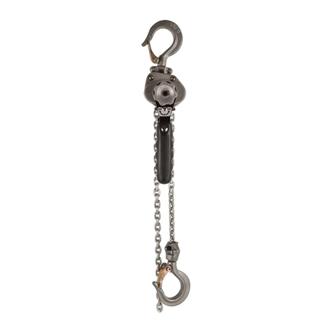
Jet VLP Series User manual

M18-MH110302-308
Operator’s MANUAL
VLP SERIES LEVER CHAIN HOISTS
Prod. No. 110302
110303
110304
110306
110307
110308
Mod. No. VLP-75-5
VLP-75-10
VLP-150-5
VLP-150-10
VLP-300-5
VLP-300-10

2
TABLE OF CONTENTS
Warranty policy.............................................................. 2
Information for your safety............................................ 3
Prior to installation......................................................... 3
Safety precautions ........................................................ 3
Operation....................................................................... 4
Inspection and maintenance ........................................ 5
Hooks............................................................................. 6
Chain.............................................................................. 7
Disassembling and assembling ................................... 7
Parts breakdown ........................................................... 8
Parts list ......................................................................... 9
WARRANTY POLICY
JET EQUIPMENT AND TOOLS LTD.
(JET®) makes every effort to ensure
its products are manufactured to the
highest standards and are guaranteed
against defects in materials and
workmanship when the product is
used for the purpose for which it was
designed.
This guarantee applies only to JET
products purchased new from a JET
authorized distributor.
JET product warranties are extended
to the original retail purchaser only.
This warranty does not apply to any
product showing signs of abuse,
misuse, alteration, or having been
improperly maintained or repaired.
This warranty does not cover
damage attributable to normal wear
and tear.
Any JET product that fails during
normal use and is within the
specified warranty period for that
product will be repaired or replaced
at JET’s discretion. Repairs and/
or replacements are warranted as
described for the specific product and
only for the remainder of the original
warranty period.
Repair or replacement is the
exclusive remedy for defective product
under this warranty.
Warranty is expressly in lieu of
all other warranties, including the
implied warranty of merchantability or
any implied warranty of fitness for a
particular application.
Any JET product for which there is
a warranty claim should be returned
PREPAID to an authorized JET
distributor or service centre. Authorized
Warranty Depots are found at
surewerx.com
ALL warranty claims must be
accompanied by proof of purchase and
an explanation of the defect or failure.
It is the customer’s responsibility to
provide this information.
JET shall not be held liable for any
consequential or incidental damages
for breach of any expressed or implied
warranty on their products. No claims
for damages of any type will be
considered and all products are sold
with this understanding.
Any costs incurred to obtain warranty
consideration or services are the
Customer’s responsibility including
shipping and handling, travel, lost time,
or lost production.
SPECIFIED WARRANTY –
MATERIAL HANDLING
1 Year Limited Warranty
Chain Hoists Hand Cable Pullers
Air Hoists Lever Chain Pullers
Electric Hoists Grip Pullers
Electric Trolleys Manual Adjustable
Trolleys
Drum Clamps Beam Clamps
Plate Clamps Blocks and Sheaves
Pallet Trucks Mobile Lift Tables
Winches
GENERAL INFORMATION ON JET CHAIN HOISTS AND PULLERS
Customs Lifts – Custom lift lengths are
available, however, custom lift hoists
and pullers are NOT returnable.
CAUTION: be sure that supporting
structures and load-attaching devices
used in conjunction with hoists,
provide an adequate safety factor to
handle the rated load plus the weight
of the equipment. If in doubt, consult a
qualified structural engineer.
This equipment is not to be used for
lifting, supporting, or transporting
people, or lifting, supporting, or
transporting loads over people.
IMPORTANT: Before installation
and operation, see maintenance and
operations manual for additional
warnings, precautions and operating
instructions.
NOTE: Batteries supplied with certain
products may have been subjected to
long shelf life, resulting in low energy
or a dead battery. Please source
replacement batteries locally. Please
follow instructions in the manuals for
products using rechargeable batteries.
Dead batteries do not constitute a
warranty claim.

3
INFORMATION FOR YOUR SAFETY
It is the responsibility of the owner/user to install, inspect,
test, maintain, and operate these lever hoists in accordance
with ASME B30.21, Safety Standard for Manually Operated
Lever Hoists.
These general instructions deal with the normal installation,
operation and maintenance situations encountered with the
lever hoists described herein. The instructions should not
be interpreted to anticipate every possible contingency or to
anticipate the final system or configuration that uses these
lever hoists.
These instructions include information for a variety of lever
hoists. Therefore, all instructions and information may not
apply to one specific lever hoist. Disregard those portions of
the instructions that do not apply.
If the lever hoist owner/user requires additional information,
or if any information in these instructions are not clear,
contact your local JET®Material Handling Products
distributor.
This lever hoist should not be installed, operated, or
maintained by any person who has not read all the contents
of these instructions, and ASME B30.21, Safety Standard for
Manually Operated Lever Hoists. Failure to read and comply
with these instructions or any of the warnings or limitations
noted herein can result in serious bodily injury or death, and/
or property damage.
Only trained and qualified personnel shall operate and
maintain this equipment.
Equipment described herein is not designed for, and should
not be used for lifting, supporting, or transporting people.
User should not use this lever hoist in conjunction with other
equipment unless necessary and/or required safety devices
applicable to the system are installed by the user.
Modifications to upgrade, rerate or otherwise alter these lever
hoists shall be authorized only by the original equipment
manufacturer or qualified professional engineer.
SAFETY PRECAUTIONS
A. READ these instructions and ASME B30.21, Safety
Standard for Manually Operated Lever Hoists before
installing, operating, or maintaining this equipment.
B. WARN personnel of approaching loads.
C. DO NOT:
1. Lift more than rated load.
2. Operate lever hoist when it is restricted from forming
a straight line with the direction of loading.
3. Operate with twisted, kinked, or damaged chain.
4. Operate if chain is not seated in sheaves or
sprockets.
5. Wrap chain around load or use chain as a sling.
6. Operate unless load is properly applied to the
saddle or bowl of the hook.
7. Operate if load is applied to the tip of the hook.
8. Operate with damaged or missing hook latches.
9. Lift people or lift loads over people.
10. Operate with side-pulling or side-loading of load to
lever hoist.
11. Operate a damaged or malfunctioning lever hoist.
12. Operate with other than hand power.
13. Remove, deface, or obscure warning label or labels
on lever hoist.
14. Leave load suspended when lever hoist is
unattended unless specific precautions have
been instituted and are in place.
15. Lengthen load chain or repair damaged load chain
by welding.
16. Use chain as a ground for welding.
17. Hammer on lever.
18. Use extensions on lever.
19. Lift one load with more than one lever hoist, unless
each lever hoist is rated to support the entire load
in the event one or more lever hoists is disabled,
shifting load to the other lever hoists.

4
PRIOR TO INSTALLATION
Check for damage during shipment. Place claim with carrier if any damage is discovered. DO NOT install or use a
damaged lever hoist. Check and verify that structure or other equipment that will support the lever hoist has a rated
load capacity equal to or greater than the rated load capacity of the lever hoist to be used.
OPERATION
Before Initial Operation Of Hoist:
1. Read and comply with all instructions and warnings
furnished with or attached to lever hoist.
2. Check lubricant.
3. Check operation of brake.
4. Check that chain is properly seated in sheaves and that
chain is not twisted, kinked, or damaged.
Before Each Shift:
1. Inspect hooks for nicks, gouges, cracks, and signs of
pulling apart or twisting.
2. Inspect hook latch for proper operation.
3. Check chain for kinks or twists.
4. Check operation of brake.
5. Replace warning label if missing or illegible.
Before Operating:
1. Be certain all personnel are clear
of the load to be lifted and moved.
2. Make sure load will clear stock piles, machinery, or other
obstructions when hoisting and travelling the load.
3. Eliminate any twists or kinks in the load chain.
Incorrect
To Raise Load:
1. Set change lever on handle to “UP” position.
2. Operate handle to move load.
To Lower Load:
1. Set change lever on handle to “DOWN” position.
2. Operate handle to move load.
TO ADJUST CHAIN LENGTH:
To Shorten:
Set change lever to “NEUTRAL” and turn feed hand wheel
clockwise or pull free end of chain.
To Lengthen:
Set change lever to ”NEUTRAL” and turn feed hand wheel
counter-clockwise or pull hook end of chain.
Brake Lock:
If the lever hoist is unloaded by means other than operating
the lever, or if the bottom hook is pulled tight against the
hoist body, brake lock can occur. To unlock brake, move
selector to DOWN position and pull sharply on lever.
To Adjust Brake:
1. Remove cotter pin from castle nut on feed knob.
2. Screw castle nut on snugly, then back nut off just
enough to line up holes for cotter pin. Replace
cotter pin.
Shock Loads:
Do not allow a load to drop, such as over the edge of a
platform, while connected to a lever hoist. The sudden
drop, even of an insignificant distance, can cause a severe
momentary overload, seriously damaging the lever hoist and
possibly resulting in the loss of the load. This can occur at
loads well under the rated capacity.
Correct
Correct
OPERATION
REPLACEMENT OF CHAIN:
USE ONLY GENUINE JET GRADE 80 REPLACEMENT LOAD CHAIN

5
INSPECTION AND MAINTENANCE
Prior to initial use, all new, modified, and repaired hoists shall be inspected in accordance with Table 2.
Thereafter, inspections shall be conducted at intervals shown in Table 1; and items to be inspected are indicated
in Table 2 by F (Frequent) or P(Periodic).
Frequent Inspections – Visual inspection by the operator or other authorized person.
This inspection includes listening for unusual sounds while the hoist is operated that may indicate deficiencies.
Periodic Inspections – Audible-visual inspection as for Frequent Inspections, with some disassembly to allow a more
detailed inspection if external conditions indicate the need.
Exception: Brakes require more than audible-visual inspection. Check daily by operating lever hoist with
and without load, stopping at various positions to test holding power and amount of drift, if any occurs.
TABLE 1 - FREQUENCY OF INSPECTION
SERVICE FREQUENT (F) INSPECTION PERIODIC (P) INSPECTION
Normal Monthly Annually
Heavy Weekly to Monthly Semi-Annually
Severe Daily to Weekly Quarterly
TABLE 2 - INSPECTION CHART
In chart, Findicates Frequent Inspection, Pindicates Periodic Inspection
LOCATION CHECK FOR F P LOCATION CHECK FOR F P
Braking
mechanism
Slipping under load ✖Hook Retaining
Members (Pins, Bolts,
Nuts)
Not tight or secure
✖
Hard to release ✖
Brake Parts
Glazing ✖
Hook Latch Damaged;
does not close ✖
Brake Discs Suspension Members
(Sheaves, hand-wheels,
chain attachments,
suspension bolts or pins)
Excessive wear ✖
Oil contamination ✖Cracks ✖ ✖
Pawl; Ratchet Excessive wear ✖
Gears
Distortion ✖
Pawl Spring Corrosion; stretch ✖Broken or worn teeth ✖
Hooks
Chemical damage ✖Cracks ✖
Deformation ✖Inadequate lubrication ✖
5% in excess of normal
throat opening ✖
Load Block; Suspension
Housing
Distortion ✖ ✖
10° twist from plane of
unbent hook ✖Cracks ✖ ✖
Cracks (dye penetrant,
magnetic particle, or other
suitable detection method) ✖
Trolley; Supporting
Structure
Possible inability to
continue supporting
imposed loads ✖
Bolts, Nuts, Rivets Not tight or secure ✖
WARNING Label Removed or illegible ✖
Refer to ASME B30.21 for additional information on inspection, test, and maintenance.

6
HOOKS
WARNING
1. Any hook that requires replacement because of excessive bends, twists, or throat opening indicates abuse or
overloading of the hoist. Therefore, other load-supporting components of the lever hoist should be inspected for
possible damage when such conditions are found.
2. Never repair hooks by welding or reshaping. Heat applied to the hook will alter the original heat treatment of the hook
material and reduce the strength of the hook.
3. Never weld handles or other attachments to the hook. Heat applied to the hook will alter the original heat treatment of
the hook material and reduce the strength of the hook.
HOOKS INSPECTION
Refers to ASME B30.10, Safety Standard for Hooks. Inspect hooks and measure hook throat opening at least once a month.
Between regular inspections check visually daily for deformation, distortion, twisting, damage, and missing or damaged hook
latches. Inspect as follows:
1. Measure hook opening at raised dots to check for stretch. Raised dots provide a constant reference point and eliminate
measurement errors. Replace hook when measurement between dots reaches “Dimension Y Replace Hook” figures
below.
CAPACITY DIMENSION Y
NEW HOOK
DIMENSION Y
REPLACE HOOK DIMENSION H
NEW HOOK
DIMENSION H
REPLACE HOOK
3/4 T 37.5mm 39.8mm 19.5mm 18.5mm
1-1/2 T 47mm 50mm 25mm 24mm
3 T 62.5mm 66mm 35.5mm 34mm
2. Measure hook depth at load bearing point in the bowl of the hook. Hook must be replaced when wear at load bearing
point reaches “Dimension H Replace Hook” figures.
3. A bend or twist of the hook exceeding 10° from the plane of the unbent hook requires replacement of the hook.
4. A hook latch that is missing shall be replaced.
5. A hook latch that is inoperative shall be repaired or replaced.
6. A hook with a hook latch that does not close the throat opening of the hook shall be removed from service until the
latch is replaced or repaired.
7. Hooks having damage from chemicals, corrosion, or deformation shall be repaired or replaced.
Due to variations in the manufacturing process, the dimensions of a new hook are variable. For accurate record
keeping, we recommend users record measurements Y and H of the hook before use. Record this information in the
spaces above and calculate the replacement value by multiplying by 1.05 for Dimension Y or by 0.95 for Dimension H.
Figure 1

7
CHAIN
Inspect chain at least once a month. Between regular inspections, check visually daily for nicks, gouges, weld splatter,
corrosion, or distorted links. Inspect chain thoroughly if it does not feed smoothly over load sheaves.
Inspect as follows:
1. Clean chain with solvent before inspection.
2. Test hoist with load and observe operation of chain over load sheaves.
3. Slacken chain and inspect contact points for excessive wear. Refer to Figure 2.
4. Using caliper-type gauge, measure inside length of 5 links under light tension.
Refer to Figure 3. Replace chain if measurement exceeds maximum allowable gauge length as follows:
CAPACITY CHAIN WIRE
DIAMETER 5 LINKS
NORMAL 5 LINKS
MAXIMUM
3/4 T 6.0mm 90mm 92.7mm
1-1/2 T 8.0mm 120mm 123.6mm
3 + 6 T 100mm 150mm 154.5mm
Figure 2 Figure 3
LENGTH OF 5 LINKS
Wear
You will occasionally want to disassemble
your lever hoist for cleaning.
To do so, proceed as follows:
To disassemble gear case:
1. Lay tool on side, gear case facing up.
2. Disconnect four hexnuts on gear casing.
3. Lift off gear casing.
4. Remove dirt from surfaces, using solvent or rag.
To assemble gear case:
1. Place gear case back on bolts, matching gear
shafts to bushings on interior of gear casing.
2. Secure firmly with four hexnuts.
To disassemble brake and lever for cleaning:
1. Place tool on side, feed handwheel facing up.
2. Remove cotter pin from castle nut in handwheel.
3. Remove castle nut and washer.
4. Remove three Phillips screws and washers from
handwheel.
5. Lift off feed handwheel.
6. Remove four hexnuts on side of brake cover.
7. Unscrew lever. It may be necessary
to hold pinion shaft stationary.
8. Lift off brake cover and lever as a unit.
Brake is now visible.
9. Remove brake and linings, keeping track
of sequence of removal.
10. Remove dirt from surfaces, using solvent or rag.
If brake linings show wear or cracks, replace.
To disassemble lever for cleaning:
1. Remove lever from hoist (after removing feed handwheel
as described in steps 1 through 5 above).
2. Remove two hexnuts from back of lever and two bolts
from front of lever.
3. Flip lever upside down, dropping back insert into hand.
4. Clean with solvent and relubricate.
To assemble lever:
1. Place insert into back of lever.
2. Fasten nuts and bolts. It may be necessary to jog the
direction lever a few times to allow the parts to mate
correctly.
To assemble brake:
1. Set brake and linings back into place.
2. Replace spring with wide end toward lever.
3. Place brake cover and lever back on bolts, then turn
lever clockwise to screw it down, securing with hexnuts.
4. Replace feed handwheel and screws.
5. To set brake:
• Place feed knob back on.
• Screw castle nut on snuggly, then reverse only far
enough to line up holes for cotter pin.
• Insert cotter pin and secure with proper tool.
DISASSEMBLING AND ASSEMBLING

8
VLP LEVER HOIST Prod. No. 110302, 110303, 110304, 110306, 110307, 110308

9
REF PART NUMBER PART NUMBER PART NUMBER DESCRIPTION REQ
2 PVI-VLP75-2 PVI-VLP150-2 PVI-VLP300-2 CASTLE NUT 1
3 PVI-VLP75-3 PVI-VLP150-3 PVI-VLP300-3 SPLIT PIN 1
4 PVI-VLP75-4 PVI-VLP150-4 PVI-VLP300-4 HAND WHEEL 1
5 PVI-VLP75-5 PVI-VLP150-5 PVI-VLP300-5 HEX HEAD SCREW 3
6 PVI-VLP75-6 PVI-VLP150-6 PVI-VLP300-6 SPRING WASHER 3
8 PVI-VLP75-8 PVI-VLP150-8 PVI-VLP300-8 RUBBER GRIP 1
9 PVI-VLP75-9 PVI-VLP150-9 PVI-VLP300-9 LEVER HANDLE ASS, 8, 9, 11 ,12 1
11 PVI-VLP75-11 PVI-VLP150-11 PVI-VLP300-11 CHANGE OVER SPRING 1
12 PVI-VLP75-12 PVI-VLP150-12 PVI-VLP300-12 SPRING SHAFT 1
15 PVI-VLP75-15 PVI-VLP150-15 PVI-VLP300-15 CHANGE OVER GEAR 1
16 PVI-VLP75-16 PVI-VLP150-16 PVI-VLP300-16 BRAKE COVER ASSEMBLY 1
20 PVI-VLP75-20 PVI-VLP150-20 PVI-VLP300-20 FRICTION DISC PAIR 1
21 PVI-VLP75-21 PVI-VLP150-21 PVI-VLP300-21 RATCHET DISC 1
22 PVI-VLP75-22 PVI-VLP150-22 PVI-VLP300-22 TWISTING SPRING 1
23 PVI-VLP75-23 PVI-VLP150-23 PVI-VLP300-23 BRAKE SEAT 1
24 PVI-VLP75-24 PVI-VLP150-24 PVI-VLP300-24 SNAP RING 2
25 PVI-VLP75-25 PVI-VLP150-25 PVI-VLP300-25 PAWL 2
26 PVI-VLP75-26 PVI-VLP150-26 PVI-VLP300-26 PAWL SPRING 2
27 PVI-VLP75-27 PVI-VLP150-27 PVI-VLP300-27 LEVER SIDE PLATE ASS 1
28 PVI-VLP75-28 PVI-VLP150-28 PVI-VLP300-28 LOAD SPROCKET 1
29 PVI-VLP75-29 PVI-VLP150-29 PVI-VLP300-29 ROLLER SET RIGH AND LEFT 1
30 PVI-VLP75-30 PVI-VLP150-30 PVI-VLP300-30 DRIVING PINION 1
31 PVI-VLP75-31 PVI-VLP150-31 PVI-VLP300-31 STRIPPER 1
32 PVI-VLP75-32 PVI-VLP150-32 PVI-VLP300-32 CHAIN GUIDE PLATE 1
34 PVI-VLP75-34 PVI-VLP150-34 PVI-VLP300-34 GEAR SIDE PLATE ASS 1
35 PVI-VLP75-35 PVI-VLP150-35 PVI-VLP300-35 LOAD GEAR 1
36 PVI-VLP75-36 PVI-VLP150-36 PVI-VLP300-36 SNAP RING 1
38 PVI-VLP75-38 PVI-VLP150-38 PVI-VLP300-38 SPUR GEAR ASSEMBLY 1
39 PVI-VLP75-39 PVI-VLP150-39 PVI-VLP300-39 GEAR COVER ASSEMBLY 1
40 PVI-VLP75-40 PVI-VLP150-40 PVI-VLP300-40 LOCK NUT 8
43 PVI-VLP75-43 PVI-VLP150-43 PVI-VLP300-43 TOP HOOK SHAFT 1
45 PVI-VLP75-45 PVI-VLP150-45 PVI-VLP300-45 END RING 1
46 PVI-VLP75-46 PVI-VLP150-46 PVI-VLP300-46 CHAIN PIN NUT 1
48 PVI-VLP75-48 PVI-VLP150-48 PVI-VLP300-48 CHAIN PIN 1
63 PVI-VLP75-63 PVI-VLP150-63 PVI-VLP300-63 SAFETY LATCH KIT 2
65 PVI-VLP75-65 PVI-VLP150-65 PVI-VLP300-65 NAME PLATE WRIVETS 1
66 PVI-VLP75-66 PVI-VLP150-66 PVI-VLP300-66 STOP KNOB 1
41 PVI-VLP75-41 PVI-VLP150-41 PVI-VLP300-41 TOP HOOK ASSEMBLY, 42, 43, 63 1
49 PVI-VLP75-49 PVI-VLP150-49 PVI-VLP300-49 BOTTOM HOOK 46, 47, 48, 63 1
VLP LEVER HOIST Prod. No. 110302, 110303, 110304, 110306, 110307, 110308
This manual suits for next models
12
Table of contents
Other Jet Chain Hoist manuals
Popular Chain Hoist manuals by other brands

Tractel
Tractel Tralift Operation and maintenance manual

AeroFlow
AeroFlow PERFORMANCE instruction manual

Lux Tools
Lux Tools ESZ-100/200-A Original instructions

VEVOR
VEVOR GZB88057-CD1000LBS user manual

Verlinde
Verlinde EUROCHAIN VX5 508 B2 owner's manual

MSW Motor Technics
MSW Motor Technics PROFRAME 600 user manual

CM
CM Hurricane Mini 360 Operating, Maintenance & Parts Manual

CSA
CSA KITO ED Series manual

Tractel
Tractel tralift TE 125 Operation and maintenance manual

Coffing Hoists
Coffing Hoists LSB-B Series Operating, Maintenance & Parts Manual

Austlift
Austlift L-3 user manual

Yale HOISTS
Yale HOISTS YEL Series Operating, Maintenance & Parts Manual