FiveCo LM-2.80 User manual

T R U S T T H E S O U N D T R U S T T H E S O U N D T R U S T T H E S O U N D
T R U S T T H E S O U N D
C A R P O W E R A M P L I F I E R
USER’S MANUAL


Introduction
Important notes prior to installation
Installation precautious
Amplifier connection
Mounting the amplifier
Connection diagram of 2 channel amplifier
Connection diagram of 4 channel amplifier
Loudspeaker connections
Loudspeaker connection diagrams
Possible loudspeaker connections
Subwoofer connection diagrams
Specifications LM-2.80
Specifications LM-2.100
Specifications LM-4.80
Specifications LM-4.100
Troubleshooting
4
5
6
7
9
10
11
12
13
14
15
16
17
18
19
20
СO N T E N T

Congratulations on your purchase of FIVE car amplifier! The amplifier has been engineered, designed
and manufactured so you can enjoy quality sound for a long time. For installation of this amplifier we
recommend contacting professional installers of car audio. Please read the user's manual carefully
and throughout before the installation and the first operation of the amplifier. It is recommended to
keep this manual in a safe place for further reference.
I N T R O D U C T I O N
4

5
I M P O R T A N T N O T E S P R I O R
T O I N S T A L L A T I O N
This device is only suited for a 12 volt system with negative ground.
The radiated heat while operation requires sufficient air circulation at the place of installation. It is
very important that the heat-sink fins do not have contact with any metal parts or any surfaces
which could impair air circulation. The amplifier may not be installed in small boxes, near heat
places or spaces without air circulation (e.g. spare wheel recess or below the vehicle carpeting). We
recommend the installation in the vehicle's trunk. Ensure sufficient protection against vibrations,
dust and dirt.
Ensure that the input and output cables are sufficiently separated from the power supply cables.
Otherwise interferences may occur.
Ensure the accessibility of the fuse and the operating elements after installation.
The reliability and performance of the amplifier depends on the quality of installation. Preferably
consult an expert to install the system, particularly if you want to install several loudspeakers
When replacing a fuse, use only the same rating as recommended by the manufacturer. Using a fuse
with a higher or lower rating can damage the amplifier or may result in fire or electric shock.
Never install the car amplifier with other original car wires (gas cables), fan motors, control modules
etc.
W A R N I N G !

I N S T A L L A T I O N P R E C A U T I O U S
Keep the amplifier away from liquid, moisture, heat, foreign materials. Do not touch the amplifier
body with wet hands, and also do not touch the amplifier when the amplifier body is wet;
It is not recommended to listen to music at very high volume levels while driving. Otherwise, you will
not be able to hear the signals of other drivers;
Periodically check the condition of the power wires and fuses, and if necessary, they can be
replaced;
During installation, in order to avoid short circuit or electric shock, make sure that the negative
terminal is not connected to the battery or the car body;
Carefully choose the place of attachment for the amplifier, make sure that while drilling you do not
break the power wires, gas tank and other structural parts of the car;
do not let various liquids come into contact with the amplifier case, this may lead to a short circuit,
and the amplifier and speakers may also burn out.
W A R N I N G !
6

7
A M P L I F I E R C O N N E C T I O N
Before installation of the amplifier, first remove the negative terminal from the battery so as not to
cause a short circuit;
Carefully insulate all power connections of wires with a high quality professional electrical insulation
tape;
Do not use electrical insulating tape in places where high temperatures are possible, as it can easily
melt.
Do not open or attempt to repair this unit yourself. There are no user-serviceable parts within the unit.
Refer any repairs to a qualified service technician.
If there is smoke or any weird odor present during use or if there is damage to any of the component
enclosures, immediately unplug the power wire and send the amplifier to your local seller or a
qualified service technician.
TO AVOID DESTRUCTION OR DAMAGE:
Do not connect several negative speaker wires to one and the same negative terminal of the
amplifier;
This line of amplifiers is designed for a voltage of 12V, so check the onboard voltage before
installation;
When leaving the car, it is recommended to always switch off the head unit, otherwise the battery
will be completely discharged.
To avoid risk of electronic shock or damage to the amplifier do not permit any of this equipment to
become damp or wet from water or drinks. If this does occur, immediately unplug the power wires
and send the amplifier to your local seller or a qualified service technician.
TERMINAL WIRED CONNECTION
It is not recommended to connect bare wires to the power terminals, this may cause fire or short
circuit;
It is necessary to periodically check the wire connections to ensure they are securely connected;
Do not twist tangled wires together;
Lay the wires in special insulating tubes;
When laying the wires, make sure that they do not touch moving parts of the car, such as the
gearshift lever, handbrake, seat adjustment lever, etc.
Do not shorten any wires, otherwise the protective system will not work as expected when it is
necessary;
Never supply power to another source by extending a wire from an already connected device. The
nominal resistance may not be enough and the wire overheats, as a result of which a fire may occur;
When replacing a fuse, use only the same rating as recommended by the manufacturer. Using a fuse
with a higher or lower rating can damage the amplifier or may result in fire or electric shock.
Do not connect a loudspeaker with a lower impedance rating than recommended by the
manufacturer of the amplifier. This can damage both the amplifier and the subwoofer;
When installing the audio cables between the RCA outputs of the head unit and the RCA inputs of the
amplifier, the audio and power supply cables should, if possible, not be routed along the same side
of the vehicle. It is recommended a separated installation, e.g. routing the power cable through the
cable channel on the left side and the audio cables through the cable channel of the vehicle on the
right side or vice versa. This prevents interferences due to crosstalk into the audio signal.
INPUT VOLTAGE SENSITIVITY ADJUSTMENT FUNCTION
For the first time use turn the GAIN (GAIN of CH1/2 and GAIN of CH3/4) controller of the amplifier to the
MIN position. After it, please, turn the volume controller of the head unit volume to 80 - 90% of its full
setting. Then turn GAIN clockwise until you hear some distortion. Now turn back the GAIN slightly until
you hear a cleaner sound.
W A R N I N G !

HIGH-PASS (HPF) FILTER ADJUSTMENT FUNCTION
If the amplifier is to be used for mid-range/tweeter loudspeakers, please, set the crossover switches
FILTER (HPF of CH1/2 and HPF of CH3/4) to “HPF”. Then set the desired crossover frequency on the HPF
controller (HPF of CH1/2 and HPF of CH3/4). Such that only the frequencies above the adjusted
crossover frequency will be amplified. This effectively minimizes distortions and overloads at lower
frequencies. A recommended good point to start is at 125 Hz. If you use loudspeakers (>20 cm) it Is
suggested to turn the crossover switch to FULL.
LOW-PASS (LPF) FILTER ADJUSTMENT FUNCTION
If the amplifier is used to drive a subwoofer, set the switch FILTER (LPF of CH3/4) to „LPF“. Set the
desired cross-over frequency by using the controller (LPF of CH3/4). Such that only the frequencies
below the adjusted cross-over frequency will be amplified and the subwoofer plays more precise
and efficiently.
SWITCHABLE BASS BOOST FUNCTION
By using the BASS BOOST switch (BASS BOOST of CH3/4) you are able to increase the bass level by 6 or
12 dB. Attention: Use the BASS BOOST wisely!
PROTECTION CIRCUIT
The PWR/PRT LED on the amplifier side panel lights up green, if the amplifier is in operation.
The PWR/PRT LED on the amplifier side panel lights up red, when the amplifier is overheated, or a
short circuit occurs or a too low impedance load is connected to the speaker outputs. If such events
happen, the internal built-in protection circuit shuts down the amplifier automatically. The amplifier
resumes work again properly after all the problems solved.
EXTERNAL REMOTE BASS BOOST CONTROL
One of the great features of FIVE amplifiers is the remote Bass Boost control which is included with all
amplifiers within the series. Using the external remote you can control the subwoofer level.
8

M O U N T I N G T H E A M P L I F I E R
1. Find a suitable location in your car in which to mount the amplifier.
2. Ensure there is sufficient air circulation around the mounting location.
3. Mark the location for the screws holes by placing the amplifier where you need to install it.
4. Use a mounting screw or a scribe instrument, inserted through all amplifier's mounting holes, to
mark the surface of installation. If the mounting surface is carpeted, please, use a felt tip pen to
measure the hole centers,
5. Drill pilot holes in the marked mounting surface for the installation screws. Put the amplifier on the
mounting surface securely using screws.
9

C O N N E C T I O N D I A G R A M
O F 2 C H A N N E L A M P L I F I E R
Below you can see the connection diagram with external connection of a signal source;
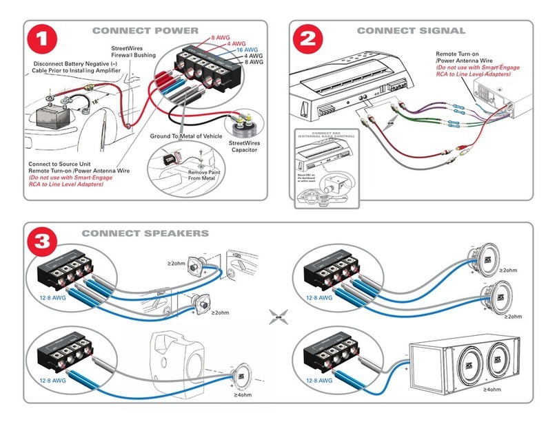
Connect the external remote
control to adjust GAIN level
After all connections are made, connect the positive
terminal to the “+” of the car battery
Connect the negative terminal
to the car body
Connect the line output of your
car head unit with the line input
on the car amplifier with an
interconnect cable
Use the extender cable of the
remote control to connect
with the car amplifier
Speaker terminals to connect car speakers
Car amplifier turn-on control wire. Connect this terminal
to the corresponding wire on the head unit. The terminal
can also be connected to a car antenna resistor. Another
way is to connect the turn-on control wire to the car ignition
10

Below you can see the connection diagram with external connection of a signal source;
C O N N E C T I O N D I A G R A M
O F 4 C H A N N E L A M P L I F I E R
After all connections are made, connect the positive
terminal to the “+” of the car battery
Connect the negative terminal
to the car body
Connect the line output of your
car head unit with the line input
on the car amplifier with an
interconnect cable
Use the extender cable of the
remote control to connect
with the car amplifier
Speaker terminals to connect car speakers
Car amplifier turn-on control wire. Connect this terminal
to the corresponding wire on the head unit. The terminal
can also be connected to a car antenna resistor. Another
way is to connect the turn-on control wire to the car ignition
Connect the external remote
control to adjust GAIN level
11

L O U D S P E A K E R
C O N N E C T I O N S
In 4-channel operation (for example, one loudspeaker on each amplifier channel), the impedance
must not be lower than 2 ohms for each speaker
In bridging mode (two amplifier outputs bridged) the impedance must not be lower than 4 ohms for
the bridged output.
Never connect loudspeaker cables with the ground of the chassis or the +12V DC supply voltage.
If the amplifier is operated with a too low impedance or incorrectly used, the entire sound system
may be damaged. This means a warranty void in such cases.
12

L O U D S P E A K E R C O N N E C T I O N
D I A G R A M S
13

P O S S I B L E L O U D S P E A K E R
C O N N E C T I O N S
SERIES CONNECTION
PARALLEL CONNECTION
SERIES-PARALLEL CONNECTION
14

S U B W O O F E R C O N N E C T I O N
D I A G R A M S
15

S P E C I F I C A T I O N S L M - 2 . 8 0
Number of channels: 2/1
Rated power @ 4 Ohm, STEREO: 80W x 2
Rated power @ 4 ohms, bridged MONO: 260W x 1
Rated power @ 2 ohms, STEREO: 130W x 2
Maximum power @ 40m: 130W х 2
Peak power total: 600W
Frequency Response Range: 10Hz ~ 30 kHz
Harmonic Distortion (THD) @ 1kHz (40m): 0.15%
Low pass filter: 30 - 300 Hz
High pass filter: 30Hz – 8 kHz
Input sensitivity: 200mV-8V
Channel separation: >45 dB
Signal to noise ratio: ≥96dB
Overvoltage / undervoltage protection: > 18 / <9
Bass Boost remote control (0 - 18dB)
Crossover switch: LPF-FULL-HPF
Bass Boost switch (step): 0-6-12 dB
Fuse Rating: 30A
Dimensions, inches: 7.48 x 2.28 x 8.58
16

S P E C I F I C A T I O N S L M - 2 . 1 0 0
Number of channels: 2/1
Rated power @ 4 Ohm, STEREO: 100W x 2
Rated power @ 4 ohms, bridged MONO: 300W x 1
Rated power @ 2 ohms, STEREO: 150W x 2
Maximum power @ 40m: 150W х 2
Peak power total: 700W
Frequency Response Range: 10Hz ~ 30 kHz
Harmonic Distortion (THD) @ 1kHz (40m): 0.15%
Low pass filter: 30 - 300 Hz
High pass filter: 30Hz – 8 kHz
Input sensitivity: 200mV-8V
Channel separation: >45 dB
Signal to noise ratio: ≥96dB
Overvoltage / undervoltage protection: > 18 / <9
Bass Boost remote control (0 - 18dB)
Crossover switch: LPF-FULL-HPF
Bass Boost switch (step): 0-6-12 dB
Fuse Rating: 2x20A
Dimensions, inches: 7.48 x 2.28 x 9.37”
17

S P E C I F I C A T I O N S L M - 4 . 8 0
Number of channels: 4/3/2
Rated power @ 4 Ohm, STEREO: 80W x 4
Rated power @ 4 ohms, bridged MONO: 260W x 2
Rated power @ 2 ohms, STEREO: 130W x 4
Maximum power @ 40m: 130W х 4
Peak power total: 1300W
Frequency Response Range: 10Hz ~ 30 kHz
Harmonic Distortion (THD) @ 1kHz (40m): 0.15%
Low pass filter: 30 - 300 Hz
High pass filter: 30Hz – 8 kHz
Input sensitivity: 200mV-8V
Channel separation: >45 dB
Signal to noise ratio: ≥92dB
Overvoltage / undervoltage protection: > 18 / <9
Bass Boost remote control (0 - 18dB)
Crossover switch: LPF-FULL-HPF
Bass Boost switch (step): 0-6-12 dB
Fuse Rating: 2x20A
Dimensions, inches: 7.48 x 2.28 x 11.73”
18

S P E C I F I C A T I O N S L M - 4 . 1 0 0
Number of channels: 4/3/2
Rated power @ 4 Ohm, STEREO: 100W x 4
Rated power @ 4 ohms, bridged MONO: 300W x 2
Rated power @ 2 ohms, STEREO: 150W x 4
Maximum power @ 40m: 150W х 4
Peak power total: 1500W
Frequency Response Range: 10Hz ~ 30 kHz
Harmonic Distortion (THD) @ 1kHz (40m): 0.15%
Low pass filter: 30 - 300 Hz
High pass filter: 30Hz – 8 kHz
Input sensitivity: 200mV-8V
Channel separation: >45 dB
Signal to noise ratio: ≥92dB
Overvoltage / undervoltage protection: > 18 / <9
Bass Boost remote control (0 - 18dB)
Crossover switch: LPF-FULL-HPF
Bass Boost switch (step): 0-6-12 dB
Fuse Rating: 2x20A
Dimensions, inches: 7.48 x 2.28 x 11.73”
19

T R O U B L E S H O O T I N G
If you are having any trouble after installation, please, follow the Troubleshooting steps/points as
below.
STEP 1:
Check the amplifier for proper connections.
Ensure that PWR/ PRT LED lights up green. If this is the case, skip to point 3, if not continue.
1. Check in-line fuse on battery positive cable. Replace if necessary.
2. Check fuse(s) on amplifier. Replace if necessary.
3. Verify that Ground connection is connected to clean metal on the car's chassis. Repair/replace if
necessary.
4. Ensure there is 12 to 14 Volts present at the positive terminal and remote turn-on cable. Verify quality
connections for both cables at amplifier, car stereo, and battery/fuse holder. Repair/replace if
necessary.
STEP 2:
PWR/PRT LED lights up red.
1. If the PROTECT lights up red, this is a sign of a possible short in the speaker connections. Check for
proper speaker connections and use an ohm meter to check for possible shorts in the speaker wiring.
Too low speaker impedance may also cause PROTECTION to light. This can also be a sign of driving
the amplifier at very high power GAINs without adequate airflow around the amplifier. Shutoff the
system and allow amplifier to cool down. Check that the car charging system is maintaining proper
voltage. If the previous items do not solve the trouble, a fault may be in the amplifier. In this case you
should contact your seller.
STEP 3:
Check the amplifier for audio output.
1. Check good RCA input connections at car stereo and amplifier. Check entire length of cables for
kinks, splices, etc.
Test RCA inputs for AC volts with car stereo on. Repair/replace if necessary.
STEP 4:
Check the amplifier for a popping noise while turning on.
1. Disconnect input signal to amplifier and turn amplifier on and off.
2. If the noise is eliminated, connect the remote lead of amplifier to source unit with a delay turn-on
module.
STEP 5:
Check the amplifier if you experience excess Engine Noise.
1. Route all signal carrying wires (RCA, Speaker cables) away from power and ground wires.
2. Bypass any and all electrical components between the car head unit and the amplifier(s). Connect
the car stereo directly to input of amplifier. If noise stopped the unit being bypassed is the cause of
the noise.
3. Remove existing ground wires for all electrical components. Reroute wires to different locations.
Ensure that grounding location is clean, shiny metal free of paint, rust etc.
4. Add secondary ground cable from negative battery terminal to the chassis metal or engine block
of vehicle.
5. Request assistance of a mechanic to test alternator and battery load. Check good working order
of vehicle electrical system including distributor, spark plugs, voltage regulator, spark plug wires etc.
Please contact with your seller if the amplifier still does not work even after the above
troubleshooting list had been checked.
For warranty adjustment / repairs, the original invoice has to be presented!
Opening or disassembling the amplifier void warranty!
20
This manual suits for next models
3
Table of contents
