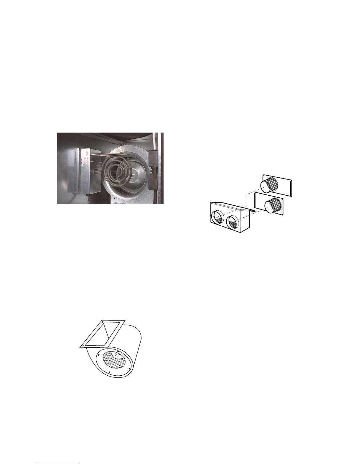
Fig. 7.
Fig. 8.
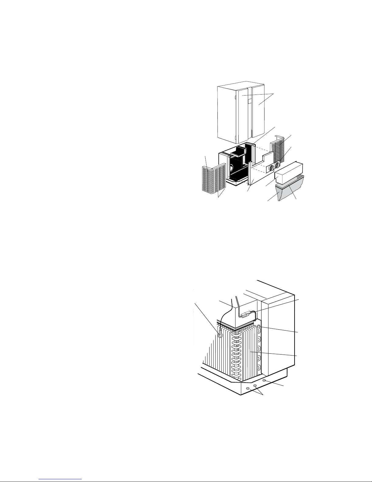
Overheating protection for electrical coil
The coil is equipped with two temperature limiters: one
with automatic resetting, set to 40º C, and an overheating
protector with manual resetting, which trips at 120º C.
Resetting is performed with two buttons on the over-
heating protector positioned on the rear of the dividing
wall on which the coil is located (where the exhaust air
filter is located).
Cleaning of fans
The fans for the ABR room unit are directly driven. Both
fans should be checked and cleaned as required. Wipe the
fan with a cloth. Clean the fan impeller using a vacuum
cleaner fitted with a soft brush nozzle. Take care to clean
all the fan blades, to prevent imbalance arising in the fan.
Dismantling and re-assembly of fan unit
1. Separate the connector for the fan. Note the lock.
2. Remove the electrical heater, if present (applies to
supply air fan).
3. Remove the front two bolts, and lift out the fan unit.
Check the vibration damping when refitting.
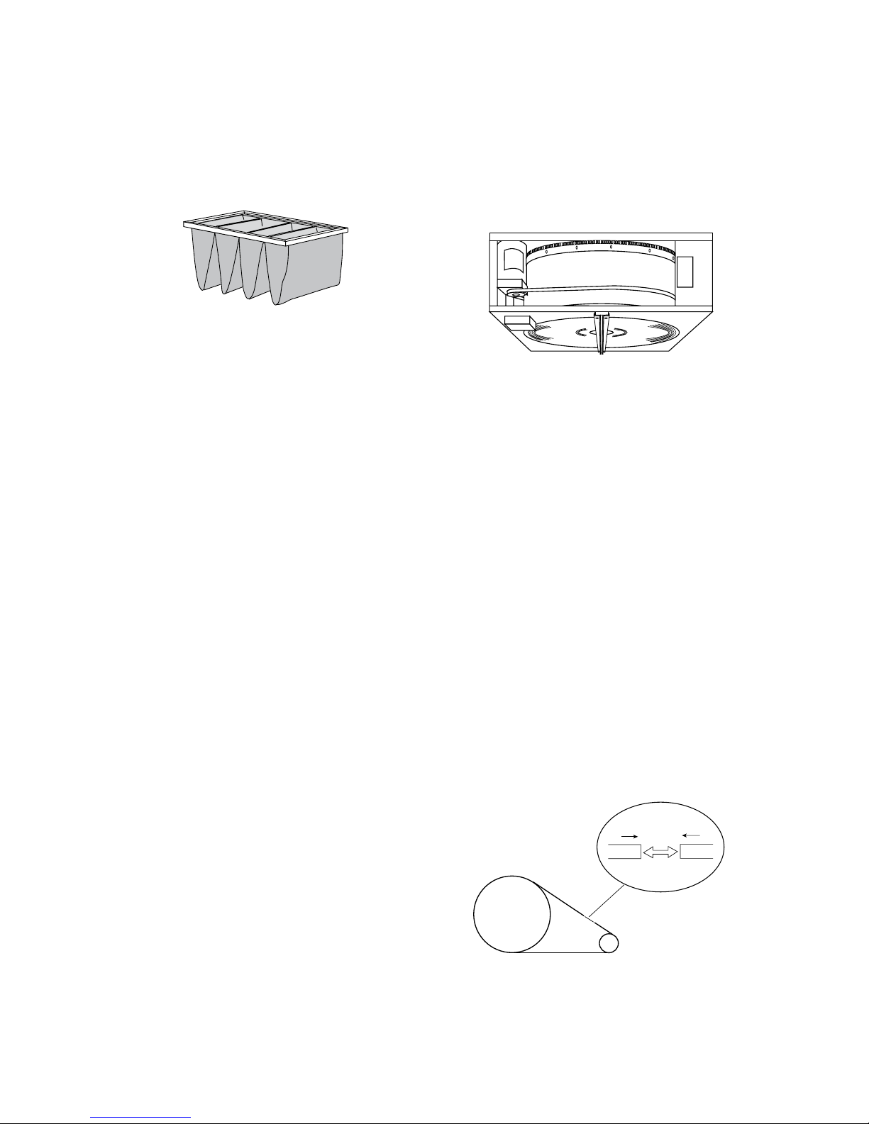
Electrical coil
The electrical coil should be checked and cleaned as re-
quired, since an accumulation of dust can cause odours
and, in the worst case, fire.
If the need arises, the dividing wall complete with the
electrical coil can be pulled out. Allow the coil to cool be-
fore pulling it out and cleaninging it. First disconnect the
connector. Note the lock.
Fig.9.
Replacement of bearings and fan impeller
wheel
The bearings in the fan motor are lubricated at the factory
and maintenance-free.
The entire fan unit must be replaced in the event of
damage. This ensures that high quality, with a balanced
unit, is achieved for the fans.
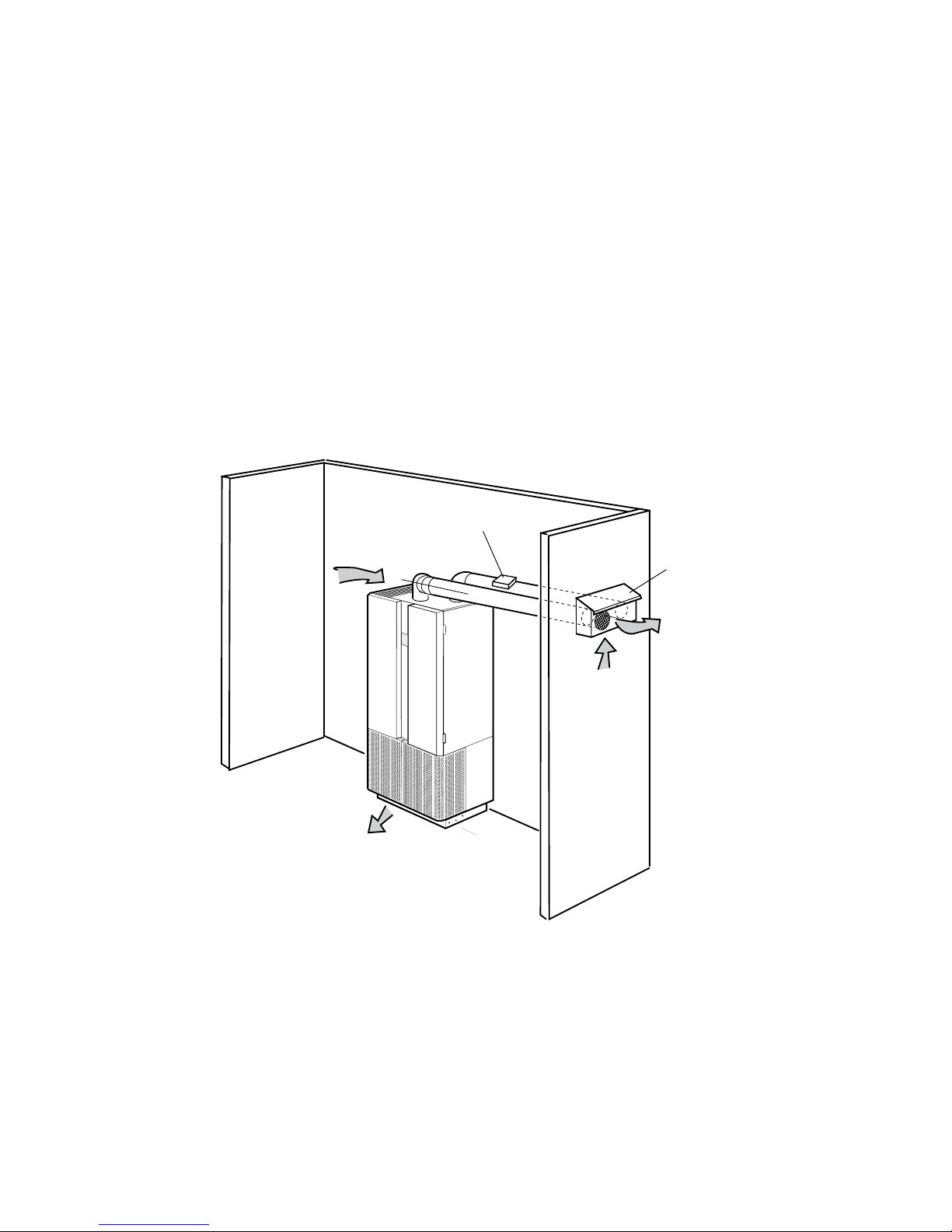
Ducts and combi-hood
The front panel is detachable to allow the connected
ducts to be checked; these should be cleaned, if necessary.
If any other type of supply air and extract air terminal
device is used, the maintenance should be adapted to the
design in question.
Maintenance
Supply air terminal device
The front grille consists of two halves, each of which are
detachable in order to permit the supply air device and
the sound attenuator to be checked and, if necessary,
cleaned.
Vaccum both sides of the supply air device once a
year.
Cleaning of sound attenuator
1. Open the inspection covers, and remove the two bolts
located on the top edge of the front grille.
2. Undo the four bolts (using a 13 mm spanner) located
on the bottom edge of the front grille by approx. two
turns, and pull out and lift off the front grille.
3. If the unit has a cooling coil, fold it forwards; the coil
has flexible hoses for the water connection.
4. Undo the bolts along the edge of the central plate, and
lift out the central plate with the dividing bag.
5. Lift out the terminal device insert.
N.B. On re-assembly, the terminal device insert must be
secured laterally in a groove on the fan outlet on the rear
edge of the terminal device.