Flaman Fitness Progression 200 User manual

200
OWNER’S MANUAL
ASSEMBLYƎOPERATIONƎMAINTENANCE
WARRANTYƎPART ORDERING
▲CAUTION:
Exercise of a strenuous nature, as is customarily done on this equipment, should not
be undertaken without first consulting a physician. No specific health claims are made or implied as
they relate to the equipment.
IMPORTANT:
Read all instructions carefully before using this product. Retain this owner’s
manual for future reference.

CUSTOMER SERVICE 1-866-978-1999 1 FLAMAN SALES LTD. ©2008
TABLE OF CONTENTS
Safety Precautions……………………………………………………… 2
Before you begin……………………………………………………….. 4
Assemb y………………………………………………………………... 5
Operation and adjustment…….………………………………………. 10
Fo ding…………………………………………………………………… 16
Parts ist…………………………............................................................... 17
Overview Drawing………………………………………………………. 14
Troub e Shooting…………………………………………………………. 22
Treadbe t Adjustment…………………………………………………….. 23
Treadmi Lubrication ……………………………………………………. 24
C eaning and Maintenance………………………………………………… 25
Training Guide ines ………………………………………………………. 27
Exercise Routine…………………………………………………………… 30
Warranty…………………………………………………………………. 32
CUSTOMER SERVICE 1-866-978-1999 2 FLAMAN SALES LTD. ©2008
IMPORTANT SAFETY INFORMATION
THIS UNIT IS INTENDED FOR HOUSEHOLD USE ONLY
READ ALL INSTRUCTIONS BEFORE USING THIS TREADMILL
▲CAUTION: Before st rting ny exercise progr m, it is recommended th t you consult your physici n.
▲WARNING: Connect this unit to properly grounded outlet only.
▲DANGER: To reduce the risk of electric shock, lw ys unplug the tre dmill from the electric l outlet
immedi tely fter using nd before cle ning.
WARNING
To reduce the risk of burns, fire, e ectric shock, or injury to persons
:
1. Use 120 volt .c. household current on dedic ted circuit.
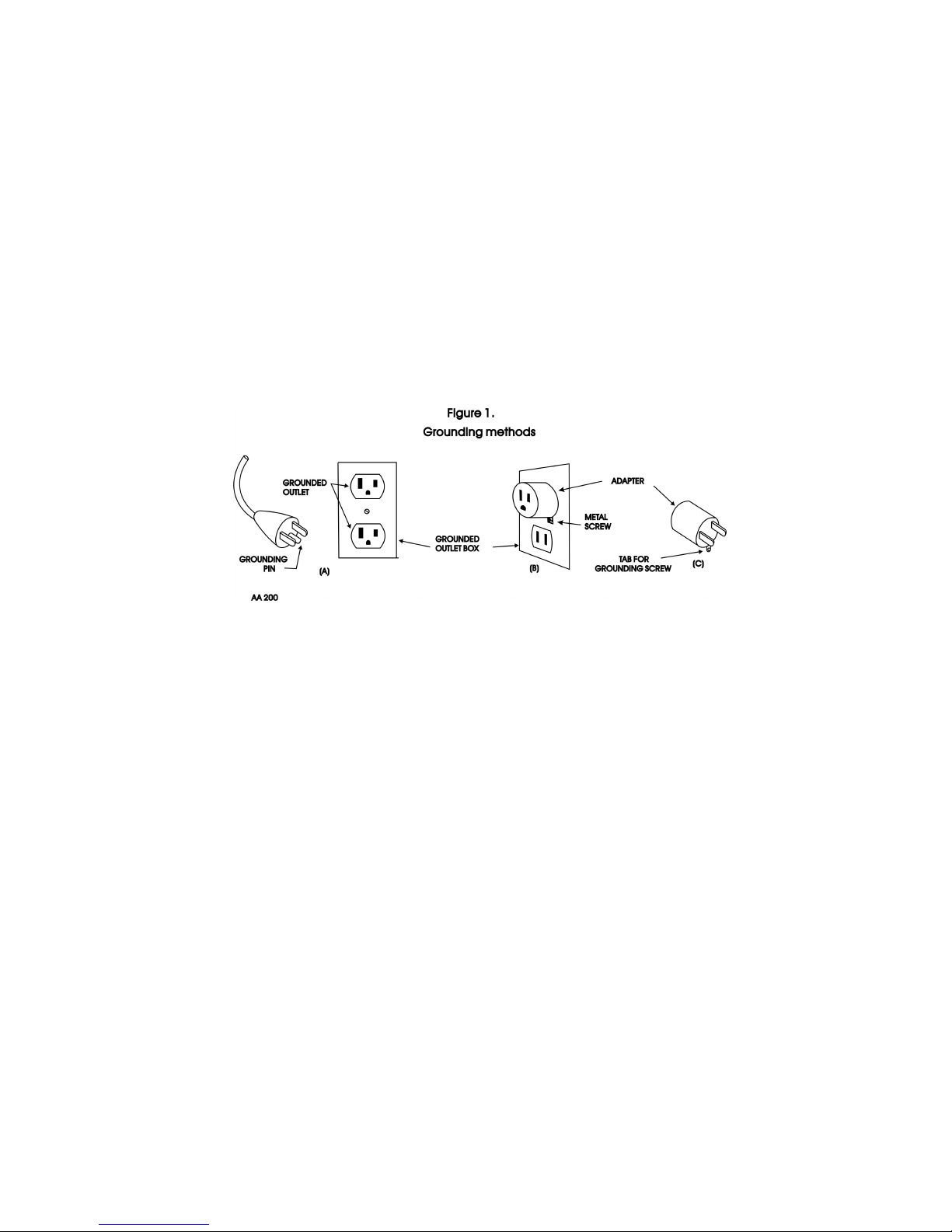
Grounding Instructions
This product must be grounded. If it should m lfunction or bre kdown, grounding provides p th of le st resist nce for
electric current to reduce the risk of electric shock. This product is equipped with cord h ving n equipment-grounding
conductor nd grounding plug. The plug must be plugged into n ppropri te outlet th t is properly inst lled nd grounded
in ccord nce with ll loc l codes nd ordin nces. See di gr m below for grounding methods.
2. It is the responsibility of the owner to ensure th t ll users of this tre dmill re dequ tely informed of ll w rnings
nd prec utions.
3. The use of n extension cord with this product is not recommended. If n extension cord is needed, use short
(less th n 10 feet) he vy g uge (14 g uge or better) extension cord with three prong (grounded) plug nd
recept cle.
4. Never le ve the tre dmill un ttended when plugged in. Remove the s fety key nd unplug the unit from the outlet
when not in use nd before removing or repl cing p rts.
5. Never oper te the tre dmill if it h s d m ged cord or plug, if it is not working properly, if it h s been dropped,
d m ged, or exposed to w ter. Never move the tre dmill belt while the power is turned off.
6. Do not pull the tre dmill by the power supply cord or use cord s h ndle. Keep cord w y from he ted surf ces
nd open fl mes.
7. Fitness equipment must lw ys be inst lled nd used on fl t surf ce. Do not use outdoors or ne r w ter. Do not
pl ce the unit on loose rug or uneven surf ce. It is recommended to use n equipment m t to prevent the unit
from moving while it is being used, which could possibly scr tch or d m ge the surf ce of your floor. It is
recommended to h ve minimum of 3 metres s fe cle r nce on ll sides of the tre dmill while in use.
8. Keep the tre dmill indoors, w y from moisture nd dust. Do not put the tre dmill in g r ge, covered p tio or
ne r w ter.
9. Do not oper te the tre dmill where erosol products re used or where oxygen is being dministered.
10. Re d, underst nd nd test the emergency stop procedure before using the tre dmill (see oper tion nd djustment
on p ge 8)
11. Do not insert ny objects into ny openings.
12. Inspect nd properly tighten ll p rts of the tre dmill regul rly.
13. Keep children nd pets w y from this equipment t ll times while exercising.
14.H ndic pped individu ls should h ve medic l pprov l nd close supervision when using this tre dmill.
15. Do not pl ce h nds or feet under the tre dmill. Alw ys keep h nds nd legs off of the tre dmill when others re
using it.

CUSTOMER SERVICE 1-866-978-1999 3 FLAMAN SALES LTD. ©2008
16. Never turn on tre dmill while st nding on tre dbelt. Alw ys hold the h ndr ils while using the tre dmill. Alw ys
return the tre dmill to the slowest speed to provide for s fe dismount nd low speed rest rt.
17. To disconnect, turn ll controls to the off position, then remove plug from outlet.
18.Do not ttempt to r ise, lower or move the tre dmill until it is properly ssembled. See ssembly on p ge 5 nd to
fold nd move the tre dmill on p ge 11. C re must be t ken when lifting or moving the equipment, so s not to
injure your b ck. Alw ys use proper lifting techniques. You must use ny tt chments th t re not recommended
by the m nuf cturer.
19. Use the tre dmill only for its intended use s described in this m nu l. Do not use ny tt chments th t re not
recommended by the m nuf cturer.
20. User weight should not exceed 300 (135kg).
21. Never llow more th n one person on the tre dmill t once.
22. W rm up 5 to 10 minutes before e ch workout nd cool down 5 to 10 minutes fterw rd. This llows your he rt
r te to gr du lly incre se nd decre se nd will help prevent str ining muscles.
23. Never hold your bre th while exercising. Bre thing should rem in t norm l r te in conjunction with the level of
exercise being performed.
24. St rt your progr m slowly nd very gr du lly incre se your speed nd dist nce.
25. Alw ys we r suit ble clothing nd footwe r while exercising. Do not we r loose fitting clothing th t could
become ent ngled with the moving p rts of your tre dmill. Do not w lk or jog b refoot, in stocking feet or loose
fitting shoes or slippers.
26. This tre dmill is intended for in-home use only. Do not use the tre dmill in ny commerci l, rent l or institution l
setting.
▲WARNING: Before beginning ny exercise progr m consult your physici n. This is especi lly import nt for
individu ls over the ge of 35 or persons with pre-existing he lth problems. Re d ll instructions before using ny fitness
equipment. We ssume no responsibility from person l injury or property d m ge sust ined by or through the use of this
product.
SAVE THESE INSTRUCTIONS
CUSTOMER SERVICE 1-866-978-1999 4 FLAMAN SALES LTD. ©2008
Before you begin.
Th nk you for purch sing our product. Even though we go to gre t efforts to ensure the qu lity of e ch product
we produce, occ sion l errors nd /or omissions do occur. In ny event should you find this product to h ve
either defective or missing p rt ple se cont ct us for repl cement.
This product h s been designed for home use only. Product li bility nd gu r ntee conditions will not be
pplic ble to products being subjected to profession l use or products being used in gym center.
This exercise equipment w s designed nd built for optimum s fety. However, cert in prec utions pply
whenever you oper te piece of exercise equipment. Be sure to read the entire manua before assemb y and
operation of this machine.
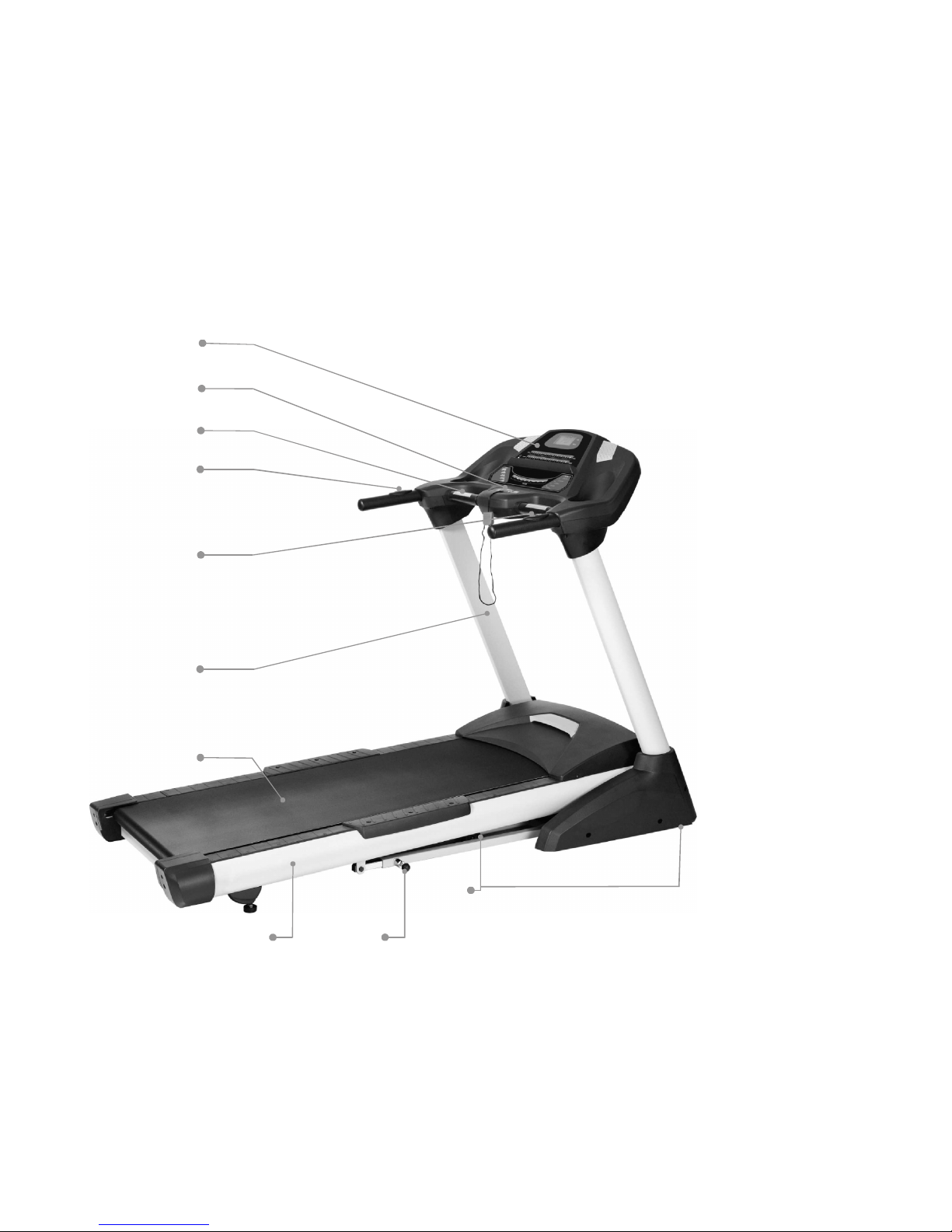
Before re ding further, ple se f mili rize yourself with the p rts th t re l beled in the dr wing below.
MAX. USER WEIGHT LIMIT 135 KGS (300 LBS)
S fety Key
H ndgrip tube
H ndpulse
Locking Knob
Console
Upright
M in fr me
W lking belt
Wheel
Book R ck
Circuit bre ker
On / off switch
Motor cover
Foot r il
Adjustment bolts
W lking belt
Speed djusting switch
Incline djusting switch

CUSTOMER SERVICE 1-866-978-1999 5 FLAMAN SALES LTD. ©2008
HARDWARE CHECK LIST
#94. 5/16” x15m/m
Button He d Socket Bolt (14pcs)
#102. S fety Key (1pc)
#93 Lubric nt (1pc)
#96. M5 x 10 m/m
Phillips He d Screw (6pcs)
#95.5/16”x19x1.5T Curved W sher
(8pcs)
#98 M6 Allen Wrench (1pc)
##97. Combin tion M5 Allen Wrench &
Phillips He d Screw Driver (1 pc)
#90. 3.5x12 m/m
Self T pping Screw (4pcs)

CUSTOMER SERVICE 1-866-978-1999 6 FLAMAN SALES LTD. ©2008
ASSEMBLY INSTRUCTION
I
t will t ke two people to ssemble your unit.
Set the tre dmill in cle red re nd remove ll p cking m teri l. Do not dispose of the m teri l until
your ssembly is completed. Note: The underside of your tre dmill’s w lking belt is co ted with
lubric nt. During shipping, sm ll mount of lubric nt m y be tr nsferred to the top of the w ling belt
or the shipping c rton. This does not ffect the tre dmill’s perform nce. If you notice ny lubric nt on
the top of the w lking belt, simply wipe off the lubric nt with soft cloth nd mild, non br sive
cle ner.
For the s ke of f mili rizing yourself with the p rts identified in the instructions, first study the
overview dr wing.
Assembly only requires the included wrenches.
Step 1.
Remove the tre dmill from the c rton nd l y it on smooth level surf ce.
Step2.
Connect the Lower Computer C ble (38) to the Extension Computer C ble (37).
38
37

CUSTOMER SERVICE 1-866-978-1999 7 FLAMAN SALES LTD. ©2008
Step 3
Secure the right nd left Upright (4,5) into the Fr me B se with the 8pcs of 5/16”x15m/m Button He d Socket Bolts
(94) nd 4 pcs of 5/16" x 19 x 1.5T Curved W shers (95). Be c reful not to pinch the computer c ble when
inst lling the Right Upright.
97 95
94
94
94
94
95
Step 4.
Inst ll the Left Upright Cover (41) onto the Left Upright (4) nd the Right Upright Cover (40) onto the Right Upright
(5). Ensure th t the covers re f cing the correct direction nd llow them to slide down nd sit t the bottom of the
uprights.
41
4
40
5

CUSTOMER SERVICE 1-866-978-1999 8 FLAMAN SALES LTD. ©2008
Step 5.
Connect the Extension Computer C ble (37) with the Upper Computer C ble (36).
37
36
Step 6.
Secure the Console Assembly (39) into the Left & Right Uprights (4,5) with the 6pcs of 5/16”x15m/m Button He d
Socket Bolts (94) nd 4 pcs of 5/16" x 19 x 1.5T Curved W shers (95).
94
95
4
94
94
97
39
5
94
95

CUSTOMER SERVICE 1-866-978-1999 9 FLAMAN SALES LTD. ©2008
Step 7.
Secure the Left nd Right Upright Covers (41, 40) to the Console Assembly (39) with the 4 pcs of 3.5x12m/m Self
T pping Screws (90).
39
41 40
90
97
90
Step 8.
Inst ll the Fr me B se C ps (44,43) onto the Fr me B se. Secure with 6pcs of M5x10m/m Phillips He d Screws (96).
96
44
97
43
96
NOTE: Ensure th t ll nuts nd bolts re tightned.

CUSTOMER SERVICE 1-866-978-1999 10 FLAMAN SALES LTD. ©2008
TREADMILL OPERATION
Your tre dmill fe tures w lking belt co ted with lubric nt. IMPORTANT: Never pply silicone
spr y or other subst nces to the w lking belt or w lking bo rd. Such subst nces will deterior te the
w lking belt nd c use excessive we r.
How to p ug in the power cord.
GROUNDING INSTRUCTIONS.
This product must be grounded. No plug d pter should be used with this product.
▲WARNING: Improper connection of the equipment grounding conductor c n result in risk of n
electric shock. Check with qu lified electrici n if you re in doubt s to whether the product is
properly grounded. Do not modify the plug provided with the product, if it will not fit the outlet; h ve
proper outlet inst lled by qu lified electrici n. The use of n extension cord with this product is not
recommended. If n extension cord is needed, use short (less th n 10 feet) he vy g uge (14 g uge or
better) extension cord with three prong (grounded) plug nd recept cle. IMPORTANT: If the power
cord is d m ged, it must be repl ced with m nuf cturer recommended power cord.
1. Plug the indic ted end of the power cord into the socket of the tre dmill. See dr wing below
2. Plug the power cord into n ppropri te outlet th t is properly inst lled nd gounded. See
dr wing below. Import nt: The tre dmill is not comp tible with GFCI-equipped outlets.
Note: Your power cord and outlet may appear different.

CUSTOMER SERVICE 1-866-978-1999 11 FLAMAN SALES LTD. ©2008
MONITOR INSTRUCTIONS
▲CAUTION: Before oper ting the console, re d the following prec utions:
• Do not st nd on the w lking belt when turning on the tre dmill
• Alw ys we r the s fety key
• Adjust the speed in sm ll increments to void sudden jumps in speed
• To reduce the possibility of electric shock, keep the console dry. Avoid spilling liquids on the
console nd pl ce only se led w ter bottles in the w ter bottle holders.
TO OPERATE TREADMILL
▲CAUTION: To void injury, hold onto the h ndr ils while mounting nd dismounting the tre dmill.
Hold onto the h ndr ils nd pl ce feet on sider ils before st rting. Step onto the w lking belt only
slowest speed.
Before oper ting the console m ke sure th t the power cord is properly plugged in nd the on / off
button is on.
1. Hold onto h ndr il nd pl ce feet on sider ils before st rting tre dmill. (Do not st nd on
tre dbelt).
2. Att ch the m gnet end of the s fety key onto the monitor nd tt ch the clip end of the s fety key
to your clothing (ie: w istb nd). If you should slip or f ll while exercising the s fety key will pull
out of the console, shutting off the tre dmill.
Choose which progr m you w nt to select, m nu l (P0) or pre-set (p1-p5).
Initia Disp ay:
When the power is turned on, the m in displ y will light up showing ll ch r cters. The console will
be performing n intern l test to m ke sure the console is oper tion l. The displ y will then scroll
through three numbers, the first showing the current softw re version, second is how m ny hours the
tre dmill h s been in use nd third is how m ny virtu l miles the tre dmill h s gone. The tre dmill
will then enter idle mode nd show P0 on the displ y, which is the st rting point for oper tion.

CUSTOMER SERVICE 1-866-978-1999 12 FLAMAN SALES LTD. ©2008
WINDOW DISPLAY DATA:
SCAN: When lit, will sc n through ll the displ y inform tion; e ch one for 5 seconds.
SPEED: Displ ys the current belt speed from st rting t 1.0Mph to 10.0Mph.
TIME: Accumul tes tot l workout time from 00:00 to 99:59.
DISTANCE: Accumul tes tot l workout dist nce from 0.00 to 99.99 miles.
CALORIES: Accumul tes the user’s c lorie consumption during exercise. M x. V lue is 9999
c lories.
PULSE: Displ ys your current he rt r te in be ts per minute from 40 to 240.
♥
♥♥
♥ Icon: The he rt icon blinks when pulse is detected.
INCLINE LED: When lit, the displ y will be showing the elev tion position from 0 to 10.
LUBE LED: Reminds the user to pply silicon lubric nt between the belt nd deck. To turn
off the light press nd hold the SELECT button for 5 seconds.
FUNCTION BUTTON:
START: Press “START” button to st rt tr ining.
STOP: Press “STOP” button to stop tr ining nd press for 3 seconds to reset.
FAST: Press “FAST’ button to incre se your speed.
SLOW: Press “SLOW” button to decre se your speed.
UP: Press “UP” button to incre se elev tion position.
DOWN: Press “DOWN” button to decre se elev tion position.
ENTER: Press “ENTER” button to select different setting p r meters in STOP mode.
SELECT: Press “SELECT” button to scroll through the displ y workout inform tion.
PROGRAM UP/DOWN: Press PROGRAMUP/DOWN buttons to scroll through workout progr ms.
RAPID SPEED KEYS: 10 preset speed buttons to jump to desired speed quickly. You c n lso
press the ny of the 10 buttons to st rt tre dmill from the st rt-up screen.
The tre dmill will utom tic lly st rt nd slowly incre se speed to the
preset number.
RAPID INCLINE KEYS: 10 preset incline buttons to jump to desired incline setting quickly.

CUSTOMER SERVICE 1-866-978-1999 13 FLAMAN SALES LTD. ©2008
Quick-Start Operation:
STEP 1: Att ch the S fety key to w ke displ y up (if not lre dy on). The m in window will
show the initi l displ y: P0.
STEP 2: Press the START button to begin belt movement fter three second count down. Use
the FAST/SLOW keys to djust the desired speed (on console) t ny time during
tr ining. Using the UP/DOWN keys to djust the Incline t ny time during tr ining.
To set the time to count down, see STEP 7.
STEP 3: Press the SELECT button to scroll through your workout d t . The initi l screen will
be showing the SPEED. Pressing the SELECT button will show the TIME then
DISTANCE, CALORIES, PULSE, INCLINE nd SCAN. In sc n mode e ch d t will
be displ yed for 5 seconds.
STEP 4: To get pulse re ding, simply gr sp both st inless steel pick-ups. M ke sure the
displ y is set to show Pulse, or Sc n. When the ♥ Icon is fl shing th t me ns the
console is receiving pulse. It m y t ke few seconds for the displ y to re ch the
ctu l number.
STEP 5: While tr ining, you c n press STOP button to stop your workout or pull s fety key
w y from its position to shut down the computer. If you w nt to resume your
workout, you c n press START button nd ll previous d t will resume counting.
STEP 6: At the end of progr m you c n press FAST/SLOW to displ y the ccumul ted d t
for speed, time, dist nce nd c lories th t re memorized during tr ining.
STEP 7: To set TARGET: Before tr ining, press the ENTER button to be ble to progr m the
time clock to count down. Use the up nd down keys to set the time then press St rt or
Enter to progr m the Dist nce or C lories. If you set multiple p r meters, the first one
to re ch zero ends the progr m.

CUSTOMER SERVICE 1-866-978-1999 14 FLAMAN SALES LTD. ©2008
To Se ect a Program:
Step 1: Press the ^ or v button to choose P1 ~ P5, e ch progr m h s preset speed v lue.
Step 2: Press the ENTER button to set the count down time from 10:00 to 99:00; the preset v lue
is 20:00. You c n djust the v lue by pressing FAST/SLOW or press START button to
st rt tr ining immedi tely.
Step 3: Press STOP button to stop your workout or pull s fety key w y from its position to shut
down the computer.
Pu se Feature:
The Pulse (He rt R te) window will displ y your current he rt r te in be ts per minute during the
workout. You must use both st inless steel sensors on the front cross b r to displ y your pulse. Pulse
v lue displ ys nytime the upper displ y is receiving Pulse sign l.
Optional eature:
There is an Audio Input Jack on the front of the console and built in speakers. You may plug any low
level audio source signal into this port. Audio sources include MP3, Ipod, portable radio, CD player
or even a TV or computer audio signal.
ERROR MESSAGE:
1. LS: Tre dmill doesn’t receive the speed sign l for 8 seconds.
2. E1: Memory of console m lfunction or CPU ccessing problem.
3. Err: Incline position error.

CUSTOMER SERVICE 1-866-978-1999 15 FLAMAN SALES LTD. ©2008
SPEED PROFILE
SPEED PROFILE SPEED PROFILE
SPEED PROFILE
P.1
INCLINE PROFILE
INCLINE PROFILE INCLINE PROFILE
INCLINE PROFILE
P.1
P.2
P.2
P.3
P.3
P.4
P.4
P.5
P.5

CUSTOMER SERVICE 1-866-978-1999 16 FLAMAN SALES LTD. ©2008
FOLDING AND MOVING YOUR TREADMILL
Before folding the tre dmill, ensure th t the tre dmill is t its lowest incline position. Turn the power
switch off, loc ted on the front of the motor cover nd unplug the power cord.
CAUTION: You must be ble to s fely lift 20 kg (45lbs) in order to r ise nd lower the tre dmill.
To decre se the possibility of injury, bend your legs nd keep your b ck str ight while
you re r ising or lowering your tre dmill.
To protect the floor or c rpet from d m ge, pl ce m t under the tre dmill. Keep the tre dmill out of
direct sunlight. Do not le ve the tre dmill in the stor ge position in temper tures bove 85 degrees
F hrenheit.
Unfo ding
Hold the tre dmill running deck with left h nd. Pull the locking knob with your right h nd nd slowly
lower the tre dmill running deck. The deck will lower un ssisted when it re ches bout w ist high.
Fo ding
Lift the tre dmill running deck with your left h nd. Pull the locking knob with your right h nd nd
slowly r ise the tre dmill running deck until the tre dmill is locked by the locking knob.
Moving
Before moving the tre dmill, fold the tre dmill to the stored position s described bove.
Hold the
h ndgrip tubes nd c refully move the tre dmill to your desired loc tion.
To reduce the risk of injury, use extreme c ution while moving the tre dmill, do not ttempt to move the
tre dmill over n uneven surf ce.

CUSTOMER SERVICE 1-866-978-1999 17 FLAMAN SALES LTD. ©2008
KEY NO.
PART NO.
DESCRIPTION O'TY
1 020001 M in Fr me 1
2 020002 Fr me B se 1
3 020003 Incline Br cket 1
4 020004 Left H ndr il 1
5 020005 Right H ndr il 1
6 020006 Console Support 1
7 020007 Outer Slide 1
8 020008 Inner Slide 1
9 0200009 Locking Knob Axle
1
10 020010 Bottom Motor Pl te 1
11 020011 Belt Guide 2
12 020012 Running Deck 1
13 020013 Running Belt 1
14 020014 Drive Belt 1
15 020015 Front Roller W/Pulley 1
16 020016 Re r Roller 1
17 020017 Wheel Sleeve 2
18 020018 M gnet 2
19 020019 Cylinder 1
20 020020 H ndgrip Fo m 2
21 020021 Wire Tie Mount 5
22 020022 Motor 1
23 020023 Incline Motor 1
24 020024 Controller 1
25 020025 Speed Adjustment Switch W/C ble 1
26 020026 Incline Adjustment Switch W/C ble 1
27 020027 H ndpulse W/C ble Assembly 2
27~1 020027-1 H ndpulse Wire, Coiled 1
27~3 020027-3 H ndpulse Assembly Top 2
27~4 020027-4 H ndpulse Assembly Bottom 2
28 020028 Bre ker 1
29 020029 Power Socket
1
30 020030 On/Off Switch
1
31 020031 Sensor W/C ble 1
32 020032 Power Cord 1
33 020033 200m/m x 764 x 764_Connecting Wires (White) 1
34 020034 200m/m x 764 x 764_Connecting Wires (Bl ck) 1
35 020035 100m/m x 764 x 764_Connecting Wires (Bl ck)
1
36 020036 Computer C ble (Upper) 1
37 020037 Computer C ble (Middle) 1
38 020038 Computer C ble (Lower) 1
39 020039 Console Assembly 1
39~1 020039-1 Top Console Cover 1
39~2 020039-2 Bottom Console Cover 1
39~3 020039-3 Inner Console Cover 1
39~4 020039-4 Console Spe ker Cover (R) 1
39~5 020039-5 Console Spe ker Cover (L) 1
39~8 020039-8 Spe ker Grill Anchor 6

CUSTOMER SERVICE 1-866-978-1999 18 FLAMAN SALES LTD. ©2008
KEY NO.
PART NO.
DESCRIPTION O'TY
39~13 020039-13 Amplifier 1
39~14 020039-14 Power Cord Of Amplifier 1
39~15 020039-15 300mm_Spe ker 1
39~16 020039-16 750mm_Spe ker 1
39~17 020039-17 Sound Bo rd 1
39~18 020039-18 Sound Bo rd W/C ble 1
39~19 020039-19 S fety Switch Module W/C ble 1
39~21 020039-21 3×10mm_Self T pping Screw 14
40 020040 Right H ndr il Cover 1
41 020041 Left H ndr il Cover 1
42 020042 38 _Button He d End C p2
43 020043 Fr me B se C p (R) 1
44 020044 Fr me B se C p (L) 1
45 020045 Front Tr nsport tion Wheel 2
46 020046 Re r Tr nsport tion Wheel 2
47 020047 Motor Cover Anchor 2
48 020048 Top Motor Cover 1
49 020049 Top Motor Cover Pl te 1
50 020050 Front Motor Cover 1
51 020051 Foot R il (L) 1
52 020052 Foot R il (R) 1
53 020053 Front Foot R il 4
54 020054 Re r Foot R il 2
55 020055 Re r Adjustment B se (L) 1
56 020056 Re r Adjustment B se (R) 1
57 020057 Foot P d C p 2
58 020058 Cushion 6
59 020059 Foot P d 2
60 020060 Sensor R ck 1
61 020061 10 x 24 x 3T _Nylon W sher (A)3
62 020062 50 x 13 x 3T _Nylon W sher (B)4
63 020063 1/2" x 1-1/4"_C rri ge Bolt 2
64 020064 1/2" x 1"_Hex He d Bolt 2
65 020065 3/8" x 4"_Hex He d Bolt 1
66 020066 3/8" x92m/m_Hex He d Bolt 1
67 020067 3/8" x 3/4" _Hex He d Bolt 4
68 020068 3/8" x 1-1/2" _Hex He d Bolt 1
69 020069 3/8" x 45m/m _Hex He d Bolt 1
70 020070 3/8" x 2-1/2"_Thumb He d Socket Bolt 2
71 020071 5/16" x 1"_Button He d Socket Bolt 4
72 020072 M8 x 60m/m _Hex He d Bolt 1
73 020073 M8 x 65m/m_Socket He d C p Bolt 2
74 020074 M8 x 25m/m_Fl t He d Countersink Screw 8
75 020075 1/2" x 8T_Nyloc Nut 4
76 020076 3/8" x 7T_Nyloc Nut 6
77 020077 5/16" x 6T_Nyloc Nut 2
78 020078 M8 x 8T_Nyloc Nut 1
79 020079 3/8" x 7T_Nut 3
80 020080 35 x 5/16" x 1.5T_Fl t W sher2
81 020081 25 x 10 x 2.0T_Fl t W sher4

CUSTOMER SERVICE 1-866-978-1999 19 FLAMAN SALES LTD. ©2008
KEY NO.
PART NO.
DESCRIPTION O'TY
82 020082 19 x 10 x 1.5T_Fl t W sher 6
83 020083 3/8"×2.0T_Split W sher 4
84 020084 5×15×1.0T_Fl t W sher4
85 020085 M5_R ised W sher 3
86 020086 4x12m/m_Self T pping Screw 4
87 020087 5x16m/m_T pping Screw 32
88 020088 5x19m/m_T pping Screw 7
89 020089 5x16m/m_T pping Screw 8
90 020090 3.5x12m/m_Self T pping Screw 13
91 020091 4x38m/m_Self T pping Screw 2
92 020092 3.5x16m/m_T pping Screw 5
93 020093 Lubric nt 1
94 020094 5/16" x 15m/m_Button He d Socket Bolt 14
95 020095 5/16" x 19 x 1.5T_Curved W sher8
96 020096 M5×10mm_Phillips He d Screw 6
97 020097 Combin tion M5 Allen Wrench & Phillips He d Screw Driver 1
98 020098 M6_Combin tion M6 Allen Wrench & Phillips He d Screw Driver 1
99 020099 3/8"×2"_Hex He d Bolt 1
100 0200100 3×10mm_T pping Screw 4
101 0200101 5×19mm_T pping Screw 20
102 0200102 Tr pezoid l S fety Key 1
106 0200106 21.4×21.4_Squ re End C p1
107 0200107 25.4×25.4_Squ re End C p1
108 0200108 Top Console Cover Anchor 2
109 0200109 3×10mm_Self T pping Screw 2
110 0200110 3.5×12mm_Self T pping Screw 12
111 0200111 13×26×2.0T_Fl t W sher4
112 0200112 1
Table of contents
Popular Treadmill manuals by other brands

GREEN SERIES FITNESS
GREEN SERIES FITNESS CIR-TM6000DC-G Service manual

Tunturi
Tunturi J 440 owner's manual

Horizon Fitness
Horizon Fitness Horizon Series user guide

NordicTrack
NordicTrack Viewpoint 3600 Treadmill user manual

NordicTrack
NordicTrack C2100 Treadmill user manual

Weslo
Weslo Cadence A 40 Treadmill user manual

NordicTrack
NordicTrack NCTL19920 user manual

NordicTrack
NordicTrack 24928.0 user manual

Trojan
Trojan IRON MAN 500 Care instructions and assembly manual

Horizon Fitness
Horizon Fitness Adventure 4 Plus owner's manual
TreadTracker
TreadTracker PFTK001 instruction manual

Rogerblack Fitness
Rogerblack Fitness 330/4947 Assembly & user instructions


