www.GreenSeriesFitness.com ©May 2015 Call Toll free (800) 269-7140
CIR-TM6000DC-G Revision 1.1
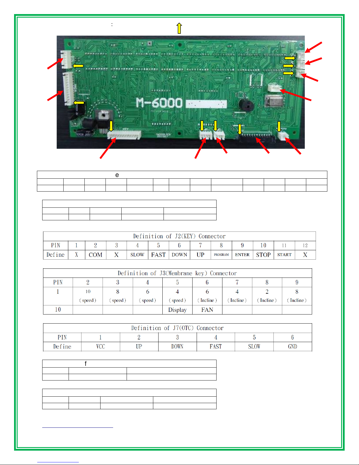
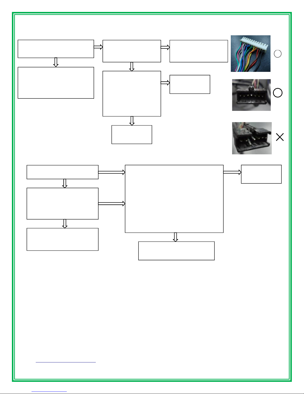
2.2.
【
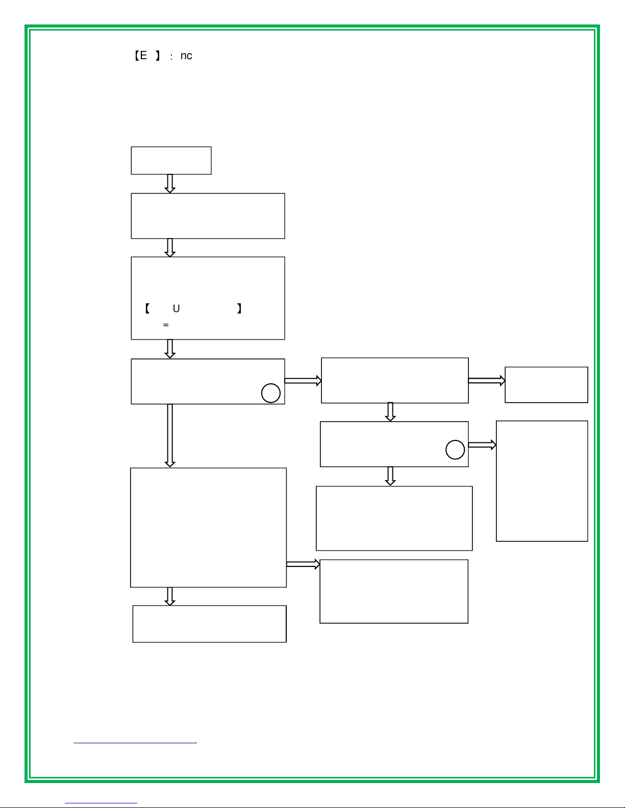
Err
】:
Incline cannot reach the right position, incline function cannot be use but other
functions are normal to use.
*If this is a new product that has just finished being assembled, there is a possibility of
problems in assembly. Check the wire connections and confirm that the wires and cables
have not been damaged during assembly.
Determine Cause and Solution:
Remark A: Before installing a new incline motor or Variable Resistor (VR), be sure to have the
incline level set to zero ( 0 ).
Showing ERR
Turn OFF the AC power and
wait for 10 seconds and then
Pull out the safety key, press
STOP and UP to enter the
engineering mode, displays
【
MANUAL INC XXX
】
(XXX=Incline parameter)
Did the incline move while
pressing the incline UP or
Did the D5 or D6 lamps
illuminate while pressing the
Replace the
console PCB
Check the surface
temperature of the incline
Strip the incline
motor down to
check for
movement
obstructions or
jamming. If the
incline motor is
good, replace the
motor controller.
Wait for cool down and then
repeat step A. If the incline
motor does not work after the
cool down, proceed to step B.
Did the incline motor move
and the incline parameter
change while pressing the
incline UP and DOWN key.
(Parameter range is from the
lowest to highest position, 15
to 195. Check this value
range. Incline motor faulty. Replace
the incline motor or the
variable resistor (VR).
(Remark A)
Incline motor is good. Press
STOP to go back to idle state.