FLEET HOSTER RTR01-1000 User manual

Router RTR01-1000
Installation
Guide

Installation Guide
RTR01-1000
In the Box:
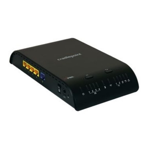
RTR01-1000 Series Mobile Router
This router is rated for mobile/in-vehicle use, but is NOT rated for
water and dust ingress. Proper, secure installation within dry
environments is required. All cabling and connection points
exposed to wet outdoor conditions must be sealed for protection.
Improper installation methods, locations, and use of non-standard
accessories may void your warranty.
What you will need:
Tools- You may need a manual or electric screwdriver or other
fastening tools for your mounting hardware as well as any
Personal Protection Equipment as required by your company or
for general safety.
Mounting hardware- It is recommended to use the proper
mounting screws or other hardware necessary to secure the
router into position. You can use nuts/bolts, self-tapping screws,
zip ties, 2-sided adhesive tape, Velcro, or other hardware to fasten
the router to the surface, based on the surface and requirements
for that surface and being cautious of potential hazards or risks.
Power supply- The router is supplied as a base component only
and requires a power supply, of which there are several options
available. Using alternate power supplies may affect your product
warranty, so please use only the recommended options. Common
options are the fused 12v power cable, AC power cable, or DC
vehicle cigarette lighter cable.
Auxiliary connection cables- In order to connect the router to your
Auxiliary camera hardware, you’ll need the correct Cat6 Ethernet
cable for the RTR01-1000 unit. These are available in varying
lengths and should always be installed securely, with the
connections protected from liquid intrusion. You can also use RJ45
to 4-pin cables when attaching the RTR01-1000 to 4-pin
connectors of auxiliary cameras.

Installation Guide
RTR01-1000
Installing the RTR01-1000:
Take note of the SSID, MAC ID, and Password printed on the back of the
router prior to installation. You will need this for the last step of the
installation.
The closer you can install your router to the primary camera, the better
your connectivity reliability will be. Choose an ideal mounting location that
allows proper safety and operation of the motor vehicle or asset and fasten
the router into place.
Connecting power:
Use either of the recommended power supply cables for powering the
router. The router requires a 12v power supply for connection to fuse-
protected 12v (+) ACC power.
(Use ACC/or power source that is only active while the vehicle is powered
on to avoid battery drainage)
Auxiliary cameras also require 12v (+) ACC power and both the router and
auxiliary cameras require proper (-) grounding to chassis or negative
battery terminal.
The 12v fused power cable comes standard with a Molex style connector
on the power end and a barrel style connector for the router end. Securely
connect the barrel connector to the connection point labeled “DC” on the
rear side of the router and ensure it is properly seated in place. The molex
end of the cable can be connected to an “IoX-AuxM” peripheral connector
(sold separately) for powering through your telematics device. You can also
remove or cut off the Molex adaptor for using the 2-wire connection
method. The Red wire should be connected to 12v(+) ACC power source
while the Black wire should connect to chassis ground/negative source(-).
AC adaptors or DC cigarette style adaptors are available for purchase, and
can be plugged into the proper outlet directly instead of using the Molex
style connection options.
12v fused
power supply cable
Barrel style
connector end
Molex style
connector end
(remove molex
connector for
2-wire option)

Removing the 3 Philips
head screws from the
outer protective shroud
of the auxiliary camera
will expose the primary
mounting plate and
camera angle adjustment
screws. This allows for
proper fastening to your
surface. Please reinstall
the shroud when
fastening is complete.

Installation Guide
RTR01-1000
Router connection diagram
Connect the auxiliary camera(s) to the router using weather-rated high speed ethernet cables of
appropriate length. Each auxiliary camera should be connected directly to the router with the proper
cable. Ensure that connection points are sealed to prevent water intrusion and protected from
potential marring or damage. When connecting the ethernet cable to the auxiliary camera, please be
sure to utilize the provided RJ45 weather resistant connector cap, which will provide water ingress
resistance for the cable connection. Insert the auxiliary camera end of the ethernet cable into the end
cap, then into the barrel, then the O-ring, then connect to the auxiliary camera ethernet connector.
Place the grommet over the ethernet cable between the cap and barrel, slide everything together,
then twist and lock the carrel onto the connector, and screw on the end cap. Secure all cables in place
and ensure they do not prohibit safe, proper operation of the vehicle.
Adding the router to the customer database:
The remainder of the installation can be completed online, in your Geotab database, by accessing the
FleetFlix tab and clicking the “Cameras” page, then select the camera you would like to assign the
router to, and then click the “Router Settings” tab and enter the SSID and password for the router.
(Figure A1 on the next page)
Once you’ve successfully paired your router with your primary camera, you’ll want to access the “Aux.
Settings” tab and identify and assign your auxiliary cameras by lens view, such as “Left”, “Right”, or
“Rear” and then click “Save” to finish assignment. (Figure A2 on the next page). The vehicle and
components will need to be powered on during this part. 12v fused
power supply cable
Cat6 Ethernet
Cable Connected
to 12v ACC
power
source
Connected to
auxiliary
camera
Connected to
Lan port of
RTR01-1000
Connected
to DC port of
RTR01-1000
Connecting auxiliary cameras to the router:

Figure A1
Figure A2
Table of contents
Popular Wireless Router manuals by other brands
TP-Link
TP-Link TL-WR340G - Wireless Router installation guide
Controlli
Controlli 4GROUT-WIFI Mounting instructions
TP-Link
TP-Link TD-W8968 Quick installation guide
ZyXEL Communications
ZyXEL Communications NBG-4615 user guide
TP-Link
TP-Link Archer C4000 Quick installation guide
NETGEAR
NETGEAR DG834N Specifications
