Flexit CVR 4000 Configuration guide

FLEXIT
CVR 1000, CVR 2000
CVR 3000, CVR 4000
Assembly instructions and user guide
Central vacuum cleaners
94218E_04
2013-04
ART.NR.:
04010
04020
04030
04040


3
Congratulations on your choice of central vacuum cleaner! If you use your vacuum cleaner
in accordance with these operating instructions, your machine will be a pleasure to use
and an essential worktool in your home for many years to come.
Our products are under constant development and we, therefore, reserve the right to make any necessary
alterations to the design of the machine. We also make reservations concerning any misprints that may arise.
Legislation governing consumer compensation claims apply to this product under current terms of sale -
on the assumption that the product has been used correctly (for household use) and maintained
in accordance with the instructions contained in this user guide. Dust bags are consumables.
Complaints caused by faulty or incorrect assembly should be made to the installation firm responsible.
Entitlement to compensation may not apply through failure to use the machine correctly or gross
negligence concerning the maintenance of the product.
Contents
Introduction ......................................................................................................................................4
Symbols used for marking ...............................................................................................................4
Recycling ..........................................................................................................................................4
1 Important safety precautions .........................................................................................................4
1.1 Technical data ..................................................................................................................................................5
2 Vacuum unit CVR 1000 assembly instructions...............................................................................6
2.1 Fitting the wall bracket.....................................................................................................................................................6
2.2 Locating the vacuum cleaner on the wall bracket......................................................................................................6
2.3 Connecting the machine .................................................................................................................................................6
3 Operating instructions CVR 1000 ...................................................................................................7
3.1 Starting the machine .......................................................................................................................................................7
3.2 Servicing ............................................................................................................................................................................7
4 Filter and dust bags - CVR 1000 .....................................................................................................8
4.1 Replacing the dust bag ...................................................................................................................................................8
4.2 Replacing / cleaning the filter .......................................................................................................................................8
5 Vacuum unit CVR 2000 / CVR 3000 / CVR 4000 assembly instructions......................................9
5.1 Fitting the wall bracket ....................................................................................................................................................9
5.2 Locating the vacuum cleaner on the wall bracket .....................................................................................................9
5.3 Connecting the machine .................................................................................................................................................9
6 Operating instructions CVR 2000 / CVR 3000 / CVR 4000 ........................................................ 10
6.1 Starting the machine .....................................................................................................................................................10
6.2 Servicing ..........................................................................................................................................................................10
6.3 CVR 4000 Display ...........................................................................................................................................................11
7 Filter and dust bags - CVR 2000 / CVR 3000 / CVR 4000 ......................................................... 12
7.1 Replacing the bag filter .................................................................................................................................................12
7.2 Fitting the bag filter .......................................................................................................................................................12
7.3 Replacing the dust bag .................................................................................................................................................12
7.4 Fitting the dust bag ........................................................................................................................................................12
8 Electrical connection ..................................................................................................................... 13
9 Wireless communication - LED/LCD ............................................................................................. 14
9.1 Transmitter/receiver..................................................................................................................................... 14
9.2 WIreless handle..............................................................................................................................................14
10 Troubleshooting ............................................................................................................................. 15
10.1 Service/maintenance guide - CVR 1000 ...................................................................................................................16
10.2 Service/maintenance guide - CVR 2000 / CVR 3000 / CVR 4000......................................................16
11 Dimensional drawings.................................................................................................................... 17
12 Symbol explanation........................................................................................................................ 18
4
ATTENTION! When a text is marked with this
symbol it means that damage to equipment
or poor utilization may be the consequence if
the instructions are not followed
WARNING! When a text is marked with this
symbol it means that personal injury or
serious damage to the equipment may be
the consequence if the instructions are not
followed
In this box you will find information about
where you can read more about the same
topic
!
Introduction
1 Important safety instructions
•This central vacuum cleaner is solely intended for dry
vacuuming indoors.
•This central vacuum cleaner is not intended to be
installed outdoors.
•Never vacuum without a filter installed.
•Do not vacuum up liquids. Do not use the machine in wet
surroundings.
•Do not vacuum up embers or burning objects such as
cigarettes, matchsticks, hot ash or flammable liquid or
gas.
•Do not vacuum in areas where flammable liquids or gases
may be present.
•Unplug the machine before changing the filter or bag and
before doing any maintenance work.
•Always unplug the machine by pulling on the plug, not the
power cord.
•The wall socket and plug must be positioned so that they
are clearly visible.
•Do not vacuum up sharp objects such as broken glass
or needles that could puncture the bag and damage the
motor.
To reduce the risk of fire, electric shock
or injury, read all safety precautions and
warning text carefully before using the
machine
!
•Be particularly careful not to pick up objects that could
block the hose/pipe system, such as pencils, toy bricks
and small plastic bags.
•Follow the operating instructions carefully. Servicing
and repairs should only be carried out by an authorised
workshop. Use only original parts and accessories as
recommended by the supplier. Never attempt to modify
the machine yourself.
•Do not use the central vacuum cleaner if the power cord
is damaged. The central vacuum cleaner is fitted with a
special type of power cord that must be replaced with a
cord of the same type if it is damaged. A power cord of
this type can be obtained from a service contact. To avoid
any risk, this power cord should be replaced by a qualifed
expert.
•This appliance is not intended for use by young persons or
infirm persons without supervision unless they have been
adequately supervised by a responsible person to ensure
that they can use the appliance safely.
•The central vacuum cleaner must not be used as a toy.
•The installation of the exhaust pipes must be done, so
that no water or condensation will get into the installation
system.
The central vacuum cleaner must never be
used to vacuum up contaminated dust or
cement dust
!
Recycling
The symbol on the product or on its packing indicates
that this product may not be treated as household waste.
Instead it shall be handed over to the applicable collection
point for the recycling of electrical and electronic equipment.
By ensuring this product is disposed of correctly, you will
help prevent potential negative consequences for the
environment and human health, which could otherwise be
caused by inappropriate waste handling of this product. For
more detailed information about recycling of this product,
please contact your local city office, your household waste
disposal service or the shop where you purchased the
product..
Symbols used for marking:

5
1.1 Technical data
Technical data, machine CVR 1000 CVR 2000 CVR 3000 CVR 4000
Height 427 mm 800 mm 800 mm 800 mm
Width with handles 370 mm 370 mm 370 mm 370 mm
Length with bracket 400 mm 400 mm 400 mm 400 mm
Motor 1300 W 1550 W 1700 W 1700 W
Fuse 10 A 10 A 10 A 10 A
Weight 5 kg 6.5 kg 6.5 kg 6.5 kg
Sound output 66 dB 66 dB 66 dB 66 dB
Capacity of dust container - 25 l 25 l 25 l
Capacity when using the bag 10 I 14 l 14 l 14 l
Max suction power motor 650 Airwatt 720 Airwatt 735 Airwatt 735 Airwatt
Max suction power* 460 W 490 W 510 W 510 W
Max air flow* 50 l/s 53 l/s 54 l/s 54 l/s
Max vacuum* 21 kPa 30 kPa 30 kPa 30 kPa
Radio remote control X X X X
Panel with operation status X
*Measured on the suction unit
Technical data, handle LED LCD
Radio frequency 433 MHz
Function On/off, power regulation 5 steps, LED
indication of operation status
On/off, power regulation 5 steps, LCD
indication of operation status
Lifetime of battery 3 years 3 years
Battery type, qty. 1,5V AAA, 2 pcs.
Range of operation Max 50 metres
These appliances conform with EU Instructions 2004/108/EC, 2006/95/EC.

6
2 Vaccum unit CVR 1000 assembly instructions
Fig. 1
2.2 Locating the vacuum cleaner on the
wall bracket
Position the vacuum unit so that the wall bracket is directly
above the wall bracket, see Fig. 2. Lower the machine down
on to the wall bracket. Make sure the corresponding bracket
on the machine is held firmly in place by the wall bracket.
Fig. 2
Exhaust
Inlet
Fig. 6
Fig. 3 Fig. 4 Fig. 5
The machine is connected with the suction pipe in the uppermost position and the exhaust pipe in the lower position.
This connection should not be glued but can be taped when the unit is serviced at a later date. The suction pipe socket can be
fitted to two different points depending on the direction in which you would like to install
the pipe system.
To relocate the suction pipe socket, you need to do the following:
1. Release the suction pipe socket by unscrewing the four combination Torx screws with a
Torx T20 or an ordinary screwdriver, Fig. 3.
2. Pull the socket out of the machine, see Fig. 4.
3. Loosen the plug blanking off the outlet to which you intend moving the suction pipe
socket. Unscrew the four combination Torx screws. Remove the blanking plug from the
machine.
4. Adapt (move) the suction pipe socket to the new outlet. NB! The socket is marked
”Up”.
Make sure the socket is fitted with ”Up” uppermost. Fasten the socket by fitting and tightening the four screws, Fig. 5.
5. Fit the blanking plug to the outlet previously occupied by the suction pipe socket. Use the four screws to hold it in place. The
exhaust pipe must be firmly attached to the wall to ensure its connection with the socket does not loosen. Remember that
you will need to be able to turn the bent pipe in different directions to ensure a suitable pipe layout. Then connect up the
exhaust pipe and muffler, Fig 6. Fit the central vacuum cleaner so that the exhaust pipe is as short as possible, max. 5 metres.
Take the surroundings into consideration when positioning the exhaust. For this reason, you should always fit a muffler.
For additional information concerning the assembly and installation of the pipe system and low-current lead, if
any, please refer to the separate assembly instructions supplied with the pipe package.
2.1 Fitting the wall bracket
2.3 Connecting the machine
Position the holder so that there is plenty of space above
and below the place where the vacuum unit is to be located.
Make sure there is a minimum of 500 mm free space above
the container. Mark the positions for the four screw holes
with a pen or similar. Then select appropriate screws and,
if necessary, wall plugs for the type of wall surface to which
the bracket is to be attached. Drill the four holes for the
wall bracket. The diameter of the screw holes in the holder
is 5 mm. Fit the wall bracket with the large opening pointing
upwards, see Fig. 1. Tighten the screws so that the holder is
held firmly in place (screws provided).
7
3.1 Starting the machine
The central vacuum cleaner’s power cable must be
connected to a 230 volt mains socket. The appliance is
double-insulated and does not need to be earthed.
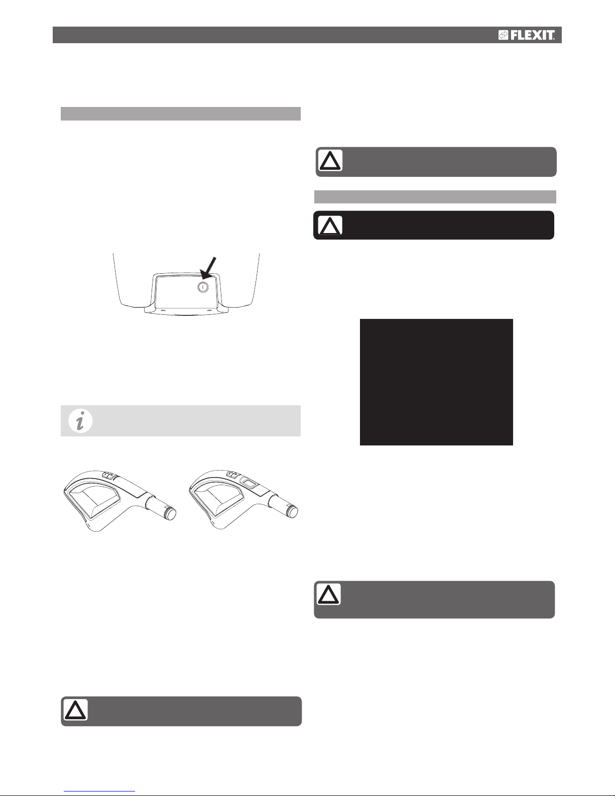
Start/stop button
All models have a start/stop button on the front to start and
stop the power unit, Fig. 7. The start/stop button can also be
used when/if you want to use a Flexit utility inlet to vacuum
direct from the machine (if you do not have a Flexit hose with
remote control) or for testing and demos.
Wireless communication LED/LCD
The machine is controlled wirelessly from the hose handle of
the vacuum cleaner. In this case you do not have to mount
a low voltage cable between the vacuum socket and the
machine.
On/off hose
Handle on hose with on/off button starting and stopping the
vacuum cleaner.
Manual hose
The vacuum cleaner starts and stops automatically when the
vacuum hose is connected to a vacuum socket. The metal
ring on the end of the hose closes the control circuit and the
vacuum cleaner starts up. When the hose is removed from
the vacuum socket, the vacuum cleaner stops.
Dustpan by the floor
Dustpan for mounting in a plinth under a cabinet will start and
stop the vacuum cleaner when opened and closed.
3.2 Servicing
If suction is poor, it indicates that the flow of air through the
machine is restricted. This may be due to the following:
•The dust bag is full and should be replaced.
•The filter is clogged and should be cleaned.
Thermal cutout
The vacuum cleaner has a thermal cut-out that trips if the
vacuum cleaner becomes overheated.
If this happens - unplug the main power cord to reset the
vacuum cleaner. Wait 5-10 minutes to allow the machine to
cool down. The vacuum cleaner should now start again. If the
cut-out trips again, you need to get a service firm to remedy
the fault.
Fig. 8
LED LCD
Always unplug the power cord before doing
any service work!
!
See description in section 9.
Requires a low voltage cable between the
vacuum socket and the machine
Fig. 9 Filter
3 Operating instructions CVR 1000
FFig. 7
While you are waiting, check the hose,
dust bag and filter to be sure that nothing is
blocking the flow of air through the machine
Requires a low voltage cable between the
dustpan and the vacuum cleaner

8
Never use the central vacuum cleaner
without a filter installed
!
4 Filter and dust bags - CVR 1000
Fig. 11
Fig. 12
Fig. 10
Filter
Filter
Motor housing
Fig. 13
Never vacuum without a dust bag installed
!
NB! Turn the edges of the dust bag down into
the container. This is to avoid damaging the
bag with the lid
4.2 Replacing / cleaning of filter
Open the lid and take out the dust bag as described earlier.
The filter sits at the bottom of the container around the
motor housing.
Pull the filter out of the container, Fig. 12. The filter can be
cleaned by shaking it or washing it in water.
If you wash the filter, you must let it dry completely before
refitting it.
Take the cleaned/new filter and place it in the bottom of the
container. Press the outer edge of the filter down against
the sides of the container so that the filter bulges up slightly.
Then push the filter down into place. Make sure the filter is
packed in tightly against the motor housing, Fig. 13. Reinstall
the dust bag and replace the lid. Check that the lid is firmly
secured.
4.1 Replacing the dust bag
The central vacuum cleaner is fitted with a dust bag as
standard.
Grasp the edge of the lid and pull upwards to open it, Fig. 10.
Replacing the dust bag: Remove the old dust bag by
turning the cardboard stiffener to the right or left so that the
raised part of the inlet is in line with the opening in the card.
Now slide the bag off the bag nozzle.
Fit the new dust bag as follows: Push the opening in the
cardboard over the elevation on the inlet and pull on the new
bag. Turn the cardboard to lock the bag in place.
The cardboard stiffener locks the bag in place when you
twist it as shown in Fig. 11.
The opening in the card must line up and slide over the
elevation on the inlet before you twist the cardboard
stiffener to lock it.
9
5 Assembly instructions CVR 2000 / CVR 3000 / CVR 4000
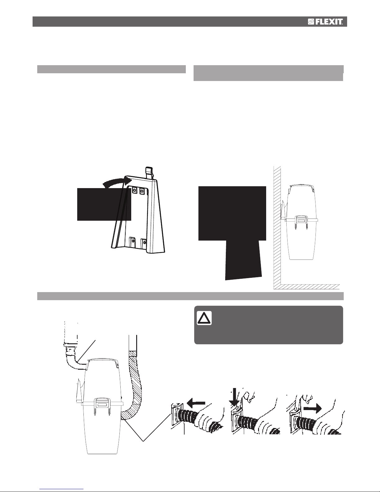
Fig. 14 Fig. 15
Outlet
Inlet
Fig. 16
5.2 Locating the vacuum cleaner on the wall
bracket
To facilitate the procedure, first remove the dust container.
Free the container by pulling both handles up and then
outwards. Then remove the container from the machine.
To
mount the vacuum cleaner/motor chassis to the wall bracket
- just lower the chassis downwards so that the locking device
of the bracket will pass through the slot of the chassis,
Fig. 15.
Make sure the corresponding bracket on the machine is held
firmly in place by the wall bracket.
When removing the vacuum cleaner from the wall bracket - push
the locking device towards you so it will release the bracket and
then lift the vacuum cleaner up from the bracket.
5.3 Connecting the machine
5.1 Fitting the wall bracket
Plan the positioning of the wall bracket so that there is
plenty of space above and below the area where the vacuum
unit is to be located. Make sure there is a minimum of 200
mm free space below the dust container.
Mark the positions for all four screw holes with a pen or
similar. The diameter of the holes in the holder is 5 mm.
Select screws and, if necessary, wall plugs suitable for the
type of wall concerned. Drill the four screw holes.
Fit the wall bracket with the large opening pointing
downwards, see Fig. 14. Then screw the holder firmly into
place.
The machine is connected with the flexible suction hose
in the lower position and the exhaust pipe uppermost, Fig
16. The flexible hose is connected to the dust inlet at the
container of the cleaner. Push the hose in to the inlet at the
cleaner until the hose locks.
Warning: If the pipe system in your house
has another diameter than a standard Flexit
pipe system, transition pieces can be bought
in a shop. Outer diameter of Flexit pipe
system is Ø51 mm
Push the hose in to the inlet at the cleaner until the hose locks.
Press the button on the hose inlet downwards in order to remove the
suction hose.
10
The attached rubber sleeve is used for tightening/loosening
the joint between the pipe system and the flexible vacuum
hose. Feed half the length of the sleeve into the vacuum
hose and fold the other half over. Then feed 5-10 mm of the
vacuum hose into the pipe system and fold the sleeve back
so that it envelopes the tail pipe.
The flexible suction hose acts as an adapter connecting the
vacuum unit with the pipe system.
NB! These connections must not be glued in
case the unit is handed in for service.
For additional information concerning the
assembly and installation of the pipe system and
low-current lead, please refer to the separate
assembly instructions supplied with the pipe
package.
Position the central vacuum cleaner so that the exhaust pipe
can be kept as short as possible, maximum. 5 metres. Take
the surroundings into consideration when positioning the
exhaust. For this reason, you should always fit a muffler.
6 Operating instructions - CVR 2000 / CVR 3000 / CVR 4000
6.1 Starting the machine
The central vacuum cleaner’s power cable must be
connected to a 230 volt mains socket. The appliance is
double-insulated and does not need to be earthed.
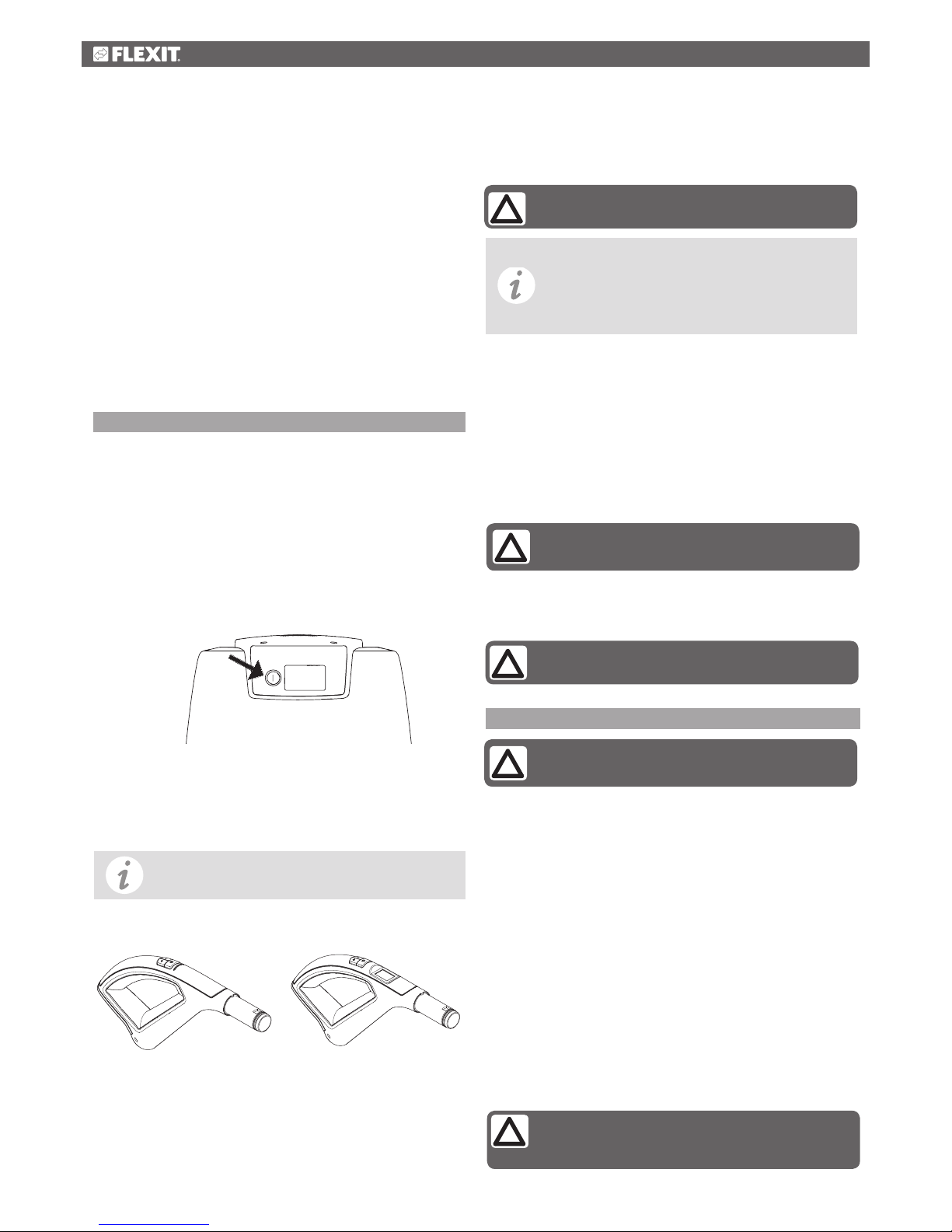
Start/stop button
All models have a start/stop button on the front to start and
stop the power unit, Fig. 17. The start/stop button can also be
used when/if you want to use a Flexit utility inlet to vacuum
direct from the machine (if you do not have a Flexit hose with
remote control) or for testing and demos.
Wireless communication LED/LCD
The machine is controlled wirelessly from the hose handle of
the vacuum cleaner. In this case you do not have to mount
a low voltage cable between the vacuum socket and the
machine.
On/off hose
Handle on hose with on/off button starting and stopping the
vacuum cleaner.
Fig. 18
LED LCD
See description in section 9.
Always unplug the power cable before doing
any service work!
Manual hose
The vacuum cleaner starts and stops automatically. When
the vacuum hose is connected to a vacuum socket, a metal
ring on the end of the hose closes the control circuit and the
vacuum cleaner starts up. Fig. 19. When the hose is removed
from the vacuum socket, the vacuum cleaner stops.
Dustpan by the floor
Dustpan for mounting in a plinth under a cabinet will start
and stop the vacuum cleaner when opened and closed.
While you are waiting, check the hose,
dust bag and filter to be sure that nothing is
blocking the flow of air through the machine
Fig. 17
Requires a low voltage cable between the
vacuum socket and the machine
Requires a low voltage cable between the
dustpan and the vacuum cleaner
6.2 Service
If suction is poor, it indicates that the flow of air through the
machine is restricted. This may be due to the following:
•The dust bag is full and should be replaced.
•The filter is clogged and should be cleaned of dust.
Thermal protector
The vacuum cleaner has a thermal cut-out that trips if the
vacuum cleaner becomes overheated.
If this happens - unplug the main power cord to reset the
vacuum cleaner. Wait 5-10 minutes to allow the machine
to cool down. . The vacuum cleaner should now start again.
If the cut-out trips again, you need to get a service firm to
remedy the fault.
On CVR 4000 which has a display, the symbol for overheating
will flash.

11
6.3 CVR 4000 Display
CVR 4000 has a display giving information about the
machine, Fig. 19.
Speed level
Shows at which of the five speed levels the machine is
operating.
Indicator for dust bag/bag filter
When the dust bag/filter symbol starts flashing
during operation, the cleaner tells you that it is
almost time to clean the bag filter and replace the dust bag/
empty the container. When it is time to do so, symbol will be
lit continuously. The dust bag/filter symbol will be lightened
after every 20 operation hours of the cleaner at the latest.
Reduced airflow indicator - lit
The reduced airflow symbol on the display indicates
that the airflow through the vacuum cleaner is
reduced. After 30 seconds of operation with reduced airflow,
the vacuum motor will be shot down in order to prevent
damage to the motor. If the reduced airflow symbol is lit and
the motor has been shot down, do like this: Check the bag
filter and dust bag (see Sections 7.1, 7.2, 7.3 and 7.4) to see
if anything is blocking the airflow. Also check that nothing is
blocking suction hose and/or vacuum sockets. Remove the
material causing the reduced airflow symbol to indicate.
Service indicator
When the service symbol starts flashing, the motor
will run for one more hour before it stops/will not
start. The purpose of the service symbol is to inform
you that it is time to order service of the cleaner. When
the symbol is continuously lit, the run time counter in the
cleaner has counted that the allowed amount of run time
has passed. You must now contact an authorised service
workshop and let them perform a service of the cleaner and to
reset the run time counter.
Overheat indicator - flashing
The overheat symbol indicates that the cleaner has
become overheated. The cleaner stops automatically.
Speed
Service
Dustbag/Filter
Wireless
Airflow
Temperature
Dust bag/bag filter
Overheating
Air flow
Signal
Fig. 19
Speed level
Unplug the main power cord to reset the vacuum cleaner and
wait 5-10 minutes to allow the machine to cool down. While
you are waiting, check the bag filter, container/dust bag,
suction hose and vacuum sockets to be sure that nothing is
blocking the flow of air through the machine.
Signal indicator - flashing
When the symbol is flashing, the hose handle is out of
range and there is no connection to the cleaner. The cleaner
will automatically stop after 30 min. if the hose handle or the
cleaner has not been activated.
Cleaning/replacement is described in
Section 7

12
7 Filter and dust bags - CVR 2000 / CVR 3000 / CVR 4000
of the cleaner till you hear a click. Push down the handles and
ensure that the vacuum unit and dust container are fitted
together properly.
7.3 Replacing the dust bag
The machine is supplied with a dust bag. Replace the dust
bag in the following way:
1. Release the two handles clamped on to the dust
container. The handles are easily unlocked by lifting up
the handles until they come to a stop. When you pull the
handles outwards away from the cleaner, the container is
released. Fig. 20.
2. Lift off the container.
3. Shake the dust from the bag filter. It may be
advantageous for the filter to be installed in the container
in such a way that dust in the filter can be shaken down
into the dust container.
4. Lift out the bag filter.
5. Remove the dust bag by taking hold of the cardboard
stiffener and carefully pulling out the card and bag from
the container, Fig. 22. Fold down the perforated part of
the cardboard towards the opening of the bag in order to
prevent the bag contents to leak out.
6. Empty the container of dust.
7.4 Fitting the dust bag
Replace the dust bag as follows:
1. Fit the dust bag’s card with a hole into the bag holder,
Fig. 23.
Fig. 21
Fig. 20
Fig. 23
Fig. 22
7.1 Replacing the filter
A bag filter must always be installed in the dust container.
Clean the filter in the following way:
1. Release the two handles clamping the dust container. The
handles are easily unlocked by lifting up the handles until
they come to a stop. When you pull the handles outwards
away from the cleaner, the container is released. Fig. 20.
2. Do not remove the filter from the container. Instead, give
the filter a light shaking inside the container to loosen dust
from the filter allowing it to fall into the container. This is
done by grasping the strap on the filter and quickly move
the filter up and down as shown in Fig. 21.
3. Lift out the bag filter. If a dust bag is being used - remove
the dust bag. Then empty the container of any remaining
dust in a suitable place.
7.2 Fitting the bag filter
Replace the bag filter in the machine as follows:
1. Replace the cleaned/shaken bag filter in the container.
Make sure the filter support fits into the inner edge of
the dust container properly. Check that the filter is fitted
the right way up - the cloth handle on the filter should be
visible.
2. Then replace the dust container with the bag filter in the
suction unit.
3. Attach the container on the suction unit by lifting the container
back in place and pushing the handles back in over the edge

13
2. Replace the cleaned/shaken bag filter in the container.
Make sure the filter support fits into the inner edge of the
dust container properly.
Check that the filter is fitted the right way up - the cloth
handle on the filter should be visible.
3. Replace the dust container on the vacuum unit. Close the
container on the vacuum unit by applying inward pressure
to the two handles to ensure the vacuum unit and dust
These products must though always be
operated with the bag filter fitted in the
cleaner
!
8 Electrical connecction
CVR 1000
The connection panel is
located in the bottom of
the vacuum unit
CVR 2000, CVR
3000, CVR 4000
The connection panel is
located in the top of the
vacuum unit
CVR 1000
Connection panel for low voltage lead
The low voltage leads are connected by snap lockings. Insert
leads in the snap lockings (one in each point). Secure the low
voltage cables by pulling the snap lockings at the connector
upwards.
Secure the low voltage
cables at the connector
Connect forcing
signal to this outlet.
Forcing signal ventilation unit
Connection to units capable of receiving pilot signal for
forcing of supply air.
When the vacuum cleaner starts, the ventilation unit
will increase the volume of air during vacuuming. This to
compensate for the air the vacuum cleaner draws out of
your house. When the vacuum cleaner is switched off, the
ventilation unit returns to original speed.
To be connected with a low voltage lead between the vacuum
cleaner and the ventilation unit.
Connection to ventilation unit; see
operating instructions of the unit
container are fitted together properly.
CVR 2000 / CVR 3000 / CVR 4000 can be run with or
without the installation of a dust bag - the choice is yours.
Connection of pilot current
The pilot current outlet (low voltage) is connected to a low
voltage lead running the length of the pipes. Both ends of
the low voltage lead are connected to the connection panel
on the vacuum unit. One lead to each outlet, see illustration
below.

14
9 Wireless communication - LED/LCD
9.1 Transmitter/receiver
Before you mount the transceiver box to the wall you should
always test if you have a signal between the transceiver box
and the hose handle in your entire home. Connect the box to
the cleaner and turn the cleaner on and off using the hose
handle from different places in your home.
Connecting the transmitter/receiver
To be able to use the wireless Flexit hose
handles, you must first connect the
transmitter/receiver to the cleaner. This is
done by using the 2 meter network cable
(RJ45) that comes with the transmitter/
receiver. Connect the cable to the
transmitter/receiver and the right socket in
the back of the cleaner.
Installing the transmitter/receiver
Mount the transmitter/receiver on the wall minimum 1
meter (if possible) away from the cleaner for best signal
between the transmitter/receiver and the hose handle. The
transmitter/receiver can be moved to different places in
your home for a better range by using an up to 30 meter
network cable. Cables can often be bought in your local
Electronics store.
The first transmission
The hose handle and the cleaner needs to have a first
communication before starting the cleaner. This is also valid
if the hose handle has been replaced (spare part) or if you
want to connect an extra hose. Do like this before starting
your wireless cleaner:
1. Unplug the main cord.
2. Plug in the cord again, and then push the on/off button at
the hose handle for approximately 10 seconds. This must
be done within 60 seconds after the cleaner has been
plugged in
3. The handle and the cleaner do now communicate.
9.2 Wireless hose handle
Instructions for use
The on-off function and power regulation is controlled by
radio technology.
Start and stop
Start: One push at the switch will start the cleaner.
Stop:One push at the switch will stop the cleaner.
The power regulation can be adjusted in 5 steps. You switch
between the different steps by pressing the (+) or (-) buttons
at the hose handle.
LED
The LED-indicator is placed above the on/off button and will
be activated with different lights depending on the actions
that are taken: The lamp is activated at start or stop actions
or when the power regulation is adjusted.
The lamp flashes a warning light that indicates that the bag
filter is clogged or that the container/dust bag is full and
needs cleaning/replacement (see Section 7).
LCD info center display
The display is placed above the on/off button and will show
different symbols depending of the status of the cleaner.
Speed level: Bars shows the actual speed level.
Low Battery: The batteries are below 5 %. Replace
batteries. See Battery, this section.
Signal: Signal flashes if the hose handle is out of
reach. No contact to the vacuum cleaner.
Bag/filter: The container symbol flashes or glows
regularly. Check bag filter and dust bag. See section
6.3, Indicator for dust bag / bag filter.
Air flow blocked: When the service and
the container symbol glows simultaneously,
it indicates that the air flow through the
vacuum cleaner is reduced. Se section 6.3, Reduced airflow
indicator.
Service warning: Warning that it is almost time to
order service or that the allowed working time has
been reached. See section 6.3 Service indicator.
Overheating: Flashing symbol indicates that the
vacuum cleaner is overheated. The vacuum cleaner will
stop automatically. See section 6.3 Overheat indicator.
Overheating
Signal
Bag/filter
Speed level
Low battery
Service
Start/stop
Power regulation +
Power regulation -
LED-
indicator
+
15
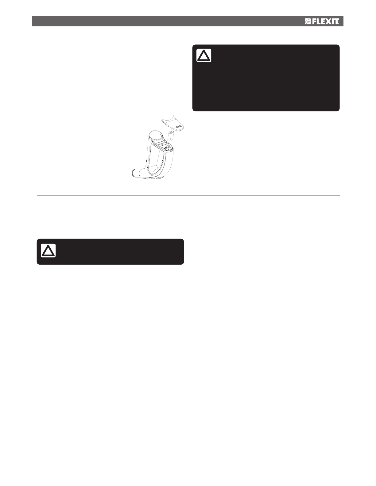
Battery
The lifetime of the enclosed batteries in the bent end is
approximately three (3) years. If the battery capacity is to
low, the cleaner will then be shut off. If the cleaner would not
start or the power regulation via the hose handle does not
work, you must replace the batteries at the hose handle.
Replace to battery type 1.5V AAA. For more information and
trouble shooting see Section 10 in this instruction for use.
How to replace the batteries in the hose handle
1. Open the lid of the battery holder by sliding
the lid towards the front of the hose handle.
2. Replace the used batteries with two
new ones, type 1.5V AAA. Make sure
the polarity of the batteries is placed
correct at the bracket.
3. Slide the battery lid back until you
hear a click.
10 Troubleshooting
The vacuum cleaner will not start
Thermal protector
The vacuum cleaner has a thermal cut-out that trips if the
vacuum cleaner becomes overheated.
If this happens - unplug the main power cord to reset the
vacuum cleaner. Wait 5-10 minutes to allow the machine
to cool down. While you are waiting, check the bag filter,
container/dust bag, suction hose and vacuum socket to
be sure that nothing is blocking the flow of air through the
machine. The vacuum cleaner should now start again. If the
cut-out trips again, you need to get a service firm to remedy
the fault.
On CVR 4000 the symbol for overheating will show in the
display of the vacuum cleaner.
Other troubleshootings
•Are you using the correct hose? Only the original hoses
fit correctly.
•Does the vacuum cleaner start when you try a different
vacuum socket? If so, there is a fault in the electrical
connection to the first socket. Unscrew the socket and
check the connection at the back.
•Is the power supply connected to the vacuum unit?
•Is there power at the socket?
•Is the low-voltage lead connected to the vacuum unit?
•The batteries to the wireless hose handle may have been
discharged. Replace the batteries with new ones, type 1.5V
AAA.
The vacuum cleaner will not stop
•Has a metal object become lodged in one of the vacuum
sockets causing the pins to become fused?
Poor suction power
•Are all the vacuum sockets closed properly?
•Has something become jammed in one of the vacuum
sockets?
•Is the container lid closed properly?
•Is the gasket between the container and the lid in place?
•Is it damaged?
•Is the pipe system blocked?
•Is the dust bag full or clogged?
•Is filter clogged?
CVR 4000 Display
The CVR 4000 model has a display giving information about
the machine, Fig. 19.
All work involving the 240 volt mains
electricity supply must be carried out by a
qualified electrical contractor
!
WARNING!
Do not pull out the suction hose from the
cleaner while the cleaner is still running as
it will cause too little airflow through the
cleaner.
The machine has a safety shut off function
and a thermal protector which will stop the
machine but this will cause an unnecessary
abrasion on the motor
!

16
10.2 Service/maintenance - CVR 2000 / CVR 3000 / CVR 4000
Dust
container
Should be emptied
before the container is
3/4 full, depending on
use but normally 2-4
times a year.
Poor suction and
danger of creating
a blockage in the
pipe system.
Release the two handles clamping the dust container. The handles
are easily unlocked by lifting up the handles until they come to a
stop. When you pull the handles outwards away from the cleaner,
the container is released. Lift off the container. Lift out dust bag
and. Empty the container in a plastic bag and put in dustbin. Any
remaining dust or fluff can be removed manually.
Dust bag Should be replaced
before it becomes
completely full,
depending on use but
normally 2-4 times a
year.
Poor suction and
danger of creating
a blockage in the
pipe system.
Release the two handles clamping the dust container. The handles
are easily unlocked by lifting up the handles until they come to a
stop. When you pull the handles outwards away from the cleaner,
the container is released. Lift off the container. Lift out the filter.
Then remove the dust bag by pulling the bag’s cardboard stiffener
off the nozzle. Replace in reverse order.
Should be shaken when
the container is emptied.
NB: Only use dry
cleaning methods
To maintain good
suction power.
Filter Release the two handles clamping the dust container. The handles
are easily unlocked by lifting up the handles until they come to a
stop. When you pull the handles outwards away from the cleaner,
the container is released. Lift off the container. Do not remove the
filter from the container. Instead, give the filter a light shaking inside
the container to loosen dust from the filter and allow it to fall into
the container. Lift out the bag filter. If a dust bag is being used -
remove it. Then empty the dust from the container in a plastic bag
and put in dustbin.
Should be replaced
before it becomes
completely full,
depending on use but
normally 2-4 times a
year.
Poor suction and
danger of creating a
blockage in the pipe
system.
Dust bag Grasp the edge of the lid and open it by pulling upwards. Remove
the old dust bag by turning the cardboard stiffener to the right or
left so that the elevation on the nozzle penetrates the opening in
the cardboard. Now slide the bag off the inlet. Push the opening in
the cardboard over the elevation on the inlet and pull on the new
bag. Twist the cardboard to lock the bag in place. NB! The opening
in the card must be adjusted and pushed past the elevation on the
inlet before the cardboard can be locked into place with a twisting
action. Note: Never vacuum without a dust bag installed.
Filter in
bottom
Should be checked when
changing the bag.
Poor suction can
result. Dust can find
its way into
the motor.
10.1 Service/maintenance - CVR 1000
Remove the dust bag as described above. Remove the filter from
the bottom. The filter can be cleaned by shaking it or washing it in
water. NB! The filter must be completely dry before being reinstalled.
Replace the cleaned filter in the machine. Press the outer edge of
the filter down against the sides of the container so that the filter
bulges up slightly. Refit the dust bag and replace the lid. Check that
the lid is sitting firmly in place. Note: Never vacuum without a filter
installed.
Product How often? Why? How?
Product How often? Why? How?
NB! Never vacuum without a filter and a dust
bag installed
!
NB! Never vacuum without a bag filter
installed
!

17
11 Dimensional drawings CVR 1000, CVR 2000, CVR 3000, CVR 4000
Målskisser i mm.
CVR 2000 / CVR 3000 / CVR 4000
CVR 1000
66
395
219115392
799
Min 200 Min 400
68
44
360
33
115
222
427
38
44
Attach to wall

18
12 Symbol explanation
Indicates for
service warning,
See 10
Trouble-
shooting
Signal lit
Signal flashing
Explanation of the indication lights at the LCD handle
Indicates for
blocked airflow,
See 10
Trouble-
shooting
Dust bag or
filter is clogged.
Change dust
bag and clean
filter.
Bag/filter
Air flow
Service
Bars show
the actual
speed level
Speed level
Hose handle is
out of range. No
connection to
the cleaner.
Thermal cut-out
has tripped and
the cleaner has
stopped. See 10
Troubleshooting
Signal Overheating
Explanation of indication lights at the display for CVR 4000
Bars show
the actual
speed level
Battery is
under 5%.
Change
battery
Indicates for
service warning,
See 10
Trouble-
shooting
Signal lit
Signal flashing Dust bag or
filter is clogged.
Change dust
bag and clean
filter.
Bag/filter
Service
BatterySpeed level
Hose handle is
out of range. No
connection to
the cleaner.
Thermal cut-out
has tripped and
the cleaner has
stopped. See 10
Troubleshooting
Signal Overheating

19

Flexit AS, Televeien 15, N-1870 Ørje www.flexit.com
Table of contents
Other Flexit Vacuum Cleaner manuals


