FlexRadio FLEX-6400 User manual

Page 1 © 2018 FlexRadio Systems, V1.2
FLEX-6400(M) and 6600(M) GPSDO
Installation Guide
February 1, 2018
Thank you for purchasing the FLEX-6000 GPSDO Kit. The following guide will provide the necessary step-
by-step procedure for installing the FLEX-6000 GPSDO module in a FLEX-6400, FLEX-6400M, FLEX-6600 or
FLEX-6600M software defined radio.
Obtaining Technical Support
If you encounter any issues installing or operating SmartSDR for Windows with FlexRadio Systems’
Signature Series software defined radios, please use our online Community
(https://community.flexradio.com/) to query for information about SmartSDR for Windows and the FLEX-
6000. If you need assistance using the Community, please refer to the community topic “How to use the
FlexRadio Systems Support Community”.
If you are unable to find an existing answer to your issue in the Community, please contact FlexRadio
Systems technical support by opening a HelpDesk support ticket online at https://helpdesk.flexradio.com/
For details on how to submit a HelpDesk support ticket, please refer to the following URL:
https://helpdesk.flexradio.com/hc/en-us/articles/202118688-How-to-Submit-a-Request-for-Technical-
Support.
Hours of Operation: Our Technical Support engineers are available Monday-Friday from 9:00am-5:30 pm
Central Time. If you open a HelpDesk ticket after business hours, on a holiday or weekend, we will
respond to your request for assistance during regular business hours in the order your HelpDesk ticket
was received.
Page 2 © 2018 FlexRadio Systems, V1.2
Getting Started
Required Tools
•A non-metal prying device
•A 5/32” (4mm) nut driver or socket wrench
•A 5/16” (8mm) open-ended wrench, nut driver or socket wrench
•T8 TORX driver
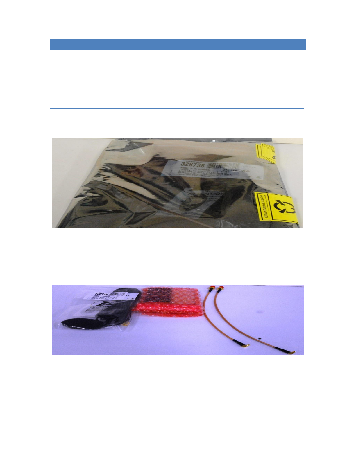
Packaging and GPSDO Kit Contents
Your FLEX-6000 GPSDO will arrive in an anti-static package similar to the one shown below.
Remove the contents and verify that the following items are included before proceeding. Refer to the
image below.
•One (1) GPS patch antenna
•One (1) GPSDO assembly
•Two (2) coax assembly cables (one cable may be shorter)
•Two (2) threaded 5/32” (4mm) spacers

Page 3 © 2018 FlexRadio Systems, V1.2
Preparing to Install the GPSDO Module
The back panel plugs and top cover must be removed before the GPSDO can be installed.
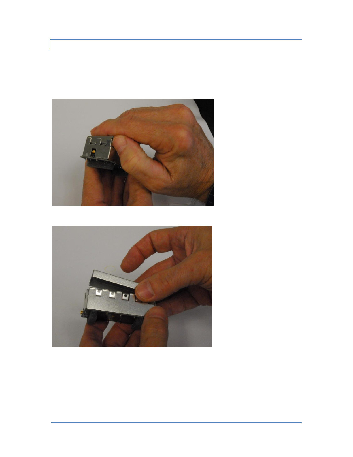
Removing the Back-Panel Metal Plugs
Place the FLEX-6000 on its feet with the back facing you as shown in the image below.
Using your fingernail or another non-metal prying device, remove the two (2) metal plugs from the back
panel below the labels:
•GPS ANT
•10 MHz OUT

Page 4 © 2018 FlexRadio Systems, V1.2
Removing the Top Cover
The top chassis cover for the FLEX-6000 must be removed before the GPSDO can be installed.
Using the T8 TORX driver remove the four (4) short Top Cover screws on the FLEX-6000.
Then remove the remaining five (5) short Side Cover Side screws from each of the right and left sides of
the FLEX6000. Retain the screws for re-installation. The images below show the Side Cover screws.
Once the top cover retaining screws have been removed, gently pull the Top Cover upwards to remove it
from the FLEX-6000.

Page 5 © 2018 FlexRadio Systems, V1.2
Installing the GPSDO Assembly in the FLEX-6000
Once the top cover and chassis plugs have been removed, the GPSDO module can be installed into the
FLEX-6000.
Installing the Internal Coax Cabling
Locate the long coax cable assembly (if there is a longer one in the kit) and remove the SMA connector
cap, hex nut, and lock washer.
Slightly bend the coax at the SMA connector end of the assembly to facilitate inserting the threaded end
of the coax cable assembly through the back-chassis hole labeled 10MHZ OUT. This is the hole located in
the far right-hand corner of the back-panel chassis.
While firmly holding the long cable assembly in place with one hand, install the lock washer on the
threaded SMA connector. Carefully install the SMA connector 5/16” (8 mm) hex nut on the threaded SMA
connector being careful not to cross-thread the SMA connector. Tighten the hex nut with your fingers so
that the coax cable assembly will freely rotate.
Insert the threaded end of the short coax cable assembly (if there is a shorter one in the kit) through the
back-chassis hole labeled GPS ANT at the center-right of the back-panel chassis.
While firmly holding the short cable assembly in place with one hand, install the lock washer on the
threaded SMA connector. Carefully install the SMA connector 5/16” (8 mm) hex nut on the threaded SMA
connector being careful not to cross-thread the SMA connector. Tighten the hex nut with your fingers so
that the coax cable assembly will freely rotate.
Page 6 © 2018 FlexRadio Systems, V1.2
Installing the GPSDO Module Assembly
The next step is to install the GPSDO module assembly into the FLEX-6000.
If installed, remove the GPSDO RF shield from the module housing by gently prying it upwards on all four
sides evenly as shown below. Be careful not to bend the retaining teeth by prying up one side more than
another.
Gently lift off the shield as shown below.
Page 7 © 2018 FlexRadio Systems, V1.2
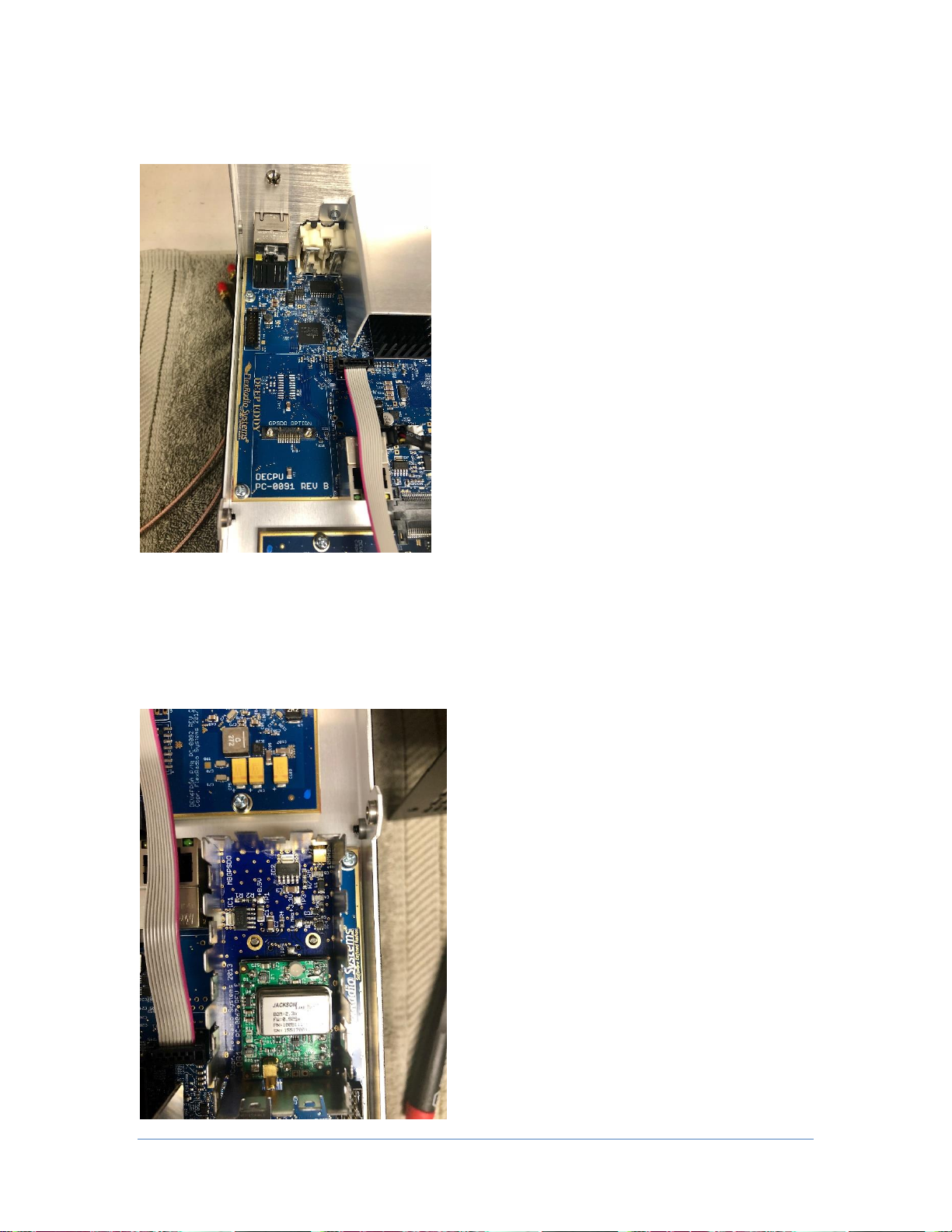
In the left rear of the FLEX-6000 TRX circuit board, locate the area where the GPSDO module will be
installed. It is clearly marked adjacent to a ribbon cable and Ethernet jack.
Orient the GPSDO module assembly so that the TCXO (large rectangular silver component on the PC
board) is facing the rear of the FLEX-6000.
Insert the GPSDO module assembly onto the printed circuit board so that the two (2) threaded screw
studs are visible inside the GPSDO assembly as shown below. When oriented correctly, press down firmly
to properly seat the GPSDO assembly module.
Page 8 © 2018 FlexRadio Systems, V1.2
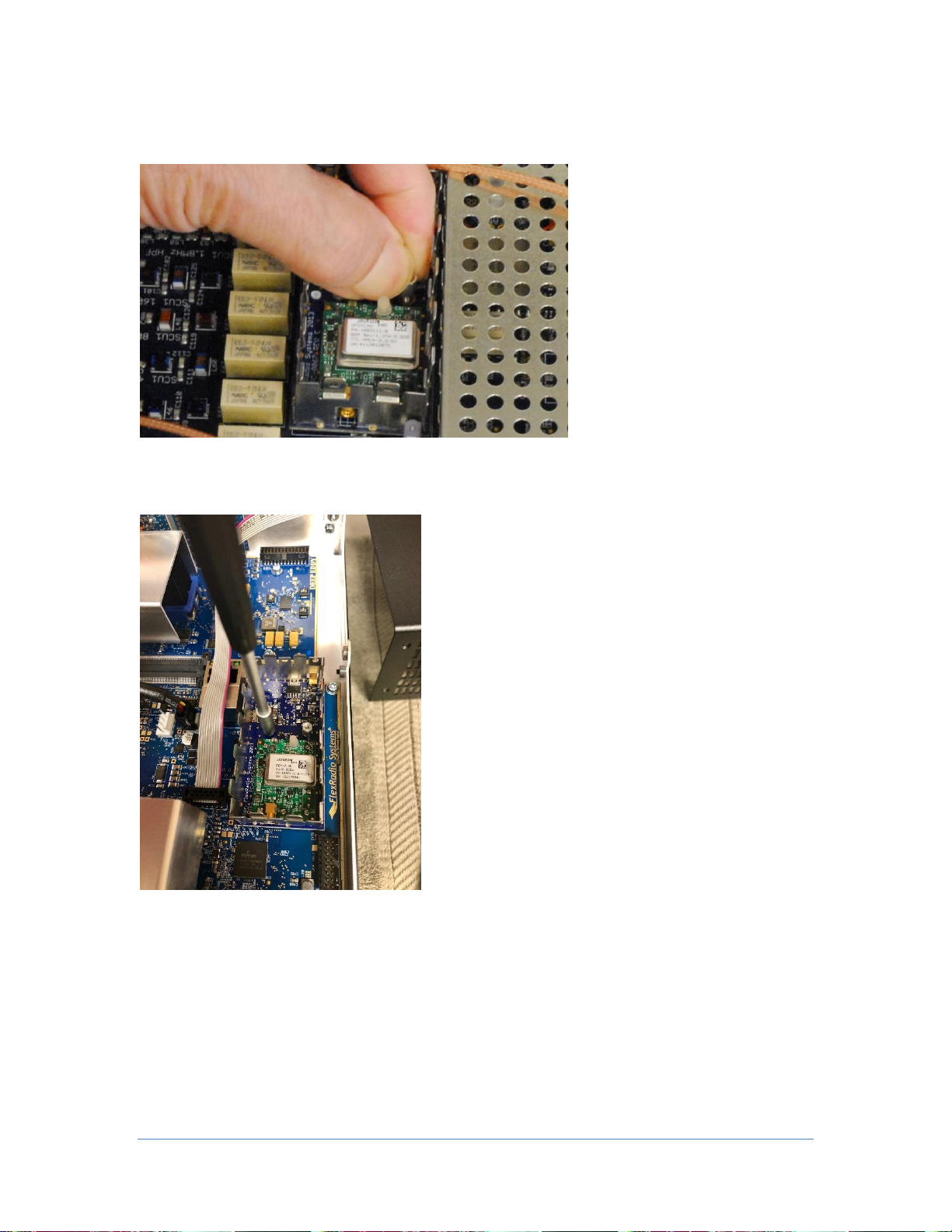
Carefully thread a 5/32” (4mm) spacer onto each threaded stud as shown in the image below, making
sure not to cross-thread the stud.
Using a 5/32” (4mm) socket wrench or nut driver gently tighten the spacers on the threaded stud to firmly
attach the GPSDO assembly module to the printed circuit board. Do not over tighten the threaded spacer.
Page 9 © 2018 FlexRadio Systems, V1.2
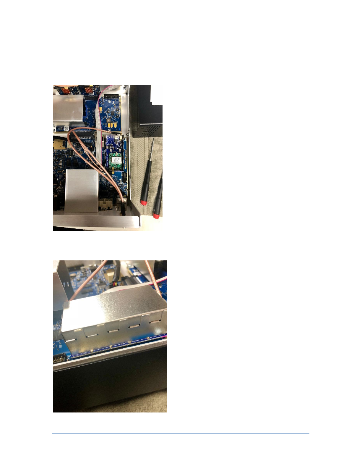
Press the 10MHZ OUT coax assembly onto the MMCX connector on the GPSDO assembly module closest
to the front of the FLEX-6000 as shown below.
Press the GPS ANT coax assembly onto the MMCX connector on the GPSDO assembly closest to the back
of the FLEX-6000 as shown below.
Replace the RF shield on the top of the GPSDO assembly module making sure that it is pressed down
firmly, as shown below, to prevent EMI leakage.

Page 10 © 2018 FlexRadio Systems, V1.2
Orient the coax assemblies, as shown above, lying as flat as possible. While holding the coax assembly in
one hand, use either a 5/16” (4mm) open-ended wrench, socket or nut driver as shown below to slightly
tighten the SMA connector hex nut to prevent the SMA connector from rotating.
Tighten the SMA retaining nut on both coax assemblies.
Be careful not to scratch the back panel of the FLEX-6000 when tightening the SMA connector hex nuts.
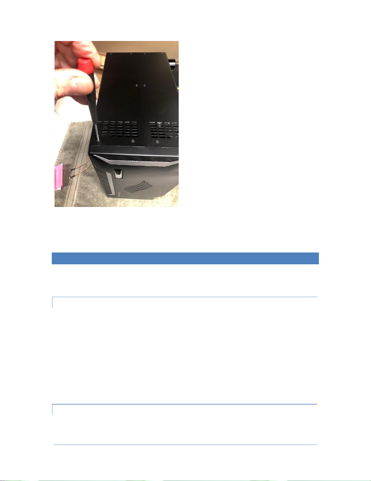
Reinstalling the Top Cover
Replace the top chassis cover on the FLEX-6000. Orient the cover so that the row of vent holes on the top
cover is facing towards the front of the FLEX-6000 as shown below.
Page 11 © 2018 FlexRadio Systems, V1.2
After reinstalling the top cover install the four (4) black TOP Cover screws, and the five (5) side cover
screws on each side, using the T8 TORX driver.
Preparing the GPSDO for First Use
Before using the GPSDO for the first time, the FLEX-6000 must be put back into its operating position and
the GPS patch antenna installed.
Location Considerations for the GPS antenna
The supplied GPS patch antenna needs to be installed indoors on a window that has a good view of the
horizon to receive the GPS signals from the geostationary satellites. A south facing window is ideal for the
reception of the greatest number of GPS satellites. This is required to discipline the TCXO.
If the FLEX-6000’s operating position does not facilitate installing the GPS antenna using the low-loss
coaxial cable as described above, an external weatherproof GPS antenna will be required for proper
operation. RG-59 coax is a good choice and easily obtainable for cable lengths under 150’ and LMR400 for
runs exceeding 150’.
Installing the GPS Patch Antenna
Being careful not to cross-thread the SMA connector, screw the patch antenna SMA plug into the gold
SMA connector labeled GPS ANT.

Page 12 © 2018 FlexRadio Systems, V1.2
Using the double-sided adhesive oval that is included with the patch antenna, mount the GPS patch
antenna on a window with a good view of the horizon. The side of the patch antenna without any text
(example: Pulse) should be the side facing the horizon.
Enabling the GPSDO Module on FLEX-6400 and FLEX-6600
Power on the FLEX-6000 and allow it to completely boot up.
Start SmartSDR for Windows and connect to the FLEX-6000.
From the SmartSDR for Windows Menu Bar, open the Settings menu option. Then select the Radio Setup
Menu.
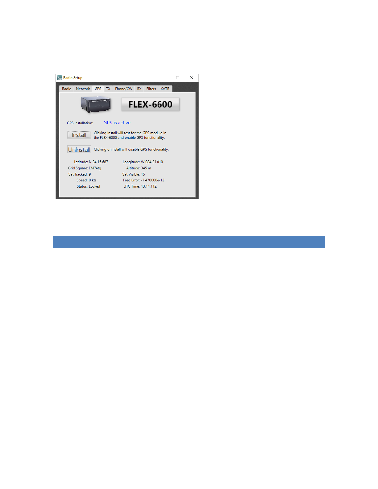
Select the GPS tab. Click on the Install button as shown below.
Enabling the GPSDO Module on FLEX-6400M and FLEX-6600M
Power on the FLEX-6400M or FLEX-6600M and allow it to completely boot up.
Tap the MENU button in the top center of the display to open the Main Menu. Tap the GPS tab to open
the GPS sub-menu. Tap on the Install button, then close the menu.
Verifying the Operation of the GPSDO Module
Once the GPSDO module and been installed (enabled), it will take several minutes for it to acquire the
GPS satellites, enable a lock and begin disciplining the TCXO. It may take up to 24 hours for maximum
frequency stability as GPSDOs are a long-term discipline method for crystal oscillators.
When the GPSDO has been properly installed, the following indicators are shown.
The Power button status LED will change from Green to either solid Yellow or flashing or solid Blue
depending on the lock state of the GPSDO module.
•Yellow: GPSDO is initializing
•Flashing Blue: GPSDO is initialized, but has not achieved a satellite lock
•Solid Blue: GPSDO is initialized and locked
Page 13 © 2018 FlexRadio Systems, V1.2
When the GPSDO has initialized, the GPS installation state will be indicated as “active” and GPS status
data will be displayed in the Radio Setup -> GPS tab as shown below, or on the Main Menu GPS tab on the
FLEX-6400M and FLEX-6600M.
Copyrights and Trademarks
© 2005-2018 FlexRadio Systems. All rights reserved.
FlexRadio Systems is a registered trademark of Bronze Bear Communications, Inc. DBA FlexRadio Systems.
FLEX-6300, FLEX-6400, FLEX-6400M, FLEX-6600, FLEX-6600M, FLEX-6500, FLEX-6700, FLEX-6700R,
Maestro, FlexControl, PowerGenius XL, SmartSDR, SmartSDR for Windows, SmartSDR for iOS, SmartSDR
CAT, SmartLink, DAX, TNF, WNB, the SmartSDR “spectrum” (logo) and the FlexRadio Systems "wave"
(logo) are trademarks of FlexRadio Systems.
FlexRadio Systems
4616 W. Howard Lane
Suite 1-150
Austin, TX USA 78728
+1 (512) 535-4713
www.flexradio.com
Other manuals for FLEX-6400
3
This manual suits for next models
3
Table of contents
Other FlexRadio Transceiver manuals


