impact PowerSync 16-80 User manual

1
PS-80
PowerSync 16-80
Transceiver
INSTRUCTIONS
2.4 GHz 80-Channel
Transceiver
2.4GHz

2
Introduction ...........................................................................................................3
Key Features .......................................................................................................4-5
Contents ................................................................................................................5
Device Layout / LCD............................................................................................6-7
Precautions ............................................................................................................8
Installing the Batteries ...........................................................................................9
Mode Selection....................................................................................................10
Channel Selection ................................................................................................11
Groups ............................................................................................................12-13
Compatible Devices / Backwards Compatibility..............................................14-15
Using the Transceiver with Your Flash.............................................................16-19
Using Your Transceiver as a Shutter Release .................................................20-28
Advanced Features ........................................................................................29-33
Troubleshooting ...................................................................................................34
Specifications .....................................................................................................35
FCC Compliance ..................................................................................................35
Warranty ............................................................................................................36
Table of Contents

3
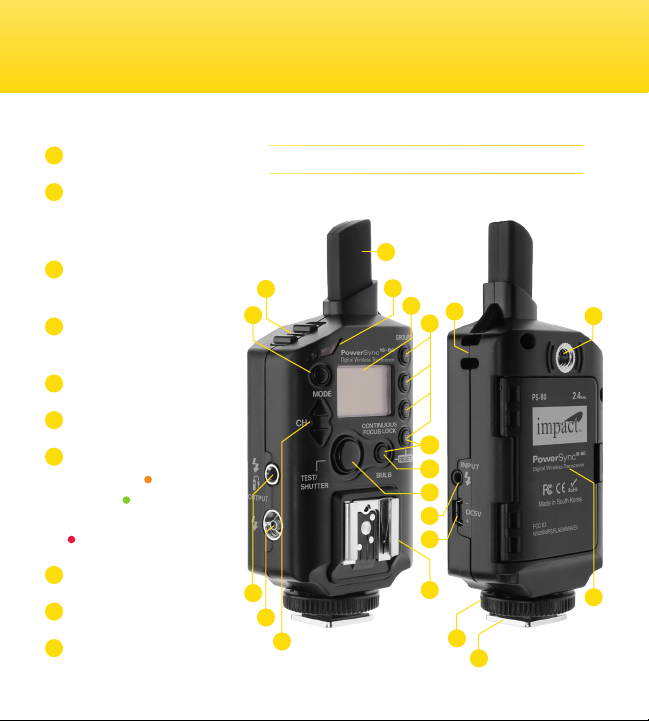
Congratulations on the purchase of your Impact PowerSync 16-80 Transceiver.
This multi-purpose 2.4 GHz 80-channel digital wireless transceiver empowers
users to remotely trigger flash and camera devices. With the use of a minimum
of two PowerSync 16-80 units, you can enjoy the freedom of triggering from a
distance up to 720 feet (220 m).
The PowerSync 16-80 was designed to give photographers an easy to use,
high-quality radio slave system. The wireless control capability eliminates the
presence of cable clutter, making it ideal for studio or outdoor flash scenarios.
Remote triggering is a secondary ability of the PowerSync 16-80. This is helpful
when a subject, such as wildlife, may be difficult to approach. Additionally, the
wireless function of the device removes the potential of camera shake, making it
ideal for macro, close-up, and long exposure photography.
The PowerSync 16-80’s grouping and range-extending functions create easy to
control transitioning between pre-set devices for off-camera and long-distance
triggering. The adaptive PowerSync 16-80 is also backwards compatible with
the PowerSync 16, enabling owners to use the PowerSync 16-80 with their older
units. One PowerSync unit is able to wirelessly trigger many compatible units.
Its small size and included pouch make the PowerSync 16-80 simple to store and
transport.
To fully understand and best use the functions and capabilities of your PowerSync
16-80, please take a moment to read through this user guide.
Introduction

4
Key Features:
•DigitalWirelessTransceiver: Powerful multipurpose transmitter/receiver
that can act as a flash trigger and remote shutter release for multiple devices
simultaneously.
•SyncSpeed: Offers a maximum sync speed of 1/250 second, allowing the user
to capture images wirelessly in most shooting scenarios.
•80DigitalChannels: Perfect for operating multiple devices wirelessly without
having to worry about radio or flash interference.
•DigitallyCoded2.4GHzSignal:A stronger and more reliable radio signal that
allows the units to communicate, even with barriers between them, eliminating
the need for a line-of-sight between devices.
•BackwardCompatibility: Compatible with the Impact PowerSync 16
transmitter and receiver units.
•FourIndividualGroupings: Provides the user with the ability to wirelessly
bundle multiple units in bunches, creating separate groups with alternate
settings.
•IdealforLong-ExposureandMacroPhotography:The hands-free shutter
release features of the device make it perfect for photography situations where
eliminating camera shake is an asset.

5
•ExtendedWirelessRange: Has the ability to extend the device’s signal range
with the use of multiple units for flash and camera triggering.
•Auto-Syncing: This synchronizes your remote flashes with a camera’s shutter
release using only three transceiver units.
Contents Include
1Transceiver
2Lanyard
3Pouch
43.5 mm to 3.5 mm flash sync cable
53.5 mm to 1/4” cable adapter
62.5 mm to PC flash sync cable
72x AA alkaline batteries
8Self adhesive, adjustable
accessory shoe
9User guide
1
2 3
4
7
6
8
5
9
1
PS-80
PowerSync 16-80
Transceiver
INSTRUCTIONS
2.4 GHz 80- Channel
Transceiver
2.4GHz

6
Overview
Device Layout
1Power switch
2Mode (Transmitter
TX, Receiver RX, or
Transceiver TX/RX)
33.5 mm output for flash/
shutter release cable
4Female screw-in PC
port output
5Channel selector
6Integrated antenna
7LED status light
Auto focus: orange
Shutter: green
Power on confirmation:
blinking red
8Backlit LCD screen
9Group selector
10 Lanyard loop connection
17
6
10
12
11
13
14
16
15
4
5
9
17
19
18
20
3
28

7
LCD
B
FL
A
TxRx
ON LY
B
C
D
LOW
11 Reset (Press “Bulb”
and Group “D” button
for 3 seconds)
12 Bulb mode/Continuous
focus lock
13 Test (flash)/Shutter
Release Button
(shutter)
14 2.5mm PC input
15 mini-USB Type B/DC5v
adapter port
16 Receiver hot shoe
mount
17 Locking thumbwheel
18 Transmitter shoe foot
19 Battery compartment
20 ¼-20” female threaded
socket
28
22
23
21 Tx/Rx mode indicator
22 Channel indicator
23 Shutter indicator
24 Focus confirmation
25 Signal verification
26 Bulb mode indicator
27 Continuous focus
lock indicator
28 Group indicator
29 Battery status
2921
27262524

8
Precautions
• There are no user-serviceable parts inside the devices. Do not attempt to disassemble
or perform any unauthorized modification.
• Do not operate the PowerSync 16-80 in the presence of flammable gas or vapors.
• Do not handle with wet hands or immerse in or expose to water or rain. Failure to
observe this precaution could result in fire or electric shock.
• Keep out of the reach of children. This device contains small parts which may pose a
choking hazard.
• Observe caution when handling batteries. Batteries may leak or explode if improperly
handled. Use only the batteries listed in this manual. Make certain to align batteries
with the correct polarity.
• Batteries are prone to leakage when fully discharged. To avoid damage to the product,
be sure to remove the batteries before leaving the product unattended for prolonged
periods or when no charge remains.
• Do not use or leave the devices in conditions of extreme heat, severe cold, or high
humidity.
• Turn off the camera and/or flash’s power before inserting or removing any cord.
• Dispose of used batteries, packaging, and old devices in accordance with appropriate
local environmental regulations.
• All images are for illustrative purposes only.

9
Installing the Batteries
The battery compartment is located on the rear of the device. To install the
batteries, open the compartment door and carefully slide two AA batteries into
position. Ensure that the polarity of the batteries match the icons shown within
the compartment.
The PowerSync 16-80 may also be powered using a mini-USB type B DC5v AC
adapter.

10
Mode Selection
Transmitter(Tx:)
Transmitter mode sets the transceiver to only send out signals to other devices.
No incoming signals will affect the device while this mode is initiated.
Receiver(Rx):
Receiver mode sets the transceiver to only accept incoming signals from
transmitting devices. This mode does not allow the device to send out signals.
Transmitter/Receiver(Tx/Rx):
Transmitter/Receiver mode allows the transceiver to both send and receive
signals to or from other devices simultaneously.
To change the mode on your PowerSync 16-80, press and hold the M button until
the current mode begins to blink on the LCD screen. Press the M button again
until your desired mode is displayed on the LCD screen.
NOTE: Using Tx/Rx mode increases the chance of signal interruptions between
communicating devices in the presence of many PowerSync 16-80 units. For the
most reliable signal transmission or reception, use either Tx or Rx mode when
possible.

11
Channel Selection
The Impact PowerSync 16-80 provides the user with 80 individual channels. To
set a device’s channel, push and hold the Channel Selector buttons, up or down,
for two seconds until the channel number begins to blink. Press the Channel
Selector buttons up or down to select the desired channel number.

12
Compatible Devices
The PowerSync 16-80 does not transmit TTL (through-the-lens) settings. A flash,
with full manual output control is required for use with this device. Most manual
flashes are compatible with the PowerSync 16-80’s receiver hot-shoe mount.
Ones that are not are the Sony/Minolta, Sony Multi-Interface, and Pentax flashes.
The hot-shoe foot is compatible with all hot-shoe cameras except for Sony/
Minolta and Pentax.
Backwards Compatibility
The PowerSync 16-80 is backward compatible with the PowerSync 16 Radio
Slave System.
PowerSync16TransmittertoPowerSync16-80asReceiver:
The PowerSync 16 transmitter can be used to trigger the PowerSync 16-80. Set
your PowerSync 16-80 to Receiver (Rx) or Transmitter/Receiver (Tx/Rx) mode
using the M button to accept a signal from the PowerSync 16 transmitter. Ensure
the channel on both devices is identical. See chart below.
PowerSync16-80TransmittertoPowerSync16asReceiver:
The PowerSync 16-80 can be used to trigger the PowerSync 16 receiver. Set your
PowerSync 16-80 to Transmitter (Tx) or Transmitter/Receiver (Tx/Rx) mode using

13
the M button to send a signal. Ensure the channel on both devices is identical.
See chart below.
For channel selection, the PowerSync 16 system relies on manual channel
selector switches. Despite the PowerSync 16-80’s digital interface, channels on
the two devices can be synchronized using the chart below as a guide:
Note: When using the PowerSync 16 – only 16 channels are available.
The PowerSync 16-80’s backward compatibility with the PowerSync 16 system
will only work if No Group is selected on the PowerSync 16-80.

14
A transceiver is a device comprising both a transmitter and a receiver combined to share
common circuitry or a single housing.
MountingtheTransceiver(Transmitter):
Connecting the Transceiver to Your Flash
Using the Transceiver with Your Flash
OnaCamera: With all of the devices
turned off, slide the transceiver onto your
camera’s hot-shoe mount. Tighten the
locking ring to secure.
OnaBracket: With all of the devices
turned off, slide the transceiver onto the
bracket’s cold shoe-mount. Connect the
devices with the included 2.5 mm to PC
cable, with the 2.5 mm end inserted in the
transceiver’s input. Then plug the PC end of
the cable into your camera’s PC port.

15
MountingtheTransceiver(Receiver):
ToaLightStand: With all devices turned
off, mount the transceiver to a light stand
using the threaded 1/4”-20 socket located
on the back of the device. Turn the device
clockwise until secure. Slide your hot-shoe
flash into the transceiver’s hot shoe.
Power on the flash, both transceiver units
(transmitter and receiver) and your camera.
Synchronize the channel and group settings
on both transceivers. Push the on-camera
transceiver’s Test button or the camera’s
on-body shutter release button to trigger
the lights.
ToaStudioMonolightFlash: With all of
the devices turned off, connect and secure
the receiving (on-strobe) transceiver to the
studio strobe. Among other ways, this can
be done using the included lanyard strap or
supplied adhesive-backed hot-shoe mount.
The backing of the mount can be trimmed
as necessary.
Connect the studio strobe to the on-strobe
transceiver using the appropriate to 3.5 mm
output sync [ ] port.
NOTE: Many modern flashes and cameras have a Sleep mode. This must be turned off before
using with the PowerSync 16-80. Refer to your flash or camera manual for instructions.

16
Using the Transceiver with Your Flash
The wireless functionality of the PowerSync 16-80 requires the user to have two units (one
transmitting transceiver, one receiving transceiver) to operate.
Wireless Remote Triggering with Hot-Shoe Flash
1.Turn on the receiving (on-flash) transceiver and set it to Receiver (Rx) or Transmitter/
Receiver (Tx/Rx) mode using the M button.
2.Turn on the on-camera transceiver and set it to Transmitter (Tx) or Transmitter/Receiver
(Tx/Rx) mode.
3.Make sure the same channel and group settings are selected on each of the transceiver
units.
4.Turn on all your devices, push the on-camera transceiver’s Test button or the camera’s
shutter trigger to activate the flash and camera devices.
NOTE: When the on-camera hot shoe is occupied, connect your
transceiver to your camera via the included PC sync cable.

17
Wireless Remote Triggering with Studio Strobe
1.With all of the devices turned off, connect and secure the receiving (on-strobe)
transceiver to the studio strobe. Among other ways, this can be done using the included
lanyard strap or supplied adhesive-backed hot-shoe mount. The backing of the mount
can be trimmed as necessary.
2.Connect the studio strobe to the on-strobe transceiver using the appropriate cable to the
3.5 mm output sync [ ] port.
3.Turn on the camera, studio flash, and transceiver units.
4.Set the on-camera transceiver to Transmitter (Tx) or Transmitter/Receiver (Tx/Rx) mode
using the M button.
5.Set the on-strobe transceiver to Receiver (Rx) or Transmitter/Receiver (Tx/Rx) mode
using the M button.
6.Select and match the channel and group settings on the transceivers.
7.Trigger the studio strobe by pushing the on-camera shutter release button or the on-
camera transceiver’s Test button
If your studio light has a 1/4” phono jack, you will need to use the included 3.5mm to 1/4”
phono adapter. Additional sync cables are available separately.

18
Groups
The group functionality of the Impact PowerSync 16-80 Transceiver allows the
user to control up to four separate groups of flashes or cameras (Group A, B,
C, and D). All the receiver(s) matching the group selected on the transmitter
will receive a signal. Simultaneous triggering of multiple light or camera groups
requires additional transceivers (available separately).
To assign your device(s) to a group, simply press and hold the A, B, C, or D
button for one second. The corresponding letter will be displayed on the screen.
To unassign a unit, hold the same group button for one second. The on-screen
group indicator will no longer appear.
A group consists of a minimum of one device or as many devices that are
necessary for the application. Using groups allows you to easily configure up to
four different light or camera groups. You can select any one group individually,
or in combination with any other of the groups, to achieve a particular lighting or
camera exposure effect.
Various lighting configurations are used to achieve different effects. Here’s a
typical multi-group lighting example:
Group Selection
Using Groups

19
Note: Once you have made your selection, the PowerSync 16-80 will remember
your setting selection of Mode, Channel, Group even when turning the unit on /off,
making it easy to start your next session at the same settings.
Defaultsetting: Returning the unit to factory defaults Press “Bulb” and Group “D”
button for 3 seconds, unit will return to factory defaults which are:
Note: Use the All Groups off (No Group) setting if you plan to use with a
PowerSync 16 or without the intent of individual on/off group control.
GroupA: Key light(s) – the main
and most important light
in the composition of a
photograph.
GroupB: Background light(s) –
used to illuminate the
background lighting of a
composition.
GroupC:Fill light(s) – used to fill
or lighten shadows in a
composition.
GroupD: Hair/Accent light(s) – used
to emphasize an area or
object in a composition.
A
B
C
D
Mode TX/RX Channel 1 Groups No groups selected

20
Using Your Transceiver as a Shutter Release
The PowerSync 16-80 transceiver can be used to trigger your camera. The
wired
shutter
release functionality of the PowerSync 16-80 only requires the use of one transceiver
device. The
wireless
functionality of the PowerSync 16-80 requires you to have two units
(one transmitting transceiver, one receiving transceiver) to operate.
Camera compatibility and camera specific remote shutter release cables are available
separately. See included flyer for camera and shutter release cable
compatibility list.
Using the Transceiver as a Wireless Shutter Release
SingleShot:
1.With all devices turned off, connect and secure the receiving (on-camera) transceiver
to the camera by plugging the camera dedicated shutter release cable into the Camera
remote [ ] port and the other 3.5mm end into the transceiver’s output port [ ].
2.Turn on the on-camera transceiver and set it to Receiver (Rx) mode using the M button.
3.Turn on the transmitting (in-hand) transceiver and set it to Transmitter (Tx) mode using
the M button.
4.Synchronize the group and channel selection on both devices.
5.Turn on your camera and set your camera to single-shot mode.
Table of contents
Popular Transceiver manuals by other brands

Ranger Communications
Ranger Communications RCI-6300F25/150 user manual

NXP Semiconductors
NXP Semiconductors FRDM33664BEVB user guide

Yaesu
Yaesu FT-2800M Brochure & specs

Comtech EF Data
Comtech EF Data XSAT-7080 Series Installation and operation

ADTRAN
ADTRAN 3192 H4TU-C Installation and maintenance practice

Allied Telesis
Allied Telesis CentreCOM AT-810SL user manual

Kenwood
Kenwood Nexedge NX-5200 user guide

Silicon Laboratories
Silicon Laboratories Si4432 manual

Keysight Technologies
Keysight Technologies M9410A Configuration guide

NVT Phybridge
NVT Phybridge NV-EC1701U Condensed Installation Guide

ADTRAN
ADTRAN T200 H4TU-R Installation and maintenance practice

Alinco
Alinco DJ-191 quick reference