FLI Audio COMP 5 Parts list manual

Models: COMP 5, COMP 6, COMP 1
comp
speakers
www.fliaudio.com

Thank you for purchasing these FLI component speakers. They will provide you
with years of trouble free usage providing you follow a few simple guidelines.
Installation
Caution
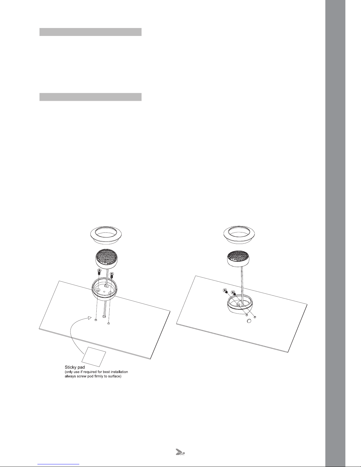
Woofer Installation
Before commencing installation, please check that the speakers you have bought will fit into the
intended hole.
Before drilling or cutting any holes please investigate the layout of your vehicle.
If possible keep the speakers away from any wiring harnesses, brake lines, fuel lines or the fuel
tank. If this is not possible then extra care and attention should be taken when cutting / drilling any
holes in the vehicle.
Ensure that the speaker when fitted will not catch on any moving parts such as door / window
handles.
If mounting in a door check that the window can still be fully lowered before installing.
Using the template provided find a suitable mounting location for the woofer.
Mark the mounting holes and pre drill the fixing hole with a 2mm drill bit.
If the grill is too be fitted then place it over the speaker and screw through both the grill and the
speaker using the provided screws. Be careful not to over tighten the screws as it may cause the
grill to break.
2
The tweeter can either be fitted flush mount or surface mount. Try and take into account the
following when locating a suitable position.
For optimum staging try and locate a position that is higher than the woofer but within twelve inches
(maximum) of it.
It is vital that the tweeter is adjusted so that it is focused towards the listener.
After finding a suitable position for the tweeters place the base of the tweeter casing in the correct
position.
Using this base mark the two mounting holes and the hole for the wire to pass through.
Cut out these holes using a 2mm drill for the fixing screws and at least an 8mm hole for the cable,
ensure that the hole cut for the cable is big enough and will not cause the cable to become chaffed
in any way.
Pass the tweeter cable through the bottom of the case and through the previously drilled hole.
Secure the bass of the tweeter housing with the screws provided.
Finally, angle the tweeter so that it is focused towards the listener.
Tweeter Installation Guideline
Surface Mount Tweeter Installation
3
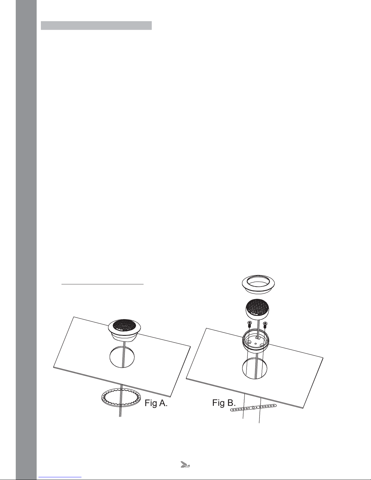
Flush Mount Tweeter Installation
For ease of installation there are two ways of fixing the tweeters in place.
The first requires the use of the metal ring provided. (See Figure A)
● After finding a suitable position for the tweeters place the cut out template for the tweeter in
position and mark around it.
● Before cutting the holes double check that no brake, fuel lines or wiring harnesses are likely
to get damaged.
● Ensure that the tweeter when fitted will not catch on any moving parts such as door / window
handles.
● If mounting in a door check that the window can still be fully lowered before installing.
● Cut out the hole carefully.
●Place the entire tweeter into the cut out hole.
● From the back push the metal ring over the rear of the casing until it is tight into the hole.
The second requires the use of the metal strip provided. (See Figure B)
● After finding a suitable position for the tweeters place the cut out template for the tweeter in
position and mark around it.
● Before cutting the holes double check that no brake, fuel lines or wiring harnesses are likely
to get damaged.
● Ensure that the tweeter when fitted will not catch on any moving parts such as door / window
handles.
● If mounting in a door check that the window can still be fully lowered before installing.
● Cut out the hole carefully.
● Position the metal strip fixing strip centrally, behind the cut out hole.
● Using the fixing screws attach the base of the tweeter case to the metal strip.
● Pass the tweeter cable through the hole in the centre in the bottom of the case and the metal
fixing strip.
● Pull the cable tight until the tweeter sits in the base.
● Screw the top of the tweeter casing to the base.
● Caution do not over tighten.
4
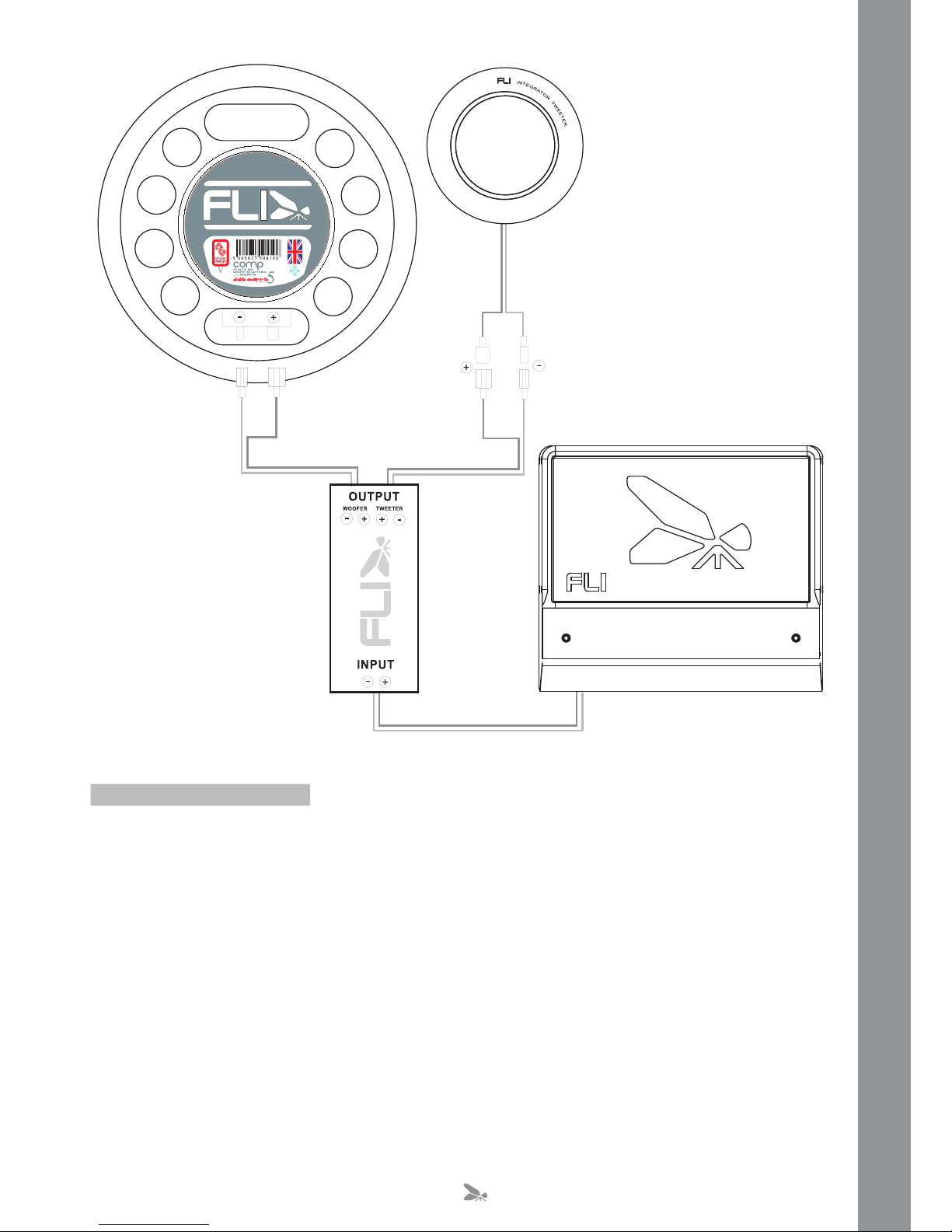
The crossover units come with wires with crimped ends on already attached to them to ease the
installation process.
The image above should be used as a guide to wire the crossovers into your system.
Once the crossover has been wired correctly use the two sticky pads to fix it to a secure, dry
location.
Please spend a little time to fill in the form at the back of this manual, along with the warranty card.
Crossover Installation
5

Specification
In order to protect your purchase and aid your
warranty please fill in the following form and
keep it safe for your future reference:
Model Number:
Serial Number:
Purchased From:
Date of Purchase:
EFAS
TI
PE
EK
:e
reh
tpiecer ruoy elpatS
www.fliaudio.co.uk
255 watts peak
85 watts RMS
MIN.input 40 watts RMS
Mount depth 56mm
Mount Dia. 143mm
Magnet Dia. 80mm
225 watts peak
75 watts RMS
MIN.input 35 watts RMS
Mount depth 55mm
Mount Dia. 114mm
Magnet Dia. 80mm
FI-COMP 6
FI-COMP 5
165 watts peak
55 watts RMS
MIN.input 25 watts RMS
Mount depth 16mm
Mount Dia. 45mm
Magnet Dia. N/A
FI-COMP 1
6

Specification
In order to protect your purchase and aid your
warranty please fill in the following form and
keep it safe for your future reference:
Model Number:
Serial Number:
Purchased From:
Date of Purchase:
EFAS
TI
PE
EK
:e
reh
tpiecer ruoy elpatS
www.fliaudio.co.uk
255 watts peak
85 watts RMS
MIN.input 40 watts RMS
Mount depth 56mm
Mount Dia. 143mm
Magnet Dia. 80mm
225 watts peak
75 watts RMS
MIN.input 35 watts RMS
Mount depth 55mm
Mount Dia. 114mm
Magnet Dia. 80mm
FI-COMP 6
FI-COMP 5
165 watts peak
55 watts RMS
MIN.input 25 watts RMS
Mount depth 16mm
Mount Dia. 45mm
Magnet Dia. N/A
FI-COMP 1
We reserve the right to make needed changes or improvements to the product ,
without informing the customer about this in advance.
Copyright
All content included in this manual such as text, graphics, logos, icons, images data, the selection and arrangement
thereof, are the property of FLI Audio (herein referred to as "FLI", "us" or "we") and its affiliate or their content and
technology providers, and are protected by United Kingdom and International copyright laws. All rights reserved.
Trademarks
FLI FrequencyTM, FLI IntegratorTM , FLI LoadedTM , FLI Trap PassiveTM, FLI Trap ActiveTM , and FLI Trap TwinTM
and all stylised representations of product names, or the abbreviations of product names, as logos are all trademarks of
FLI. Graphics and logos are trademarks or trade dress of FLI Audio or its subsidiaries.
FLI's trademarks and trade dress may not be used in connection with any product or service that is not FLI's, in any
manner that is likely to cause confusion among customers or in any manner that disparages or discredits FLI. All other
trademarks not owned by FLI or its subsidiaries that appear in this manual are the property of their respective owners,
who may or may not be affiliated with, connected to, or sponsored by FLI or its subsidiaries.
Limited Warranty
All FLI goods are covered by a full twelve months warranty. Valid from
the date of the original receipt and proof of purchase. In order to
validate this warranty, the warranty card should be returned to FLI
within seven days of the original purchase date. The original receipt
and packaging should also be kept for this twelve month period.
If at any stage during the warranty period you have a problem with the
product then it should be returned to the point of purchase in its
original packaging, complete and with no items missing.
If the store is unable to fix the product it may have to be returned to
FLI this process takes around 7 working days.
A full description of FLI's warranty information can be found on our
website:
www.fliaudio.co.uk/warranty
A written version can also be obtained from
FLI warranty department
PO Box 11000
B75 7WG
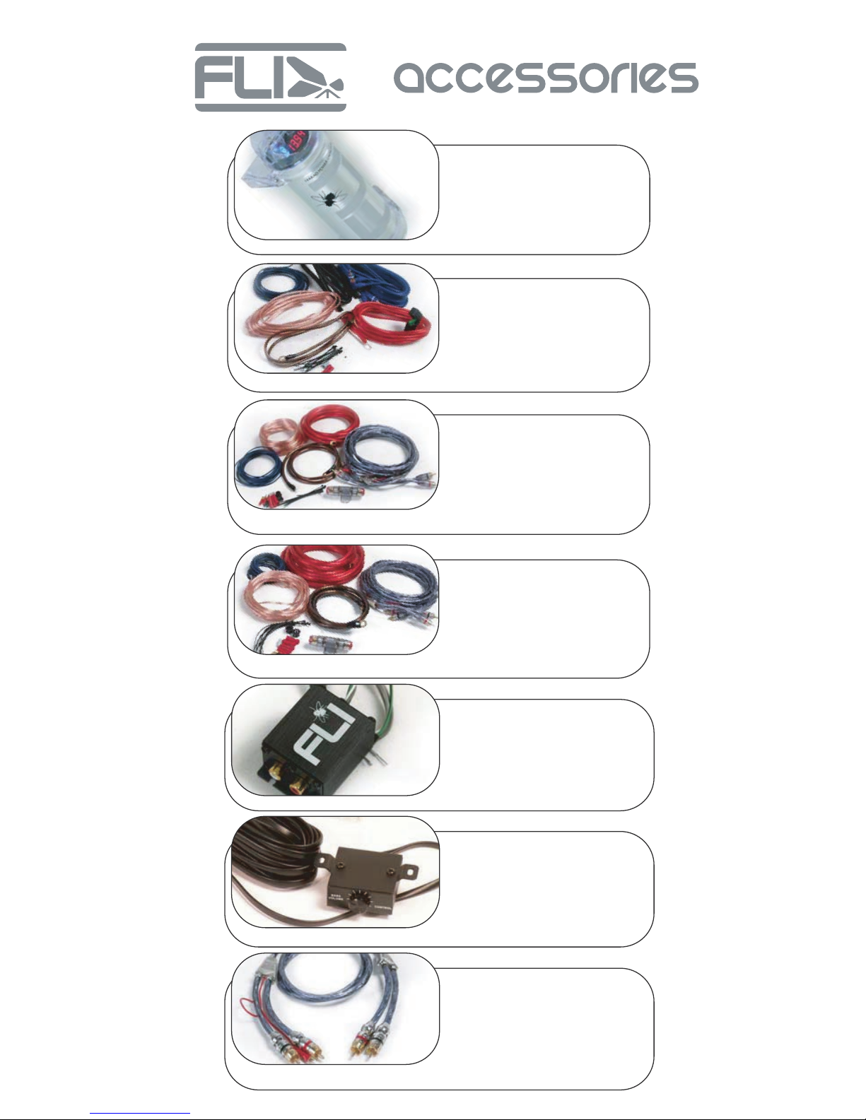
FLI Power Capacitor
The FLI powercap, a 1 farad, high
specification power capacitor is another great
addition to our range. This is an essential item
for maximum power delivery.
10 Gauge FLI Wiring Kit
For use with Car audio systems up to 1000
watts. Kit contents:
5 metre 10 AWG power cable
1 metre 10AWG ground cable
5 metre RCA interconnect
5 metre remote turn on cable
8 metre speaker cable
Inline ATC fuse holder, 30 amp ATC blade
fuse, Fitment pack,
AK8 – 8 AWG amplifier wiring kit
For use with Car audio systems up to 1500
watts Kit contents:
5 metre 8 AWG power cable
1 metre 8AWG ground cable
5 metre FIREFLI LED RCA interconnect
5 metre remote turn on cable
8 metre speaker cable
AGU glass fuse holder, 60 amp AGU glass
fuse, Fitment pack
AK4 – 4 AWG amplifier wiring kit
For use with Car audio systems up to 2000
watts Kit contents:
5 metre 4 AWG power cable
1 metre 4AWG ground cable
5 metre FIREFLI LED RCA interconnect
5 metre remote turn on cable
8 metre speaker cable
AGU glass fuse holder, 80 amp AGU glass fuse
Fitment pack
FLI Line Level Convertor
If your current head unit has no amplifier pre
outputs this FLI Line Level Convertor can be
connected directly to your rear speaker wires to
provide a stereo set of RCA connectors which
can be connected directly to an amplifier.
FLI Loaded In dash remote control
Allows 18db gain adjustment
of the bass boost feature which is present on all
FLI Loaded amplifiers. Comes complete with 5m
cable. Control can be mounted in-dash or
anywhere suitable.
dimensions: H:20mm
W:40mm D:45mm
FIREFLI LED RCA
interconnect
High quality 2 Channel RCA interconnect
featuring FIREFLI mega brite LED RCA end
plugs
Available in 1 metre and 5metre lengths and
Y-Lead configuration
This manual suits for next models
2
Table of contents
Other FLI Audio Speakers manuals


