FLI LOADED 1200m Parts list manual

Model: FLI LOADED 1200m
loaded
amplifier
www.fliaudio.co.uk

We reserve the ri
g
ht to make needed chan
g
es or improvements to the product ,
without in
f
ormin
g
the customer about this in advance.
Cop
y
ri
g
ht
All content included in this manual such as text,
g
raphics, lo
g
os, icons, ima
g
es data, the selection and arran
g
emen
t
thereo
f
, are the propert
y
o
f
FLI Audio
(
herein re
f
erred to as "FLI", "us" or "we"
)
and its a
ff
iliate or their content an
d
technolo
gy
providers, and are protected b
y
United Kin
g
dom and International cop
y
ri
g
ht laws. All ri
g
hts reserved.
T
rademark
s
FLI Frequenc
y
TM, FLI Inte
g
ratorTM , FLI LoadedTM , FLI Trap PassiveTM, FLI Trap ActiveTM , and FLI Trap TwinTM
and all st
y
lised representations of product names, or the abbreviations of product names, as lo
g
os are all trademarks o
f
FLI.
G
raphics and lo
g
os are trademarks or trade dress o
f
FLI Audio or its subsidiaries.
FLI's trademarks and trade dress ma
y
not be used in connection with an
y
product or service that is not FLI's, in an
y
m
anner that is likel
y
to cause con
f
usion amon
g
customers or in an
y
manner that dispara
g
es or discredits FLI. All other
trademarks not owned b
y
FLI or its subsidiaries that appear in this manual are the propert
y
o
f
their respective owners,
who ma
y
or ma
y
not be a
ff
iliated with, connected to, or sponsored b
y
FLI or its subsidiaries.
Limited Warrant
y
All FLI
g
oods are covered b
y
a
f
ull twelve months warrant
y
. Valid
f
rom
the date o
f
the ori
g
inal receipt and proo
f
o
f
purchase. In order t
o
validate this warrant
y
, the warrant
y
card should be returned to FL
I
within seven da
y
s o
f
the ori
g
inal purchase date. The ori
g
inal receip
t
and packa
g
in
g
should also be kept
f
or this twelve month period.
I
f
at an
y
sta
g
e durin
g
the warrant
y
period
y
ou have a problem with th
e
p
roduct then it should be returned to the point o
f
purchase in its
ori
g
inal packa
g
in
g
, complete and with no items missin
g
.
I
f
the store is unable to
f
ix the product it ma
y
have to be returned t
o
FLI this process takes around 7 workin
g
da
y
s.
A
f
ull description o
f
FLI's warrant
y
in
f
ormation can be
f
ound on our
w
ebs
it
e:
w
ww.
f
liaudio.co.uk
/
warrant
y
Awritt
e
n v
e
r
s
i
o
n
ca
n
a
l
so
be
ob
t
a
in
ed
f
r
o
m
FLI warrant
y
departmen
t
P
O
Box 11
000
B7
5
7W
G
2
Thank you for purchasing this FLI amplifier. It will provide you with a lifetime trouble free usage
providing you follow a few simple guidelines.
Mounting Guidelines
Your FLI amplifier is designed with a swift installation routine in mind. Please mount the amplifier in a dry location on a sol
id
surface. NEVER mount the amplifier upside down, this will cause the amplifier to over heat and will eventually damage the
amplifier. Before fixing the amplifier in place please ensure that there is sufficient air flow around the exterior of the casi
ng, at
least two inches is sufficient.
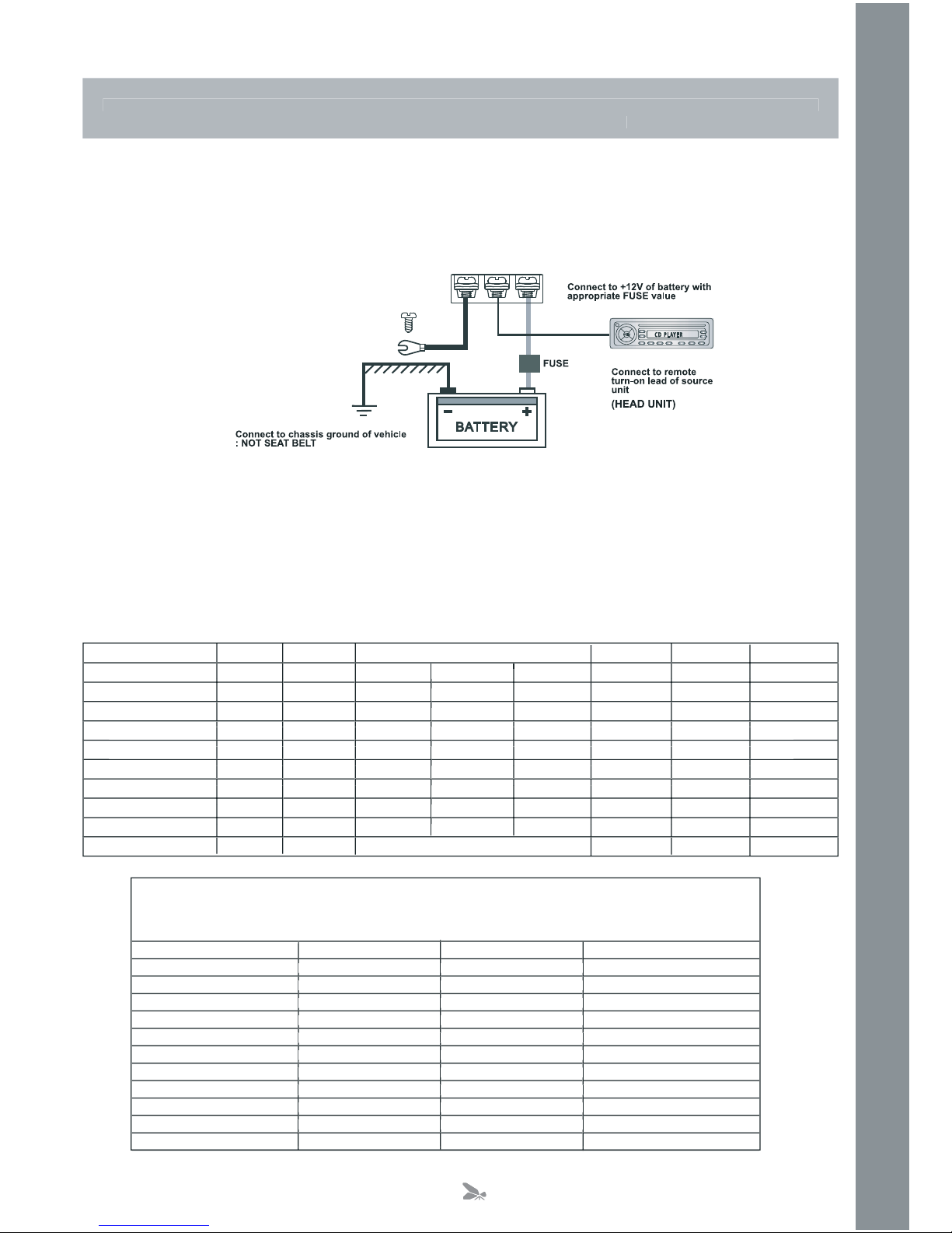
Connections
Power Cable
O
At least an 8 gauge cable should be used for both the power and the ground connections to the amplifier.
O
The power cable should be taken directly from the battery. Rubber grommets should be used when passing through any
bulkheads to prevent the cable from becoming chaffed or cut.
O
It is vital that a fuse / circuit breaker (of at least equal value to the one fitted on the amplifier) is placed inline with t
he
power cable and is
no further than eighteen inches away from the battery.
O
Please ensure that the fuse is not fitted until the entire installation procedure is complete.
O
The two tables below are to help you decide on what cable is correct for you. The first enables you to select the size of
cable depending on the length required. The second will help you convert the cable size from American Wire Gauge to
Metric if you need to.
Length of Run
Current demand 0 – 4 Ft 4 – 7 Ft 7 – 10 Ft 10 – 13 Ft 13 – 16 Ft 16 – 19 Ft 19 – 22 Ft 22 – 28 Ft
0–20 amps 14 12 12 10 10 8 8 8
20–35 amps 12 10 8 8 6 6 6 4
35–50 amps 10 8 8 6 4 4 4 4
50–65 amps 8 8 6 4 4 4 4 2
65–85 amps 6 6 4 4 2 2 2 0
85–105 amps 6 6 4 2 2 2 2 0
105–125 amps 4 4 4 2 0 0 0 0
125–150 amps 2 2 2 0 0 0 0 0
AWG to Metric Conversion Chart
cross sectional area
AWG Number Inch mm mm
2
0 0.325 8.25 53.5
1 0.289 7.35 42.4
2 0.258 6.54 33.6
3 0.229 5.83 26.7
4 0.204 5.19 21.1
5 0.182 4.62 16.8
6 0.162 4.11 13.3
7 0.144 3.66 10.5
8 0.128 3.26 8.36
9 0.114 2.91 6.63
10 0.102 2.59 5.26
0 – 4 Ft 4 – 7 Ft 7 – 10 Ft 10 – 13 Ft 13 – 16 Ft 16 – 19 Ft 19 – 22 Ft
14 12 12 10 10 8 8
12 10 8 8 6 6 6
10 8 8 6 4 4 4
88 6 4 4 4 4
66 4 4 2 2 2
66 4 2 2 2 2
44 4 2 0 0 0
22 2 0 0 0 0
0.102 2.59
1Metre–3.28Feet
3
-
Ground Cable
O
The ground cable needs to carry the same current as the power cable. At least an 8 gauge cable should be used.
O
The amplifier ground should be connected directly to the chassis of the vehicle, to bare metal.
O
The cable length should be kept to an absolute minimum.
O
It is not recommended that you connect the ground cable to the vehicles seatbelts anchor point.
Remote Turn On
O
A minimum of 18 gauge cable should be used for this connection.
O
The cable should be run with exactly the same care and attention as the power cable and taken back to the source
(headunit) and joined to the remote cable provided.
O
If the source (headunit) does not have a remote turn on cable then a 12v supply should be used. This will require a
switch to be fitted inline to enable the amplifier to be turned on and off. Remember that if this switch
is left on you will
flatten the car battery.
RCA Cables
O
Depending on the model number of your amplifier and the number of speakers you wish to power you will have to run
either one or two RCA cables from the source to the amplifier.
O
Please take extra care when running these cables
from the source to the amplifier. Ensure that they are placed away
from all items that can generate any interference, wiring harnesses etc.
O
It is recommended that the RCA cables should be run on opposite sides of the car to the previously installed power
cables, if possible.
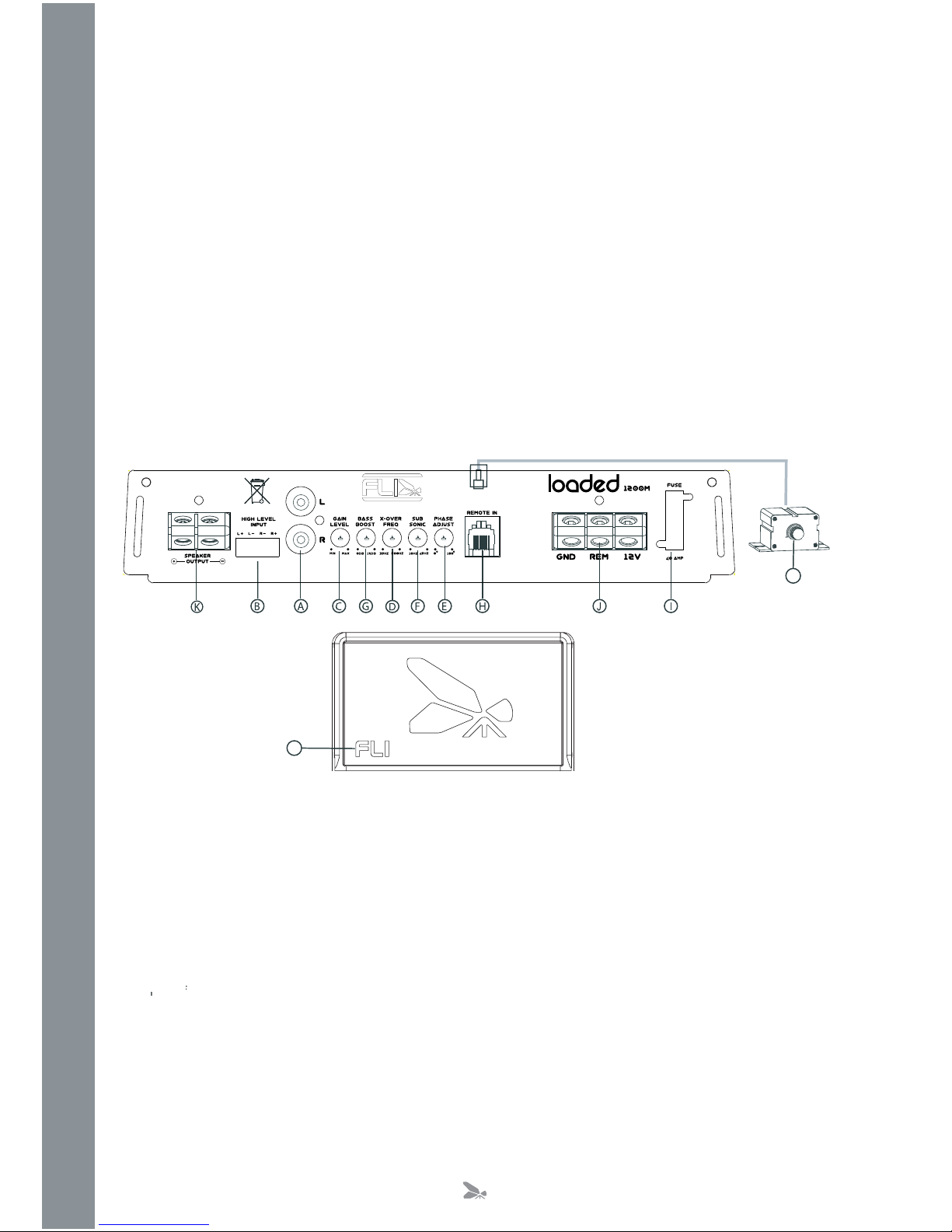
A.
Low Level Input / output
Low level input for connection to any source (headunit) with a low level output. This is your RCA output from the source
y source (headunit) with a low level output. Thi
(headunit).
Low level output for connection to another amplifier
B.
High Level Input
To be used when no RCA’s are available. Use the provided loom to connect to closest speakers. The loom provided will only
fit one way round. Once plugged in you should connect the wires this way around:
Brown
–
n
Left
–
Speaker
ft
Positive
r
Red – Left Speaker Negative
Orange
–
e
Right
–
Speaker
ht
Negative
er
Yellow
ow
Right
w
–
w
Speaker
ght
Positive
ker
C.
Gain Control
Used to match the input signal of the source (headunit) to the amplifier. See the setup section for more details.
,
4

F.
S
ub
s
oni
c
Filter
C
ontro
l
This is used to
f
ilter out unwanted ampli
f
ier output to the subwoo
f
er. E
ff
ectivel
y
this will
f
ilter out all the
f
requencies up t
o
th
e
c
rossover point set with the control. The ran
g
e is from 16 Hz to 80 Hz
G
.
B
a
ss
Boo
s
t
C
ontro
l
To provide up to an extra +12 dB o
f
bass boost at 45 Hz.
H.
B
ass Remote In
p
ut Jack
U
se to plu
g
in the remote bass controller.
I
.
Fu
s
e
Please ensure the
f
ollowin
g
f
use ratin
g
is used when replacin
g
f
uses
:
FLI Loaded 1200m – 40 amp x
1
L.
B
a
ss
Remote
C
ontroller
This remote can be mounted in the
f
ront o
f
the car and will
g
ive
y
ou the abilit
y
to raise the bass boost o
f
the ampli
f
ier
r
emotel
y
in the ran
g
e of 0 to +12 dB.
K.
Sp
eaker Terminal
O
ut
p
ut
For connection to the speakers.
S
ee Application section
f
or wirin
g
examples.
J
.Power
C
onne
c
tion
s
Power connections.
S
ee
C
onnections section
f
or details on correct connections.
S
et U
p
S
ectio
n
To correctl
y
set the
g
ain control o
f
the ampli
f
ier to match that o
f
the source
(
headunit
)
use the
f
ollowin
g
setup routine
:
Turn the
g
ain control to minimum on the ampli
f
ier.
Ensure the bass boost is set to
0
dB.
O
n the headunit set all crossovers to
f
lat and both bass and treble to zero.
Turn up the source
(
headunit
)
to approx 3
/
4 volume.
Ver
y
slowl
y
turn up the
g
ain on the ampli
f
ier until distortion can be heard in an
y
o
f
the speakers or until the volume reaches
an uncom
f
ortable listenin
g
level when this is reached turn down the
g
ain control sli
g
htl
y
.
The
g
ain control is now set.
The settin
g
of the crossover will depend on what kind of speaker
y
ou are installin
g
.
For a subwoo
f
er it is recommended that the crossover is set to Low Pass and the
f
requenc
y
is set to match that o
f
th
e
s
peakers speci
f
ications.
Note
:
B
y
usin
g
the crossovers correctl
y
y
ou will not onl
y
len
g
then the li
f
e o
f
y
our speakers but
y
ou will also
g
et better per
f
ormanc
e
f
rom them. To optimise
y
our setup seek the advise o
f
a pro
f
essional installation en
g
ineer or visit
y
our local FLI audio dealer.
D
.C
ro
ss
O
ver
C
ontro
l
Low pass
f
requenc
y
control. The
f
requenc
y
ran
g
es
f
rom 35 Hz to 500 Hz.
E
.
Pha
s
e
C
ontro
l
C
an be used to alter the phase o
f
the subwoo
f
er
f
rom 0 - 180 de
g
rees.
IE: the speaker output can be Inphase or out o
f
phase with the other speakers in the vehicle. For best results
f
lick betwee
n
the two settin
g
s to which
g
ives better low
f
requenc
y
results.
M
.Power Protect Li
g
ht
When the ampli
f
ier is operatin
g
correctl
y
the li
g
ht will illuminate constant
‘g
reen’. When the ampli
f
ier is in power protecttio
n
mode the li
g
ht will illuminate
‘
red’.
5
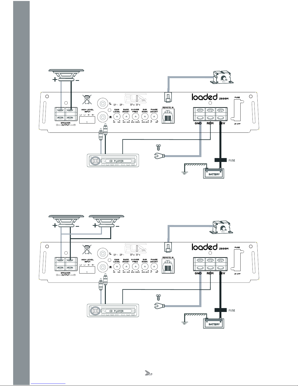
App
lication
s
-).)-5-)-0%$!.#%/HM
-).)-5-)-0%$!.#%/HM
6

T
roubleshootin
g
O
Be
f
ore removin
g
the ampli
f
ier, re
f
er to the list below and
f
ollow the su
gg
ested procedures.
O
Alwa
y
s test the speakers and con
f
irm that the
y
are wired correctl
y
f
irst.
O
I
f
in an
y
doubt
g
et help
f
rom a quali
f
ied auto electrician.
A
m
p
li
f
ier Will Not Power U
p
C
heck
f
or
g
ood
g
round connections. Ensure
G
round cable is connected directl
y
to bare metal and not a painted sur
f
ace.
U
sin
g
a multimeter check that remote terminal has at least 7V D
C
.
U
sin
g
a multimeter check that there is batter
y
volta
g
e on the positive terminal.
C
heck all
f
uses.
C
heck that the protection li
g
ht is not illuminated. I
f
it is lit, shut o
ff
the ampli
f
ier
f
or thirt
y
seconds and then turn it ba
c
k
o
n.
Protection LED Illuminates When Am
p
li
f
ier Is Powered U
p
C
heck
f
or shorts on all speakers wires.
(
i.e no speaker wires should be
j
oined to
g
ether and no speaker wires should be
touchin
g
the car’s chassis
)
O
The amplifier is desi
g
ned to shut down automaticall
y
when the units temperature
g
oes above 80 de
g
rees. If the amplifier
feels ver
y
hot then this ma
y
be the reason for the amplifier not startin
g
.
O
R
emove the speaker wires and reset the ampli
f
ier. I
f
the Protection LED still comes on then the ampli
f
ier is
f
ault
y
. This
dama
g
e ma
y
have been caused b
y
either
f
ailure to
f
ollow these setup
g
uidelines or abuse.
A
mpli
f
ier
G
ets Ver
y
Hot
C
heck the minimum speaker impedance for the amplifier is correct. This amplifier is not recommended for impedance
l
oads below 2
O
hm stereo and
/
or 4
O
hm brid
g
ed mono.
C
heck for shorts on all speakers wires.
(
i.e no speaker wires should be
j
oined to
g
ether and no speaker wires should be
touchin
g
the car’s chassis
)
C
heck that there is
g
ood air
f
low around the ampli
f
ier. In some applications an external
f
an ma
y
be required.
B
lown Fuse
(
s
)
C
heck both positive suppl
y
and
g
round for shorts.
C
heck that the positive wire is connected to the positive terminal on the ampli
f
ier.
C
heck that the ne
g
ative wire is connected to the
g
round terminal on the ampli
f
ier.
En
su
r
e
th
a
t th
e
co
rr
ec
t r
a
t
ed
fuse
i
s
f
itt
ed:
FLI Loaded 1200m – 40 amp x
1
Di
s
torted
S
ound
C
heck the
g
ain control is not set at too hi
g
h a level. I
f
the speakers sound distorted turn the down the
g
ain until the
sou
n
d
i
s
c
l
ea
r.
C
heck that all crossover frequencies are correct. See Setup section for more details.
C
heck for shorts on all speaker wires.
C
heck all speakers are wired correctl
y
. With the correct polarit
y
bein
g
observed on each connection.
7

notes

notes

In order to protect
y
our purchase and aid
y
our
warrant
y
please fill in the followin
g
form and
k
eep it safe for
y
our future reference
:
M
odel Number
:
Serial Number
:
P
urchased From
:
D
ate of Purchase
:
E
F
A
S
T
I
P
E
E
K
:
e
r
e
h
t
p
i
e
c
e
r
r
u
o
y
e
l
p
a
t
S
www.fliaudio.co.uk
Sp
eci
f
icatio
n
R
MS Power @ 13.8v D
C
Power @ 4 Ohms Mono 1 x 300 watts RMS
Power @ 2 Ohms Mono 1 x 600 watts RMS
MAX power 1200 watts
MAX power 1200 watts
Minimum speaker impedance 2 Ohms
Minimum speaker impedance 2 Ohms
THD Distortion 0.15%
IMD Distortion 0.15%
Frequency Response 20Hz - 500Hz
Frequency Response 20Hz - 500Hz
Input Sensitivity 200 mV - 7V
Input Sensitivity 200 mV - 7V
C
ro
ss
over Network
Low pass filter 35 Hz – 500 Hz
Low pass filter 35 Hz – 500 Hz
Bass Boost 0 dB - + 12 dB
Fuse rating 40A x 1
Fuse rating 40A x 1
Size length x width x height 237mm x 203mm x 55 mm
Size length x width x height 237mm x 203mm x 55 mm
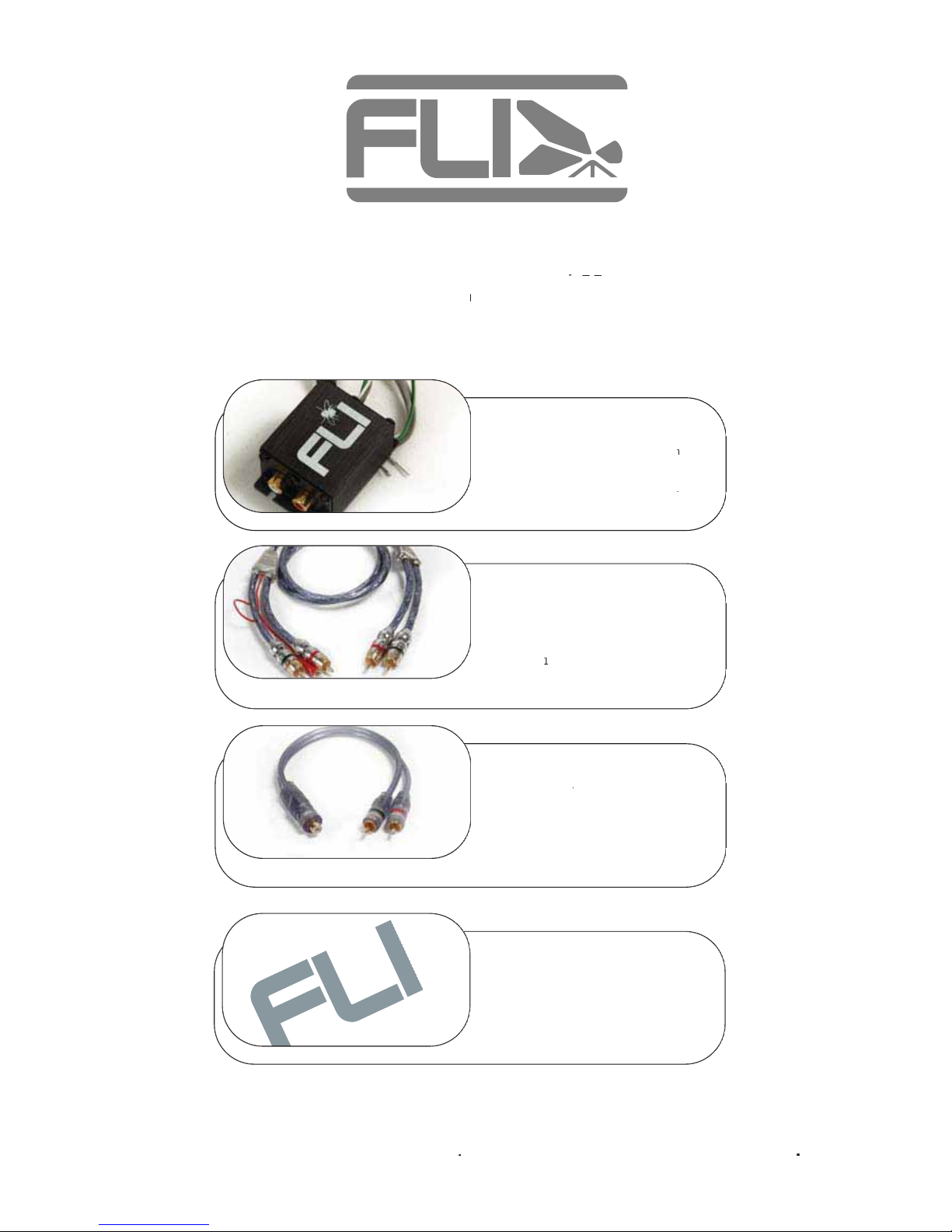
FLI Line Le
v
e
l
Co
n
v
er
t
or
I
f
yo
u
r
cu
rr
e
n
t
head
u
ni
t
has
no
r
ampli
f
ie
r
pre
outputs thi
s
FLI Lin
e
L
e
v
e
l
C
onvertor
n
can
be
co
nn
ec
t
ed
directl
y
t
o
yo
u
r
rear
s
peaker
w
ir
es
w
t
o
p
rovid
e
a
s
t
e
r
eo
set
of
RC
A
co
nn
ec
t
o
r
s
which
w
can
be
co
nn
ec
t
ed
directl
y
t
o
an
fie
amplifie
r
.
FIREFLI LED
R
C
A
inter
c
onne
c
t
H
i
gh
q
ualit
y
2
C
hannel
RC
Aint
e
r
co
nn
ec
t
featurin
g
FIREFLI
mega
b
rit
e
LED
RC
A
e
n
d
p
lu
g
s
Av
a
il
ab
l
e
i
n
1
m
e
tr
e
a
n
d
5
metr
e
l
en
g
ths
FLI
R
CA-Y
Y
inter
c
onne
c
t
H
i
gh
q
ualit
y
RC
A
Y
-lead
Y
Y
int
e
r
co
nn
ec
t
C
onverts
s
t
e
r
eo
RC
Aoutpu
t
t
o
4
c
h
a
nn
e
loutput
2
f
e
m
a
l
e
RC
A
p
lu
g
s t
o
4
ma
l
e
RC
A
p
lu
g
s
FLI
S
t
i
c
ker
s
FLI
s
ti
c
k
e
r
s
a
v
a
il
ab
l
e
i
n
whit
e
or
silver
r
5”
1
0”
1
5”
A
ccesso
ri
es
can
be
o
r
de
r
ed
separately
f
r
o
mth
e
FLI w
ebs
it
e
w
w
w
.fliaudi
p
w
w
o
.c
o
m
Onl
y
a
vailabl
e
i
nth
e
U
KIfoutsid
e
u
k
p
leas
e
c
ontac
t
yo
u
r
dealer
or
distributer
f
ro
m
th
e
FLI websit
e
Order onlin
e
or
c
al
l
sales
on
0
870 765
8
42
3
.
Al
l
i
tems
a
bov
e
come
with
f
re
e
nex
t
d
a
y
deliver
y
.

Accessories can be ordered separately from the
FLI website www.fliaudio.com
Only available in the UK If outside uk please contact your dealer or distributer from the FLI website
Order online or call sales on 0870 765 8423 . All items above come with free next day delivery.
FLI Power Capacitor
The FLI powercap, a 1 farad, high
specification power capacitor is another great
addition to our range. This is an essential item
for maximum power delivery.
10 Gauge FLI Wiring Kit
For use with Car audio systems up to 1000
watts. Kit contents:
5 metre 10 AWG power cable
1 metre 10AWG ground cable
5 metre RCA interconnect
5 metre remote turn on cable
8 metre speaker cable
Inline ATC fuse holder, 30 amp ATC blade
fuse, Fitment pack,
AK8 – 8 AWG amplifier wiring kit
For use with Car audio systems up to 1500
watts Kit contents:
5 metre 8 AWG power cable
1 metre 8AWG ground cable
5 metre FIREFLI LED RCA interconnect
5 metre remote turn on cable
8 metre speaker cable
AGU glass fuse holder, 60 amp AGU glass
fuse, Fitment pack
AK4 – 4 AWG amplifier wiring kit
For use with Car audio systems up to 2000
watts Kit contents:
5 metre 4 AWG power cable
1 metre 4AWG ground cable
5 metre FIREFLI LED RCA interconnect
5 metre remote turn on cable
8 metre speaker cable
AGU glass fuse holder, 80 amp AGU glass fuse
Fitment pack
Stores
added power
for when your
system really
needs it
For
use with
Stereo
amplifier
systems
For
use with high
power stereo
amplifier
systems
For use
with Bass
amplifier
systems
Table of contents
Other FLI Car Amplifier manuals


Popular Car Amplifier manuals by other brands


Dual
Dual illumiNITE XIA5600 Installation & owner's manual

AudioBahn
AudioBahn A2301T operating instructions

JBL
JBL CS Series owner's manual

Profile
Profile California CA1200 Installation instructions & owner's manual

Boss Audio Systems
Boss Audio Systems Riot GT880 Service manual

Philips
Philips TDA8571J datasheet