FLI LOADED 900s Parts list manual

Model: FLI LOADED 900s
loaded
amplifier
www.fliaudio.co.uk

We reserve the ri
g
ht to make needed chan
g
es or improvements to the product ,
without in
f
ormin
g
the customer about this in advance.
Cop
y
ri
g
ht
All content included in this manual such as text,
g
raphics, lo
g
os, icons, ima
g
es data, the selection and arran
g
emen
t
thereo
f
, are the propert
y
o
f
FLI Audio
(
herein re
f
erred to as "FLI", "us" or "we"
)
and its a
ff
iliate or their content an
d
technolo
gy
providers, and are protected b
y
United Kin
g
dom and International cop
y
ri
g
ht laws. All ri
g
hts reserved.
T
rademark
s
FLI Frequenc
y
TM, FLI Inte
g
ratorTM , FLI LoadedTM , FLI Trap PassiveTM, FLI Trap ActiveTM , and FLI Trap TwinTM
and all st
y
lised representations of product names, or the abbreviations of product names, as lo
g
os are all trademarks o
f
FLI.
G
raphics and lo
g
os are trademarks or trade dress o
f
FLI Audio or its subsidiaries.
FLI's trademarks and trade dress ma
y
not be used in connection with an
y
product or service that is not FLI's, in an
y
m
anner that is likel
y
to cause con
f
usion amon
g
customers or in an
y
manner that dispara
g
es or discredits FLI. All other
trademarks not owned b
y
FLI or its subsidiaries that appear in this manual are the propert
y
o
f
their respective owners,
who ma
y
or ma
y
not be a
ff
iliated with, connected to, or sponsored b
y
FLI or its subsidiaries.
Limited Warrant
y
All FLI
g
oods are covered b
y
a
f
ull twelve months warrant
y
. Valid
f
rom
the date o
f
the ori
g
inal receipt and proo
f
o
f
purchase. In order t
o
validate this warrant
y
, the warrant
y
card should be returned to FL
I
within seven da
y
s o
f
the ori
g
inal purchase date. The ori
g
inal receip
t
and packa
g
in
g
should also be kept
f
or this twelve month period.
I
f
at an
y
sta
g
e durin
g
the warrant
y
period
y
ou have a problem with th
e
p
roduct then it should be returned to the point o
f
purchase in its
ori
g
inal packa
g
in
g
, complete and with no items missin
g
.
I
f
the store is unable to
f
ix the product it ma
y
have to be returned t
o
FLI this process takes around 7 workin
g
da
y
s.
A
f
ull description o
f
FLI's warrant
y
in
f
ormation can be
f
ound on our
w
ebs
it
e:
w
ww.
f
liaudio.co.uk
/
warrant
y
Awritt
e
n v
e
r
s
i
o
n
ca
n
a
l
so
be
ob
t
a
in
ed
f
r
o
m
FLI warrant
y
departmen
t
P
O
Box 11
000
B7
5
7W
G
2
T
hank
y
ou
f
or purchasin
g
this FLI ampli
f
ier. It will provide
y
ou with a li
f
etime o
f
trouble
f
ree use
providin
g
y
ou
f
ollow a
f
ew simple
g
uidelines.
M
ountin
g
G
uideline
s
Your FLI ampli
f
ier is desi
g
ned with a swi
f
t installation routine in mind. Please mount the ampli
f
ier in a dr
y
location on a soli
d
s
ur
f
ace. NEVER mount the ampli
f
ier upside down, this will cause the ampli
f
ier to over heat and will eventuall
y
dama
g
e th
e
ampli
f
ier. Be
f
ore
f
ixin
g
the ampli
f
ier in place please ensure that there is su
ff
icient air
f
low around the exterior o
f
the casin
g
, a
t
leas
t tw
o
in
c
h
es
will
be
suff
i
c
i
e
nt.
C
onne
c
tion
s
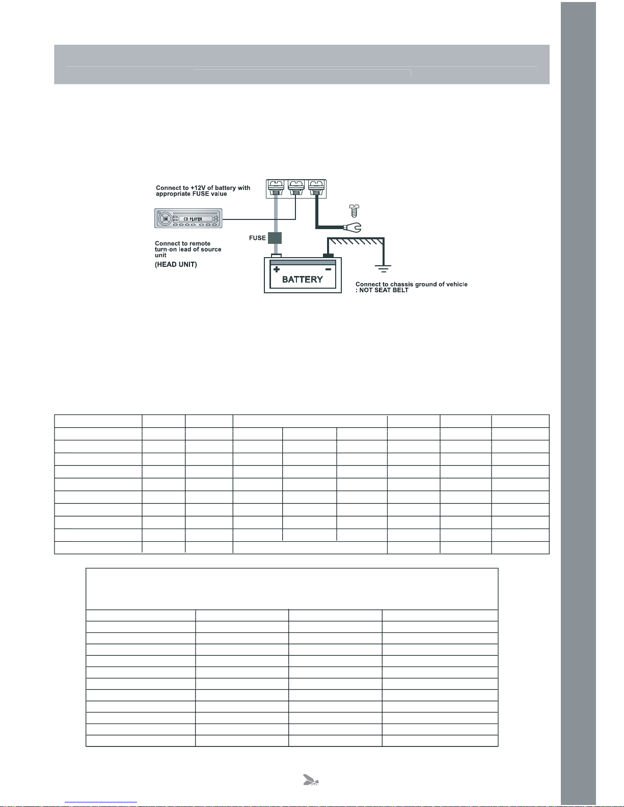
Power
C
able
O
At least an 8
g
au
g
e cable should be used
f
or both the power and the
g
round connections to the ampli
f
ier.
O
The power cable should be taken directl
y
f
rom the batter
y
. Rubber
g
rommets should be used when passin
g
throu
g
h an
y
bulkheads to prevent the cable
f
rom becomin
g
cha
ff
ed or cut.
O
It is vital that a
f
use
/
circuit breaker
(
o
f
at least equal value to the one
f
itted on the ampli
f
ier
)
is placed in line with
t
h
e
p
ower cable and is no
f
urther than ei
g
hteen inches awa
y
f
rom the batter
y
.
O
Please ensure that the
f
use is not
f
itted until the entire installation procedure is complete.
O
The two tables below are to help
y
ou decide on what cable is correct
f
or
y
ou. The
f
irst enables
y
ou to select the size o
f
c
able dependin
g
on the len
g
th required. The second will help
y
ou convert the cable size
f
rom American Wire
G
au
g
e to
M
etric if
y
ou need to.
Len
g
th o
f
Ru
n
Current demand 0 – 4 Ft 4 – 7 Ft 7 – 10 Ft 10 – 13 Ft 13 – 16 Ft 16 – 19 Ft 19 – 22 Ft 22 – 28 Ft
0 – 4 Ft 4 – 7 Ft 7 – 10 Ft 10 – 13 Ft 13 – 16 Ft 16 – 19 Ft 19 – 22 Ft
0–20 amps 14 12 12 10 10 8 8 8
14 12 12 10 10 8 8
20–35 amps 12 10 8 8 6 6 6 4
12 10 8 8 6 6 6
35–50 amps 10 8 8 6 4 4 4 4
10 8 8 6 4 4 4
50–65 amps 8 8 6 4 4 4 4 2
88 6 4 4 4 4
65–85 amps 6 6 4 4 2 2 2 0
66 4 4 2 2 2
85–105 amps 6 6 4 2 2 2 2 0
66 4 2 2 2 2
105–125 amps 4 4 4 2 0 0 0 0
44 4 2 0 0 0
125–150 amps 2 2 2 0 0 0 0 0
22 2 0 0 0 0
AW
G
to Metric
C
onversion
C
har
t
c
r
oss
sec
ti
o
n
a
l
a
r
ea
AW
G
Number Inch mm mm
2
0 0.325 8.25 53.5
0.325 8.25
1 0.289 7.35 42.4
0.289 7.35
2 0.258 6.54 33.6
0.258 6.54
3 0.229 5.83 26.7
0.229 5.83
4 0.204 5.19 21.1
0.204 5.19
5 0.182 4.62 16.8
0.182 4.62
6 0.162 4.11 13.3
0.162 4.11
7 0.144 3.66 10.5
0.144 3.66
8 0.128 3.26 8.36
0.128 3.26
9 0.114 2.91 6.63
0.114 2.91
10 0.102 2.59 5.26
0.102 2.59
1Metre–
3
.2
8
Fee
t
3
G
round
C
able
O
The
g
round cable needs to carr
y
the same current as the power cable. At least an 8
g
au
g
e cable should be used.
O
The ampli
f
ier
g
round should be connected directl
y
to the chassis o
f
the vehicle, to bare metal.
O
The cable len
g
th should be kept to an absolute minimum.
(
NB
)
I
t
is not recommended that
y
ou connect the
g
round cable to the vehicles seatbelts anchor point.
Remote Turn
On
O
A minimum o
f
18
g
au
g
e cable should be used
f
or this connection.
O
The cable should be run with exactl
y
the same care and attention as the power cable and taken back to the source
(
headunit
)
and
j
oined to the remote cable provided.
O
I
f
the source
(
headunit
)
does not have a remote turn on cable then a 12v suppl
y
should be used. This will require a
s
witch to be fitted inline to enable the amplifier to be turned on and off. Remember that if this switch is le
f
t on
y
ou will
f
latten the car batter
y
.
R
C
A
C
able
s
O
Dependin
g
on the model number o
f
y
our ampli
f
ier and the number o
f
speakers
y
ou wish to power
y
ou will have to run
e
ither one or two R
C
A cables
f
rom the source to the ampli
f
ier.
O
Please take extra care when runnin
g
these cables
f
rom the source to the ampli
f
ier. Ensure that the
y
are placed awa
y
f
rom all items that can
g
enerate an
y
inter
f
erence, wirin
g
harnesses etc.
O
It is recommended that the RCA cables should be run on the opposite site of the car to the previousl
y
installed power
c
ables, i
f
possible.
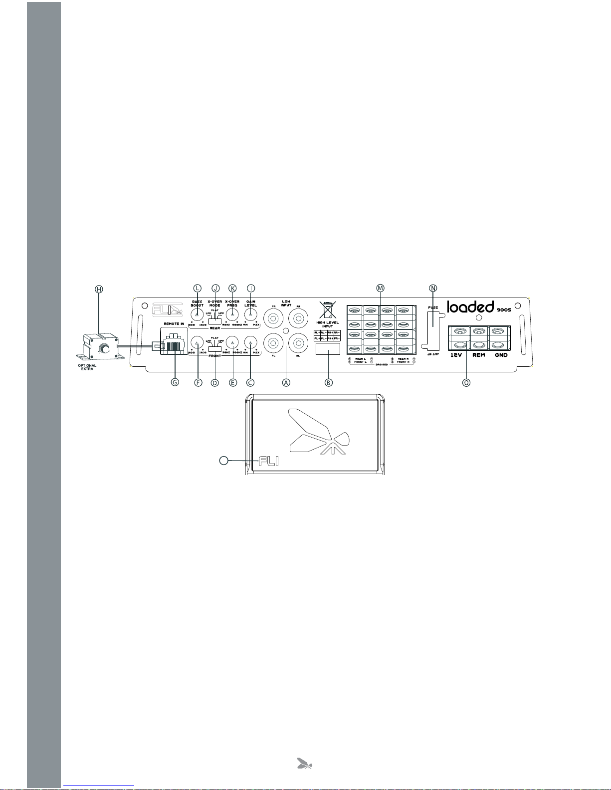
A
.Low Level In
p
ut
For connection to any source (headunit) with a low level output. This is your RCA output from the source (headunit).
a low level output. This is
y
our R
C
A out
p
B
.Hi
g
h Level Input
To be used when no R
C
A’s are available. Use the provided loom to connect to closest speakers. The loom provided will onl
y
f
it one wa
y
round.
O
nce plu
gg
ed in
y
ou should connect the wires this wa
y
around
:
Brown
wn
Front
–
Right
nt
Speaker
ht
P
os
itiv
e
e
r
Black – Front Ri
g
ht
S
peaker Ne
g
ativ
e
Orange
– Front Left Speaker Negative
e
Y
e
ll
ow
– Front Left Speaker Positive
w
Blue – Rear Ri
g
ht Speaker Positiv
e
Green – Rear Ri
g
ht Speaker Ne
g
ativ
e
Grey
– Rear Left Speaker Negative
Whit
– Rear Left Speaker Positive
e
C
.
C
hannel
1
/
2
G
ain
C
ontro
l
U
sed to match the input si
g
nal o
f
the source
(
headunit
)
to the ampli
f
ier.
S
ee the setup section
f
or more details.
D
.C
hannel
1
/
2
C
ro
ss
O
ver
S
ele
c
t
S
wit
ch
U
sed to select between Flat, Hi
g
h Pass Filter and Low Pass Filter.
The hi
g
h pass filter will onl
y
allow hi
g
h frequenc
y
information to be passed to the speaker
(
s
)
while the low pass filter will
o
nl
y
allow low
f
requenc
y
in
f
ormation to be sent.
If no filter needs to be applied then place the switch in the
f
lat position.
P
4

E
.C
hannel
1
/
2
C
ross
O
ver Frequenc
y
C
ontro
l
H
i
g
h pass
f
requenc
y
control. The
f
requenc
y
ran
g
es
f
rom 50 Hz to 500 Hz.
F.
C
hannel
1
/
2
Ba
ss
Boo
s
t
C
ontro
l
To provide up to an extra +12 dB o
f
bass boost at 45 Hz. Use this boost to increase bass output
f
rom the ampli
f
ier.
G
.
B
ass Remote In
p
ut
S
ocket
U
se to plu
g
in the optional remote bass controller.
H.
Op
tional Bass Remote
C
ontroller
This remote can be mounted in the
f
ront o
f
the car and will
g
ive
y
ou the abilit
y
to raise the bass boost o
f
the ampli
f
ier
r
emotel
y
in the ran
g
e o
f
0 to +12 dB.
The
y
can be purchased separatel
y
f
rom the FLI website www.
f
liaudio.co.uk, see back pa
g
e
f
or more details.
I.
C
hannel
3
/
4
G
ain
C
ontro
l
U
sed to match the input si
g
nal o
f
the source
(
headunit
)
to the ampli
f
ier.
S
ee the setup section
f
or more details.
J
.C
hannel
3
/
4
C
ro
ss
O
ver
S
ele
c
t
S
wit
ch
U
sed to select between Flat, Hi
g
h Pass Filter and Low Pass Filter.
The hi
g
h pass filter will onl
y
allow hi
g
h frequenc
y
information to be passed to the speaker
(
s
)
while the low pass filter will o
n
l
y
allow low
f
requenc
y
in
f
ormation to be sent.
I
f
no
f
ilter needs to be applied then place the switch in the
f
lat position.
K
. Channel 3 / 4 Cross Over Frequency Control
K
K
H
i
g
h pass
f
requenc
y
control. The
f
requenc
y
ran
g
es
f
rom 50 Hz to 500 Hz.
L.
C
hannel
3
/
4
Ba
ss
Boo
s
t
C
ontro
l
To provide up to an extra +12 dB o
f
bass boost at 45 Hz. Use this boost to increase bass output
f
rom the ampli
f
ier.
M
.
Sp
eaker Terminal
O
ut
p
ut
For connection to the speakers.
S
ee application section
f
or wirin
g
examples.
N
.
Fu
s
e
Please ensure the
f
ollowin
g
f
use ratin
g
is used when replacin
g
f
uses
:
FLI Loaded 900s – 40 am
p
O
.Power
C
onne
c
tion
s
Power connections.
S
ee connections section
f
or details on correct connections.
P. Power Protect Li
g
ht
When the ampli
f
ier is operatin
g
correctl
y
the li
g
ht will illuminate constant
‘g
reen’. When the ampli
f
ier is in power protectti
o
n
m
ode the li
g
ht will illuminate
‘
red’.
5
Other manuals for LOADED 900s
1
Table of contents
Other FLI Car Amplifier manuals


