Addictive audio 5.2 User manual

5.2
STEREO/MONO BRIDGEABLE
HIGH POWER CAR AMPLIFIER
INSTRUCTION MANUAL
PLEASE READ THIS MANUAL BEFORE INSTALLATION AND USING AMPLIFIER

Congratulations!
• Class ''AB''Technology MOSFET PWM Power Supply.
• Bridgeable &TRI-Mode Operation.
• Continuously Variable 12dB/Octave HighPass & 12dB
• SILVER Plated RCA
• High Q Power & SpeakerBlock Terminal.
• Soft Start& Muting.
• Overload, Thermal, DC off set andShort Circuit Protection.
• Power &Protection indicator.
uality
Features
- 2 -
And thank you for choosing this car audio amplifier! To maximize the performance of this
amplifier and your car audio system install, we recommend that you acquaint yourself
thoroughly with all capabilities and features of the amplifier model you have chosen.
Please read this manual carefully, before attempting the installation of this amplifier.
Please retain this manual and your purchasing / installation receipts for future reference.
In case you are installing your amplifier by yourself, you should have your
installation checked and approved by an authorized professional dealer /
installer, in order to qualify for full warranty protection and also, to reach
maximum power-output and audio performance possible with your individual
IMPORTANT NOTICE:
car audio system.

4CAR AUDIO AMPLIFIER :
This amplifier allows the crossover controlled amplification of satellite speaker systems,
kickwoofer or subwoofer systems
4FULL-MOSFET CIRCUITRY :
This amplifier line features a full MOS-FET circuitry layout, implementing MOS-FET's
for power supply, to guarantee excellent sonic performance and very high power output
4LOAD STABILITY :
This amplifier line up features models that work stable and reliable into very low
impedance loads. Due to the high damping factor, every model of this amplifier line will
guaranteed to have full control over the connected speaker system(s)
4INTEGRATED ELECTRONIC CROSSOVER :
The internal crossover section features independently selectable highpass filtering, as
well as full range loop through. All x-overs feature crossover slope rates of 12 dB/octave
4UNCOMPROMISING DESIGN AND CONSTRUCTION :
Only best electrical and electronic components have been used for the assembly of
this amplifier line.
4ADVANCED PROTECTION CIRCUITRY :
The protection circuitry safe-guards the amplifier from short-circuits at the speaker
outputs, DC offset voltage at the outputs and overheating of power electronics
4STATUS AND PROTECTION LED'S:
A green and a red LED located at the side panel enable you to monitor the operating
status of your amp
4ADJUSTABLE INPUT SENSITIVITY :
in order to achieve maximum signal-to-noise performance "LEVEL" control adjusts
the signal level from your headunit to match the amplifier's sensitivity.
IT IS NOT A VOLUME OR POWER CONTROL!!
To adjust, proceed as follows:
a. Set input "LEVEL" control to "MIN".
b. Turn your headunit's volume to maximum level. If distortion is heard decrease
headunit's volume until the sound is clear.
c. Turn the "LEVEL" control toward "MAX" in stages, until the onset of audible distortion
is heard, then decrease to level prior to the point of audible distortion.
NOTE:
not performing above adjustment procedure and/or simply setting "LEVEL"
control at or near "MAX" position, may induce electrical audio noise into the
system or break down of the amplifier because driving the amplifier to distortion.
DESIGN FEATURES
- 3 -

1. RCA INPUTS 1/2-CH
Low-level stereo RCA signal input for connection with head-unit..
2.INPUT LEVEL CONTROL
Input level control for amplifier section-allowing to match the output voltage of the
head-unit's RCA line-outs to the amplifier input section.
3.
4.
5.HIGH PASS FREQUENCY CONTROL
Control for the frequency adjustment of the 12dB/oct. high-pass filtering of the
speakers connected to output terminals.
AMPLIFIER ACTIVE X-OVER SWITCH
a) FULL: Allows for full range pass through.
b) High position (HPF): Allows for the control of the high pass frequency range
(50Hz-500Hz) by using the high Variable Control.
AMPLIFIER ACTIVE HPF RANGE SELECT SWITCH
High position (HPF): Allows for the control of the high pass frequency range
(50Hz-5KHz) by using the high Variable Control.
CONNECTIONS & CONTROLS
FRONT PANEL
L
R
MIN MAX 50Hz
(500Hz)
500Hz
(5kHz)
FULL H.P.F
x 10
x 1
LINE INPUT LEVEL HIGH PASS FILTER
5.2
2 CHANNEL CLASS AB AMPLIFIER
- 4 -

CONNECTIONS & CONTROLS
REAR PANEL
6.POWER LED
Green"Operation" LED, signaling correct operation of the amplifier.
7.PROTECTION LED
Red "Protection" LED, signaling faulty speaker connections or general malfunction of
the amplifier.
8."GND" POWER INPUT TERMINAL
Terminal to connect the amplifier to the negative or ground pole of the car battery.
9."REM" REMOTE INPUT TERMINAL
Terminal to connect the amplifier to the automatic (remote) turn-on / turn-off lead of
the head unit.
10."B+" POWER INPUT TERMINAL
Terminal to connect the amplifier to the positive +12V pole of the car battery.
11.FUSE
Fuses protect amplifier from high current so that amplifier works safely.
12.SPEAKER OUTPUT TERMINALS 1/2-CH
Output terminals to connect the speakers in stereo or bridged mode to the amplifier.
- 5 -
POWER FUSE
GND REM B+
BRIDGED
CH1 CH2
ON
PROT
SPEAKER
2 CHANNEL CLASS AB AMPLIFIER 5.2

Attention! For your own safety, disconnect the positive battery terminal (+12v) or
remove the main fuse in the positive power cable near the car battery, before you
start any wiring work!
AMPLIFIER MOUNTING
- 6 -
Before you proceed to install this amplifier, it is recommended to map out the complete
audio system and the respective wiring required. Consider all additional electrical
requirements and accessories, such as power cables, interconnect cables etc., to
complete this install. Please note that because of possible interference problems with
the existing car electrics and electronics especially the routing of the signal cables and
the chassis ground connection will have a profound impact on the trouble free
(noise free!) operation of the amplifier.
The mounting location should be carefully selected and in the interest of passive driver
and passenger safety, the amplifier must be securely mounted. Make sure that there is
no wiring harness, fuel tank etc. behind or below the mounting surface, that may be
damaged by the drilling of the holes for the amplifier mounting screws. After installation,
there should be a clearance of at least 5cm to all sides including the top of the amplifier
heatsink. Make sure the unit is not exposed to direct sunlight, humidity, water, oil or spill
of other fluids that may enter the amplifier.
Once the location where the amplifier will be mounted is defined, use the unit as a template
for the marking of the mounting holes with pencil or felt-tip marker. The mounting holes
should be pilot-drilled, using a 2,5mm or 3mm drill bit. For the actual mounting, always
use the supplied rubber washers before attaching the amp to the panel with the supplied
mounting screws.
Self Tapping Screws

(1) GROUND: To Vehicle Chassis
To avoid unwanted ignition noise caused by ground loops, it is essential that the amplifier
be grounded to a clean, bare, metal surface of the vehicle's chassis
CAUTION:
AS A PRECAUTION, IT IS ADVISABLE TO DISCONNECT THE VEHICLE'S BATTERY
BEFORE MAKING CONNECTION TO THE +12 VOLT SUPPLY WIRING.
WIRING CONNECTIONS
- 7 -
33/20/10mm² depending from the model(thicker if planning for additional amplifier) wire
is recommended for both the power and ground wires. 12 Gauge, for the remote turn-on
wire. Both types are available at most Mobile Audio Dealers or Installation Shops.
NOTE:
If your radio does not have a +12 Volt output lead when the radio is turned ON,
the "RMT" terminal on the Amplifier can be connected to vehicle's accessory
circuit that is live when the key is "ON".
NOTE:
GROUND WIRE SHOULD NOT BE EXTENDED MORE THAN 3FT(1 METER)
(3) Remote Turn-On Input: To Power Antenna output of Car Stereo This Amplifier is turned
"ON" remotely when the vehicle's stereo is turned "ON".
(2) +12 Volt(Fuse) Constant Power: To Battery(+)
Due to the power requirements of the Amplifier, this connection should be made directly
to the positive(+) terminal of battery. For safety measures, install an in-line Fuse Holder
(not included) as close to the battery positive (+) terminal as possible with an ampere
rating; not to exceed total value of fuses in Amp.

L
R
MIN MAX 50Hz
(500Hz)
500Hz
(5kHz)
FULL H.P.F
x 10
x 1
LINE INPUT LEVEL HIGH PASS FILTER
5.2
2 CHANNEL CLASS AB AMPLIFIER
WIRING DIAGRAM
2 CHANNEL
- 8 -
CH2
CH1
GND REM B+
AUTO - ANTENNA LEAD
CAR STEREO HEAD UNIT
CROSSOVER ADJUSTMENTS
To reach a maximum in dynamic response from each individual head-unit/amplifier/
speaker combination, it is important to set the respective input level controls "GAIN"
of all channel pairs correctly.
Before you start, you MUST set all tone controls (Bass, Mid, Treble, Loudness etc.)
and the fader on the head unit to their neutral or center positions.
Now turn all input gain controls of the installed amplifiers anti-clockwise to their minimum
positions and start with the channel pair, that drives the subwoofer system. The lowpass
level remote control if installed in your system configuration - should be set at a low position,
so there is enough headroom to turn up the bass volume later on.
INPUT LEVEL ADJUSTMENT
POWER FUSE
GND REM B+
BRIDGED
CH1 CH2
ON
PROT
SPEAKER
2 CHANNEL CLASS AB AMPLIFIER 5.2
POWER FUSE
GND REM B+
BRIDGED
CH1 CH2
ON
PROT
SPEAKER
2 CHANNEL CLASS AB AMPLIFIER 5.2
POWER FUSE
GND REM B+
BRIDGED
CH1 CH2
ON
PROT
SPEAKER
2 CHANNEL CLASS AB AMPLIFIER 5.2
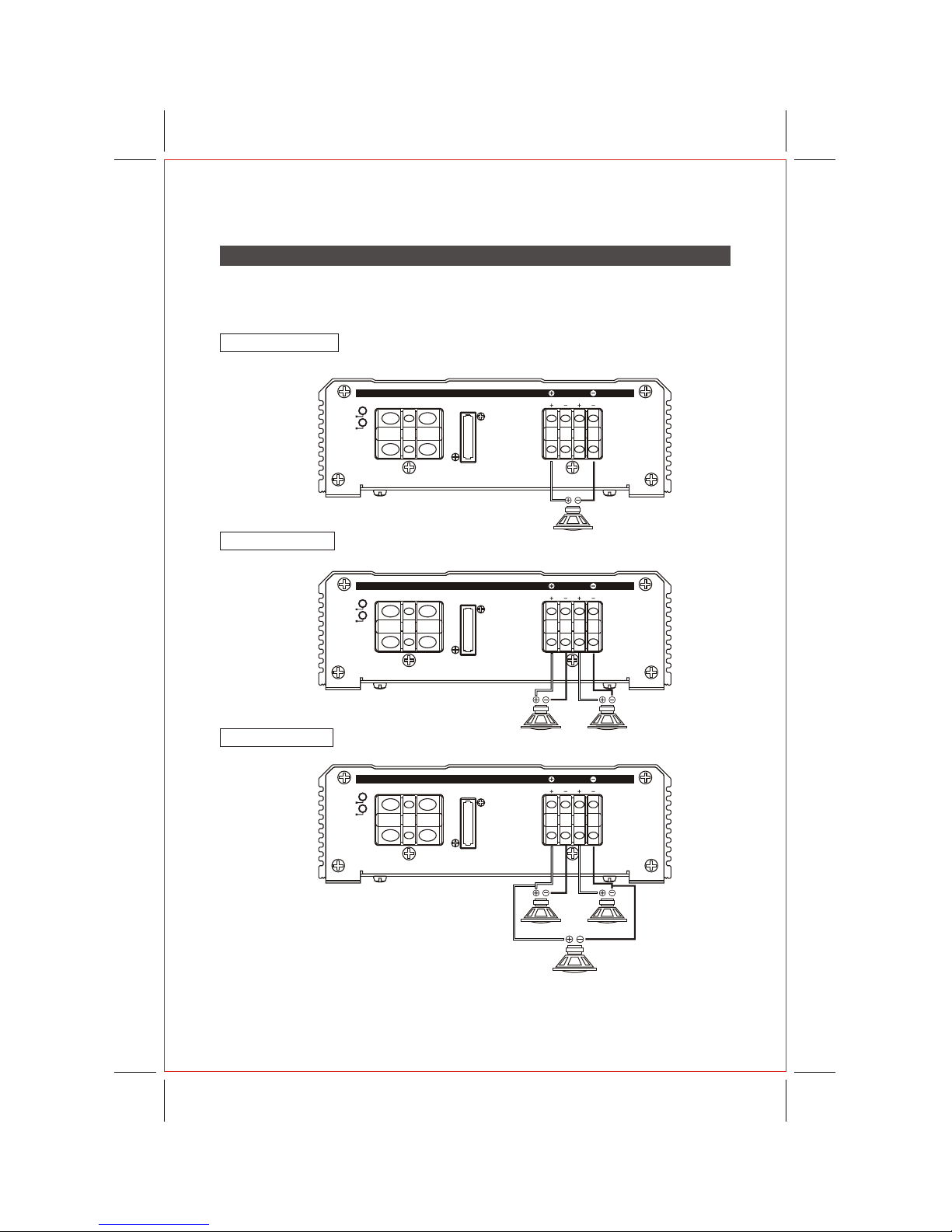
SYSTEM WIRING DIAGRAM
1 SPEAKER BRIDGED
2 SPEAKER STEREO
3 SPEAKER TRI-MODE
- 9 -
2 CHANNEL SPEAKER CONNECTIONS
4 Ohms
3 CH (SUB WOOFER)
8 Ohms
1CH
4 Ohms
1CH
2-4 Ohms
2CH
2-4 Ohms
1CH 2CH

- 10 -
We have put together this trouble-shooting guide if you experience problems after
installing the amplifier. Please keep in mind that the majority of problems incurred are
caused by improper installation and not the equipment itself. In addition, there are many
components in the system that could cause various signal problems such as inducted
LOOK FOR.... SOLUTION
No Output
Blown fuse Replace
Bad RCA Cable(s) Replace
+12V at power terminal Check connection
+12V at remote terminal Check connection
Grounding point clean and tight Check for ground w/meter
Head Unit's fader not in center position Set to center position
Low Output
Check level adjustments Re-adjust
Bad RCA cable(s) Replace
Improper level matching Re-adjust
Engine Noise
Grounding points are clean and tight Check for ground w/meter
Ground all components at same point Ground at same point
Try different grounding point Change for better ground
Bad RCA cable(s) Replace
Use High Quality shielded RCA cables Rejects inducted noise
Low Vehicle charging system and/or battery Fix and/or replace
Protection L.E.D. Illuminated
Speaker short Check speakers connection
for short circuit
Speaker grounding out Make sure speaker wires
do not touch chassis ground
Impedance too low Check speaker impedance
(Min 2 ohm Stereo, 4 ohm Bridged)
Overheating Check mounting location
for adequate air circulation.
Speaker impedance too low
TROUBLE SHOOTING THE SYSTEM
electrical noise and engine noise.
Before you can properly address the problem, you must first find the component that is
causing the problem. This will take patience and a process of elimination.
- 11 -
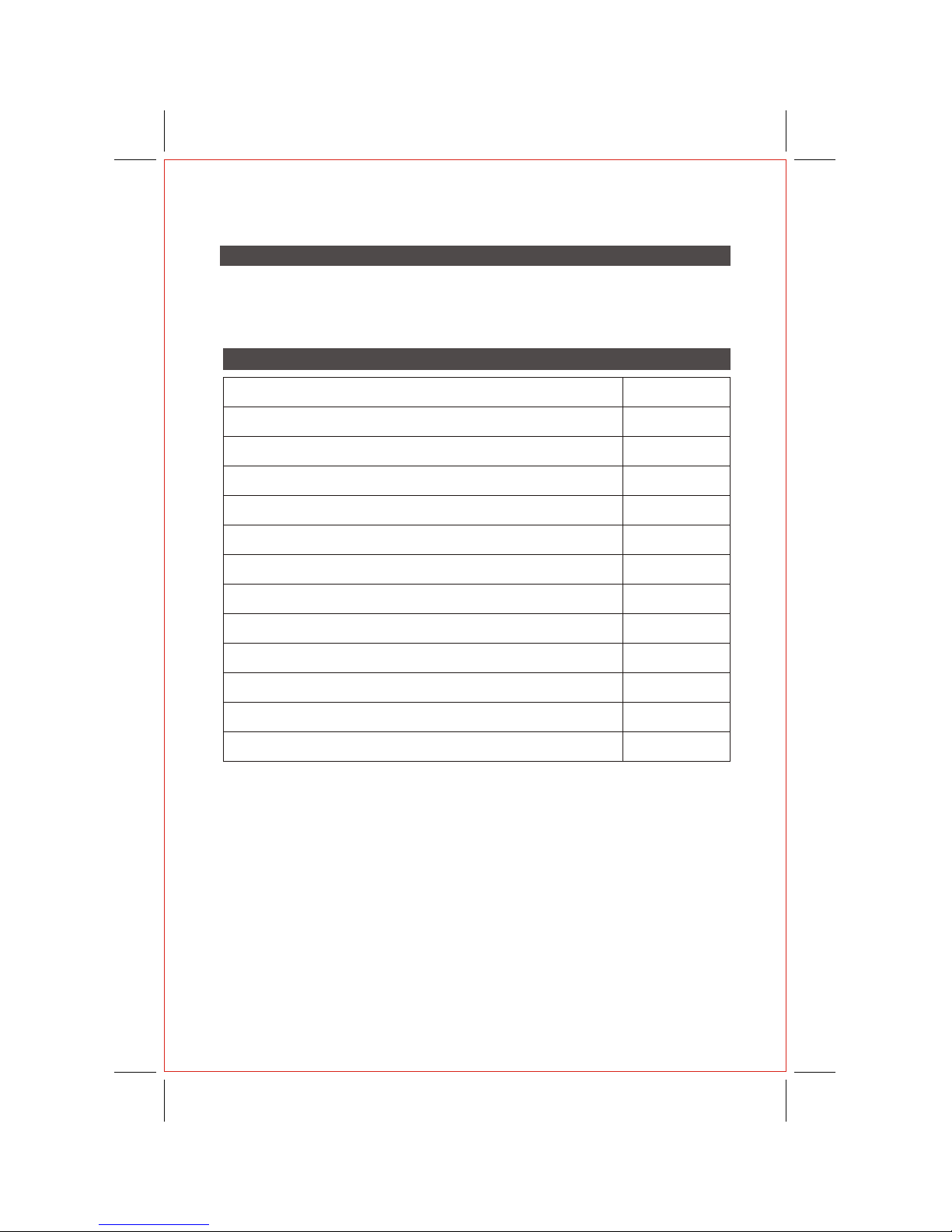
SPECIFICATION
NOTE :
Specifications & design subject to change without notice for improvements.
4OHM @ 0.08% THD STEREO RMS
2OHM @ 0.08% THD STEREO RMS
4OHM @ 0.08% THD MONO RMS
EFFICIENCY
HIGH PASS FILTER(VARIABLE)
FREQUENCY RESPONSE (-1dB)
SIGNAL TO NOISE RATIO (`A' WTD)
INPUT SENSITIVITY
INPUT IMPEDANCE
OPERATION VOLTAGE (NEGATIVE GROUND)
SPEAKER IMPEDANCE @ STEREO DRIVEN
FUSE RATING
DIMENSIONS (W mm x H mm x D mm )
AMPLIFIER
5.2
65X2
100X2
190X1
80%
50Hz-5KHz
10Hz-30kHz
>103dB
200mV - 6V
10k Ohms
DC 12V
4 Ohms
20A x 1
152 x 49 x 150

Table of contents


