Flintec FAA-26 User manual
FAA-26
Analogue Amplifier
Technichal Manual
www.flintec.com

FAA-26, Technical Manual, Rev. 1.2.0, December 2020 Page 2of 14
Table of Contents
1. Safety Instructions...........................................................................3
2. Declaration of Conformity................................................................4
3. Front View, Features and Specifications..........................................5
4. Installation and Commissioning.......................................................7
4.1 Mechanical Installation..................................................................8
4.2 Load Cell Connection....................................................................8
4.3 Analogueue Output Connection....................................................9
4.4 Changing the Analogueue Output Type........................................9
4.5 Commissioning ...........................................................................10
5. Adjustments...................................................................................11
5.1 Adjustment with rotary switch......................................................11
5.2 Adjustment at PLC......................................................................12
5.3 Testing the Scale Performance...................................................12
6. Operation.......................................................................................13
7. Trouble Shootıng ...........................................................................14

FAA-26, Technical Manual, Rev. 1.2.0, December 2020 Page 3of 14
RIGHTS AND LIABILITIES
1. Safety Instructıons
CAUTION READ this manual BEFORE operating or servicing this equipment.
FOLLOW these instructions carefully. SAVE this manual for future reference. DO NOT
allow untrained personnel to operate, clean, inspect, maintain, service, or tamper with this
equipment. ALWAYS DISCONNECT this equipment from the power source before
cleaning or performing maintenance. CALL FLINTEC ENGINEERING for parts,
information, and service.
WARNING ONLY PERMIT QUALIFIED PERSONNEL TO SERVICE THIS
EQUIPMENT. EXERCISE CARE WHEN MAKING CHECKS, TESTS AND
ADJUSTMENTS THAT MUST BE MADE WITH POWER ON. FAILING TO OBSERVE
THESE PRECAUTIONS CAN RESULT IN BODILY HARM.
WARNING FOR CONTINUED PROTECTION AGAINST SHOCK HAZARD
CONNECT TO PROPERLY GROUNDED OUTLET ONLY. DO NOT REMOVE THE
GROUND PRONG.
WARNING DISCONNECT ALL POWER TO THIS UNIT BEFORE REMOVING THE
FUSE OR SERVICING.
WARNING BEFORE CONNECTING/DISCONNECTING ANY INTERNAL
ELECTRONIC COMPONENTS OR INTERCONNECTING WIRING BETWEEN
ELECTRONIC EQUIPMENT ALWAYS REMOVE POWER AND WAIT AT LEAST
THIRTY (30) SECONDS BEFORE ANY CONNECTIONS OR DISCONNECTIONS ARE
MADE. FAILURE TO OBSERVE THESE PRECAUTIONS COULD RESULT IN DAMAGE
TO OR DESTRUCTION OF THE EQUIPMENT OR BODILY HARM.
CAUTION OBSERVE PRECAUTIONS FOR HANDLING ELECTROSTATIC
SENSITIVE DEVICES.
All rights reserved.
No part of this publication may be reproduced, stored in a retrieval system, or transmitted in any form or by
any means, mechanical, photocopying, recording, or otherwise, without the prior written permission of
Flintec GmbH.
No patent liability is assumed with respect to the use of the information contained herein. While every
precaution has been taken in the preparation of this book, FLINTEC assumes no responsibility for errors or
omissions. Neither is any liability assumed for damages resulting from the use of the information contained
herein.
The information herein is believed to be both accurate and reliable. FLINTEC, however, would be obliged to
be informed if any errors occur. FLINTEC cannot accept any liability for direct or indirect damages resulting
from the use of this manual.
FLINTEC reserves the right to revise this manual and alter its content without notification at any time.
Neither FLINTEC nor its affiliates shall be liable to the purchaser of this product or third parties for
damages, losses, costs, or expenses incurred by purchaser or third parties as a result of: accident, misuse,
or abuse of this product or unauthorized modifications, repairs, or alterations to this product, or failure to
strictly comply with FLINTEC operating and maintenance instructions.
FLINTEC shall not be liable against any damages or problems arising from the use of any options or any
consumable products other than those designated as Original FLINTEC Products.
NOTICE: The contents of this manual are subject to change without notice.
Copyright © 2008 –2014 by Flintec GmbH, 74909 Meckesheim, Bemannsbruch 9, Germany

FAA-26, Technical Manual, Rev. 1.2.0, December 2020 Page 4of 14
2. Declaration of Conformity

FAA-26, Technical Manual, Rev. 1.2.0, December 2020 Page 5of 14
3. Front View, Features and Specifications
Microcontroller based analogue load cell transmitter FAA-26 has very high accuracy
and long-term stability with its state-of-the-art design.
This high accurate instrument gives the system designers a lot of advantages to
increase the system reliability and to reduce the installation and service times. All
instruments’ analogue outputs are matched in the production to perform calibration at
PLC and for changing the instrument without recalibration in service if the adjustment
is done in a PLC.
There are 2 rotary switches and annunciator LEDs in front of the instrument.
The upper rotary switch adjusts unloaded scale’s analogue output level (zero
adjustment) and the lower rotary switch adjusts the gain of the instrument. The front
view and pin descriptions of FAA-26 are shown below.
Pin
Name
Definition
LOAD CELL CONNECTION
- Ex
- Excitation
+ Ex
+ Excitation
- Si
- Signal
+ Si
+ Signal
ANALOGUE OUTPUT
I
4 - 20mA output
V
0 - 10V output
G
GND
Shield and Protective ground
ANALOGUE OUTPUT RANGE
T
Refer to chapter 4.4
R
Refer to chapter 4.4
G
Ground
NC
Not used
NC
Not used
NC
Not used
POWER SUPPLY
24V
+24VDC
0V
0VDC
FAA-26

FAA-26, Technical Manual, Rev. 1.2.0, December 2020 Page 6of 14
Features
•Minimized zero and span drifts because of its microcontroller technology
•24-bits ADC and 16-bits DAC converters.
•Long time stability and low temperature drifts eliminates the frequent
readjustment period.
•Very easy and user-friendly digital adjustment via rotary switches located on
the front of the instrument.
•All instruments are adjusted to 0 –10 V and to 4 –20 mA analogue output
ranges for 0 –10 mV load cell signal range in production as default. (only for
2mV/V load cells)
•Calibration at PLC does not require readjustment after changing instrument
because of matching in the production.
TECHNICAL SPECIFICATIONS
Analogue input range
0 mV to 20 mV
Minimum input range
< 1 mV
Linearity
< % 0.01
Temperature drift
< 0.007 % FSR / ºC
Converters
24 bit Delta-Sigma ratiometric ADC with integral analogue and
digital filters; 16 bit very low drift DAC
Internal resolutions
16 000 000 counts ADC
External resolution
Analogue output changes up to 65000 steps
Calibration
With rotary switches in the front with any test load.
Preadjusted and matched instrument for calibration at PLC
Analogue outputs
Current output for 4-20 mA ;
Voltage output for 0-10 VDC.
Max. cable length
300 meter (analogue output)
Max. load resistance
(current output)
500 Ω
Load cell excitation
5 VDC
Number of Load Cells
Up to 4 units of 350 or 12 units of 1100 (min. 85 )
Power supply
12 to 28 VDC 0.2 A
Operation Temperature
Between -10 °C and +45 °C at 85% RH max, non-condensing
EMC Immunity
Class E2
Enclosure
Polyamide, for DIN-rail mount, IP20
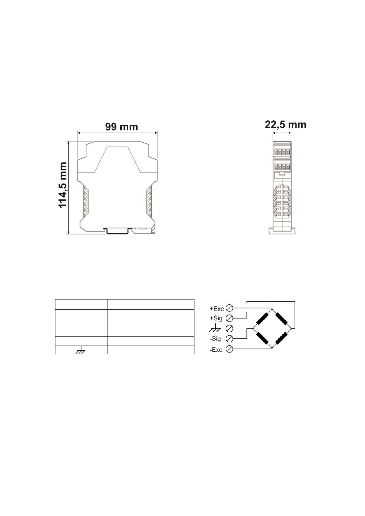
Dimensions
Front Width:22,5 mm, Front Length: 99 mm , Height:114,5mm,

FAA-26, Technical Manual, Rev. 1.2.0, December 2020 Page 7of 14
4. Installation and Commissionıng
Recommendations
Warning:Please care the following warnings for designing the control cabinet which
will increase your system reliability.
The control cabinet should be designed so that the instrument can operate safely.
The panel should be placed in clean area, not getting direct sun light if possible, with
a temperature between -10 ºC and +40 ºC, humidity not exceeding 85% non-
condensing. All external cables should be installed safely to avoid mechanical
damages.
FAA-26 instruments are very low-level signal measuring instruments. To avoid
electrical noise, FAA-26 should be separated from the equipments that produce
electrical noise. Preferable use metal cabinet against radio frequency interference
and the cabinet shall be connected to ground against the electromagnetic
disturbances. Load cell cable and analogue output cable trays must be separated
from others, if possible. If there are noise-generating equipments such as heavy load
switches, motor control equipments, inductive loads etc., please be careful against
the EMC interference in the cabinet. Connect parallel reverse diodes to the DC
inductive loads like relays, solenoids etc. to minimize voltage peaks on the DC power
lines.
All load cell and analogue output cables coming to the control cabinet shall be
shielded.
Warning:Control cabinet design and proper installation increases reliability and
performance of the instrument. Please do not forget that the instrument must be
powered off before inserting or removing any peripheral connector.
Follow the installation and commissioning described below carefully to prevent
unwanted results after installation.
FAA-26, Technical Manual, Rev. 1.2.0, December 2020 Page 8of 14
4.1 Mechanical Installation
The place where you will use/install your instrument should be clean, if possible, not
getting direct sunlight, with a temperature between -10ºC and +40ºC, 85% maximum
relative humidity non-condensing. Install the instrument on the DIN rail in the cabinet.
The instrument mechanical drawing
4.2 Load Cell Connection
The load cell wiring should be made carefully before energizing to avoid damages to
the instrument and load cells. The input resistance of the load cells that you want to
connect should be more than 85 Ω.
Pin Name
Load Cell Cable
+Ex
+ Excitation
-Ex
-Excitation
+Si
+ Signal
-Si
-Signal
Shield

FAA-26, Technical Manual, Rev. 1.2.0, December 2020 Page 9of 14
4.3 Analogue Output Connection
Only one of the analogue output types can be used at the same time and must be
selected in the setup. Install the analogue output measuring instrument for
adjustment if needed.
Pin Name
Definition
I
Current Output
V
Voltage Output
G
GND
Shield
Current output connection
Voltage output connection
4.4 Changing of the Analogue Output Type
FAA-26 checks the T and R pins connection and sets its analogue output according
to the table below at power on. To change the analogue output mode short circuit or
open circuit T and R pins of the instrument before power on the instrument.
Analogue Output Type
T and R pins
V/I LED
Current output
Open circuited
On
Voltage output
Short circuited
Flash

FAA-26, Technical Manual, Rev. 1.2.0, December 2020 Page 10 of 14
4.5 Commissioning
Survey the following steps before energizing the instrument.
•Mechanical installation, grounding, load cell connection and power supply
connection.
•The T and R pins on the instrument shall be defined the analogue output
type as seen in Chapter 4.4 at power on.
•The analogue output cabling should be done for the same analogue output
type.
•The adjustment rotary switches shall be at “0 “position at power on.
FAA-26, Technical Manual, Rev. 1.2.0, December 2020 Page 11 of 14
5. Adjustments
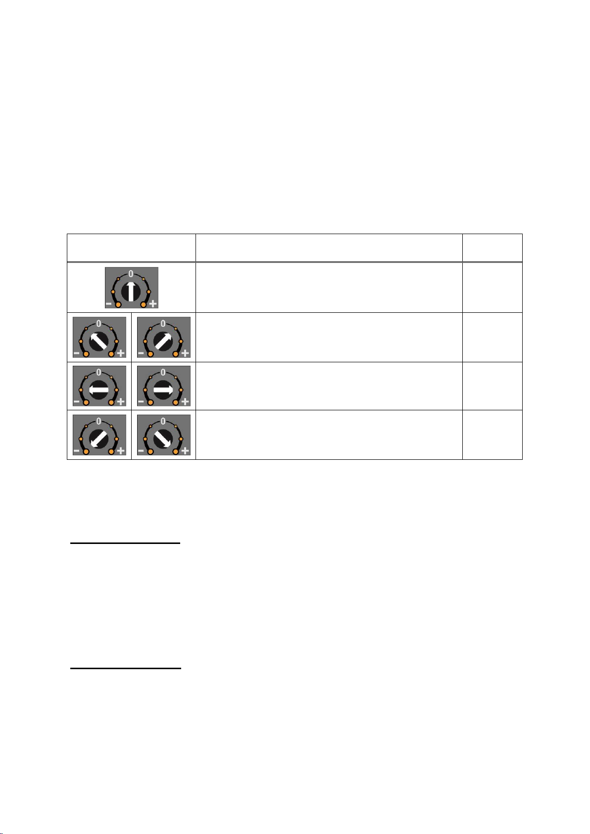
5.1 Adjustment with rotary switches
Zero and Gain adjustment rotary switches are used to adjust zero and gain of the
analogue output. Both switches must be at “0“positions when the adjustment starts.
Adjustment is done by turning the adjustment switch as described in the table below.
Adjustment rotary
switch position
Rotary switch description
Run
LED
Operation, No any change,
On
Decrease ( - ) / Increase ( + ) in slow steps
Flash
Decrease ( - ) / Increase ( + ) in medium steps
Flash
Decrease ( - ) / Increase ( + ) in big steps
Flash
RUN LED flashes to indicate the instrument is in adjustment mode.
Zero Adjustment
- Connect a measurement (e.g. multimeter) instrument to the analogue
output.
- Unload the scale.
- Increase or decrease the analogue output by zero adjustment rotary
switch.
- The zero adjustment rotary switch should be at “0“position at the end of
the adjustment.
Gain Adjustment
- Connect the measurement instrument to the analogue output.
- Load the scale.
- The analogue output value should be calculated for the applied load.

FAA-26, Technical Manual, Rev. 1.2.0, December 2020 Page 12 of 14
The analogue output value at any loading is
Analogue
Output
=
Minimum output
+
Maximum output –Minimum output
x
Load
Scale capacity
Example:
Scale capacity 100kg
Output range 4 –20 mA
Load 25kg
The 4-20mA analogue output current at 25kg is:
I out = 4mA + (( 20mA –4mA ) / 100kg ) x 25kg = 4 + 0.16 x 25 =
I out = 8 mA
The 0 –10 VDC analogue output voltage will be:
V out = 0 + (10V / 100kg ) x 25 kg = 0,1 x 25 =
V out = 2.5 VDC
- Increase or decrease the analogue output by gain adjustment rotary
switch to measure the calculated output value above.
- Please make gain adjustment rotary switch “0“position.
5.2 Adjustment at PLC
All instruments are adjusted in the production to operate in its analogue output range
between 0 mV and 10 mV load cell signal as default (only for 2mV/V load cells).
Current output default adjustment is 4 –20 mA and Voltage output default range is
0 –10 VDC .
For example if the instrument is at factory default values and programmed to operate
4 –20 mA output range, the output will be 4 mA at 0 mV load cell signal (scale
empty) and will be 20 mA at 10 mV load cell signal (max. scale capacity).
Changing the FAA-26 instrument the re-calibration is not required because of
matching instruments in production at Flintec.
5.3 Testing the Scale Performance
You should check your scale performance by testing the scale eccentricity, scale
linearity at loading up to maximum loading value, repeatability etc. before using it.
FAA-26, Technical Manual, Rev. 1.2.0, December 2020 Page 13 of 14
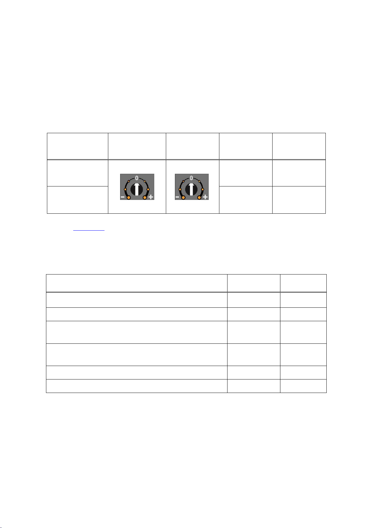
6. Operation
There are 3 LEDs and 2 adjustment rotary switches on the front panel of FAA-26.
The rotary switches should be at “0“ positions for operation.
In operation rotary switch positions, T and R pins connection, and LEDs
announces are:
Analogue
Output Type
Gain Adj.
Sw. position
Zero Adj.
Sw. position
T and R pins
V/I LED
( after power
on )
Current
Open
circuited
On
Voltage
Short
circuited
Flash
Refer to chapter 8 in case of the Err LED turns on.
The analogue output signal also gives information about the status of the system and
the weighing process to inform PLC as:
Condition
Current
output
Voltage
output
Operation
X
X
Programming
X
X
The weight is higher than the range
(Over signal to PLC)
24 mA
11 V
The weight is under than the zero range
(Under signal to PLC)
0 mA
-4.0 V
“Error” signal to PLC
0 mA
0 V
“ADC is out of operating range” error to PLC
24 mA
11 V

FAA-26, Technical Manual, Rev. 1.2.0, December 2020 Page 14 of 14
7. Trouble Shooting
The type FAA-26 amplifier was designed as a very reliable and virtually error free
instrument. However, if an error occurs, do not attempt to repair the equipment
before you understand what caused the error. Note the status of the front panel LEDs
and try to find the problem with the help of the table given below. Don’t let
unauthorized people interfere with the instrument.
FRONT PANEL LEDS
DEFINITION
Run
V/I
Err
Off
Off
Off
- No power
- Board failure
On
On
Off
- Operation in 4 –20 mA output type.
On
Flash
Off
- Operation in 0 –10 VDC output type.
On
X
On
Output type is 4 –20 mA or 0 –10 VDC
- Input signal is out of range
- Calibration needed.
- Check output circuit and cabling.
- Board failure
Flash
ON
ON
- Calibration mode
- Setting mode
The analogue output also gives additional information about the weighing system as
described in chapter 6.
Flintec GmbH
Bemannsbruch 9
74909 Meckesheim
GERMANY
www.flintec.com
Table of contents
Other Flintec Amplifier manuals


Popular Amplifier manuals by other brands


JL Audio
JL Audio XD 800/8v2 owner's manual

Artone
Artone T-206 user manual

Kenwood
Kenwood KAC-8406 instruction manual

Sony
Sony XM-2150GSX Marketing Specifications Service manual

Bosch
Bosch Plena Easy Line PLE-1P120-EU Installation and user instructions

Analog Technologies
Analog Technologies AHVA250V2X10MA quick start guide


