Flintec EA250 User manual

EA250
Analogue Amplifier
User Manual
flintec.com

Flintec EA250 User Manual ea250-e-aa-man-en-1.0.0
1
EA250 Manual
Contents
Chapter 1 Introduction to EA250 .................................................................................................... 2
The Strain Gauge Amplifier EA250..................................................................................................... 2
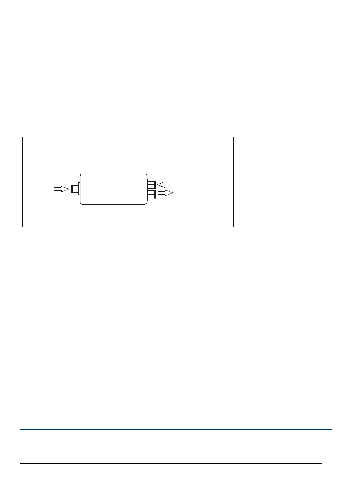
Figure 1.1 EA250 Signal Conditioner .................................................................................................. 2
Chapter 2 Installing the EA250 ....................................................................................................... 3
Pre Installation............................................................................................................................ 3
Figure 2.1 Dimensions ................................................................................................................... 3
Cabling ..................................................................................................................................... 4
Power Connection ........................................................................................................................ 4
Figure 2.2 Power Connection........................................................................................................... 4
Figure 2.3 IS1224 Module Connections................................................................................................ 4
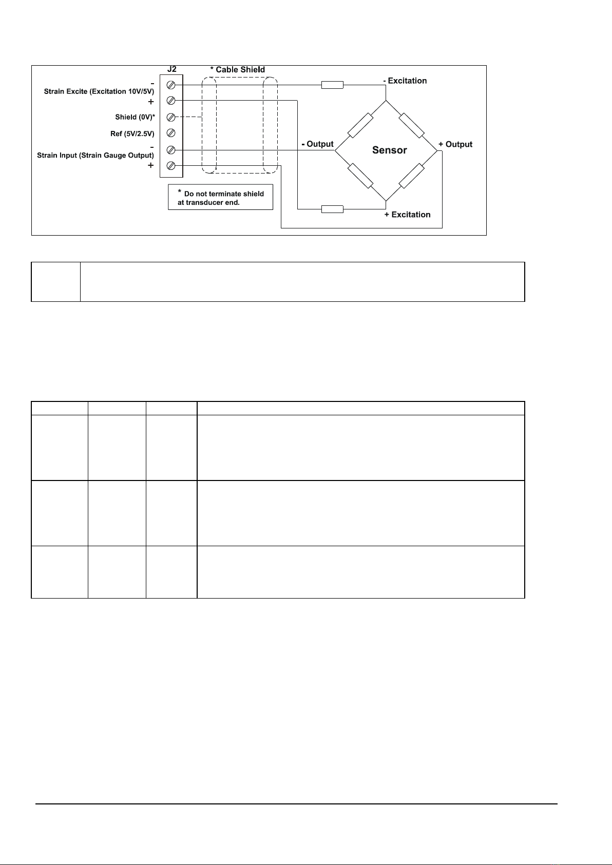
Figure 2.4 Input (Sensor) Connections ................................................................................................ 5
Table 2.1 ................................................................................................................................... 5
Output Connections ...................................................................................................................... 6
Figure 2.5 Output Connections......................................................................................................... 6
Chapter 3 Switch Settings ............................................................................................................. 7
Figure 3.1 Output Settings–Switch 4 .................................................................................................. 7
Table 3.1 Output Option ................................................................................................................ 7
Table 3.2 Switch 4........................................................................................................................ 7
Table 3.3 ................................................................................................................................... 8
Output Filter Settings –Switch 3 ....................................................................................................... 8
Table 3.4 Switch 3........................................................................................................................ 8
Table 3.5 ................................................................................................................................... 9
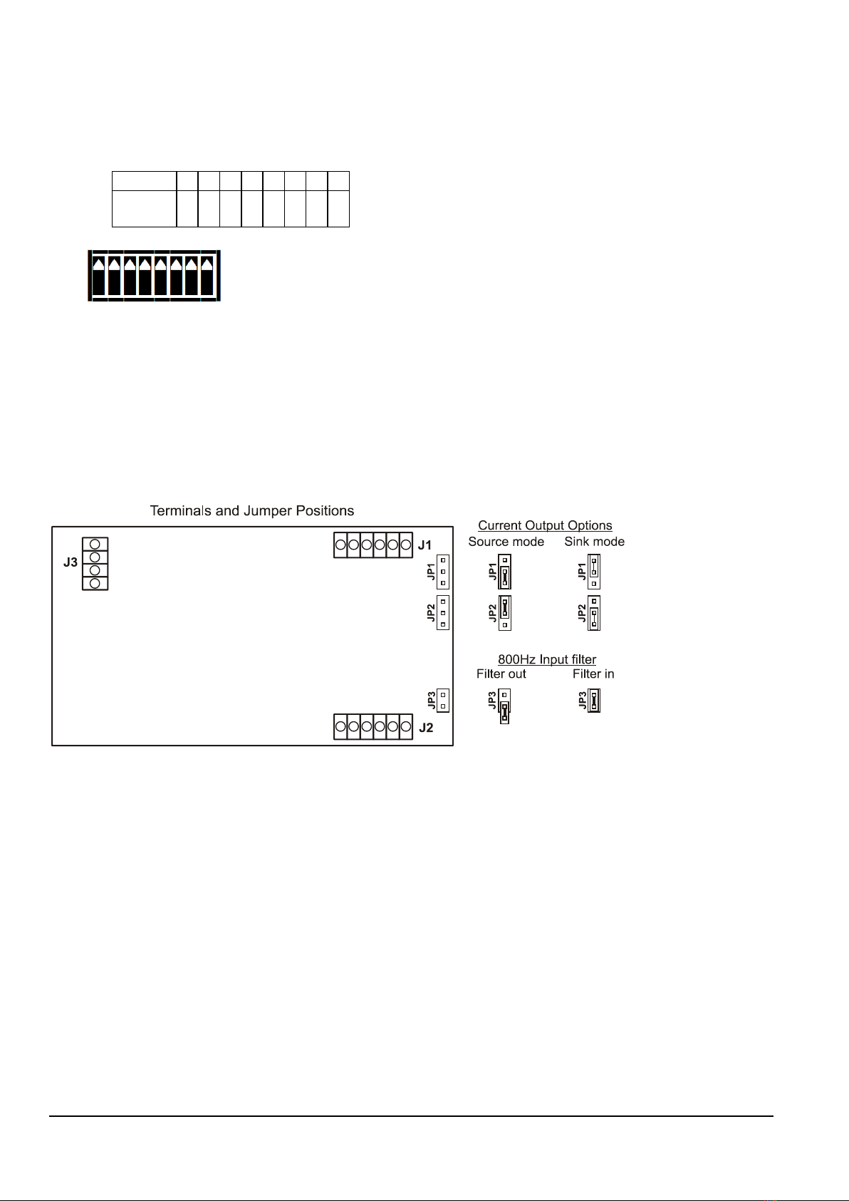
Output Current Mode and Input Filter Settings – Jumpers JP1, JP2 & JP3 ..................................................... 9
Figure 3.2 .................................................................................................................................. 9
Span (Gain) Setting Switch SW1....................................................................................................... 10
Table 3.6 – SW1 .......................................................................................................................... 10
Table 3.7 .................................................................................................................................. 11
Shunt Calibration Switch SW1/8 ...................................................................................................... 11
Table 3.8 .................................................................................................................................. 11
Figure 3.3 ................................................................................................................................. 11
Zero (Offset) Setting Switch SW2 ..................................................................................................... 12
Table 3.9 .................................................................................................................................. 12
Table 3.10 ................................................................................................................................ 12
Chapter 4 Calibration.................................................................................................................. 13
Output ..................................................................................................................................... 13
Zero Offset ............................................................................................................................... 13
Sensitivity................................................................................................................................. 13
Figure 4.1 Calibration Connections Using a Millivolt Source ..................................................................... 15
Chapter 5 The EA250BCM Bridge Completion Module.......................................................................... 16
Half Bridge................................................................................................................................ 16
Quarter Bridge ........................................................................................................................... 16
Shunt Calibration ........................................................................................................................ 17
Remote Shunt Calibration.............................................................................................................. 18
Chapter 6 Troubleshooting ........................................................................................................... 19
Chapter 7 Product Care ............................................................................................................... 21
Chapter 8 Glossary ..................................................................................................................... 22
Chapter 9 Specifications for EA250 Load Cell Amplifiers...................................................................... 25
CE Approvals.............................................................................................................................. 26
Warranty .................................................................................................................................. 26
Figure 9.1 Connection Details ......................................................................................................... 27

Flintec EA250 User Manual ea250-e-aa-man-en-1.0.0
2
Chapter 1 Introduction to EA250
The Strain Gauge Amplifier EA250
The EA250 is a Strain Gauge Amplifier, converting a strain gauge input to a voltage or current output – otherwise
known as a Signal Conditioner.
The EA250 provides a wide range of signal conditioning for Strain Gauges, Load Cells, Pressure and Torque
transducers.
Figure 1.1 EA250 Signal Conditioner
POWER
SUPPLY
STRAIN
GAUGE
AMPLIFIER
OUTPUT
±10V
±5V
0-5V
0-20mA
4-20mA
Inputs
Load Cells
Strain Gauges
Torque Transducers
Pressure Transducers
110/230 V AC
18-24V DC
INPUT
Offered in two versions, the EA250/AC for 110/230V AC or 18-24V DC operation and the EA250/DC which is DC
powered only.
A further powering option is available; the IS1224 module comprises a DC-DC converter enabling the EA250 to be
powered from 9-36V DC. See Figure2.3 for details.
The ISS1224 can only be fitted to the EA250/DC as it occupies the same space as the mains transformer in the
EA250/AC. The EA250/AC however, is isolated when AC powered by virtue of its mains transformer.
Transducer SENSITIVITY of between 0.1mV/V and 30mV/V are possible.
This is achieved by a combination of gain (span) DIP switches and associated fine adjustment by a potentiometer.
Similarly, transducer zero OFFSET and SCALE DEAD BAND of up to 79% can be compensated for in the module.
This is achieved again by a combination of zero DIP switches and associated fine adjustment by a potentiometer.
The module has built-in FILTERS to cancel the field effects of vibration, agitation and electrically noisy
environment.
The on-board low pass filter can be switched in and adjusted (from 1Hz to 5kHz) using a series of DIP switches.
A wide range of proportional output options for currents and voltages can be configured by DIP switch settings.
Both the AC and DC versions are based on a common board and are mounted in an IP65 (NEMA 4X) ABS case.
The EA250 is a single channel signal conditioner but can supply sufficient excitation current to supply four 350 Ohm
load cells connected in parallel. The resulting output is the average of the individual cells.
An optional EA250BCM bridge completion module is available to facilitate connecting half and quarter bridges to
the EA250 – see Chapter 5 for details.

Flintec EA250 User Manual ea250-e-aa-man-en-1.0.0
3
Chapter 2 Installing the EA250
Pre Installation
See Specification details in Chapter 10 for details of Environmental Approvals.
Carefully remove the EA250/AC unit from its packing. Check that the unit is complete and undamaged.
The EA250 units can operated in any industrial environment providing the following limits are not exceeded
Operating Temperature
-10 ºC to +50 ºC
Humidity
95% non condensing
Storage temperature
-20 ºC to +70 ºC
While the unit is sealed to IP65 (NEMA 4X) it is advisable to follow the following installation practice where possible
•Minimise vibration.
•Do not mount next to strong electrical fields (transformers, power cables)
•Ensure easy access to interior of the module
•Install a 500mA Quick-blow fuse, as the unit is not internally fused.
•Always ensure the lid is properly fitted and all 4 screws tightened.
•Always ensure the cable gland is sealing against the cable to maintain the IP (NEMA) rating.
Figure 2.1 Dimensions
The 4 screws for the lid are captive and must be tightened to maintain the seal.
The 4.5mm (0.18”) holes for the mounting screws in the base are directly behind the screws for the lid.
The box must not be drilled as this would invalidate the IP rating
Allow sufficient space at both sides for the cable entry.
The Nylon 66 M16 cable glands are designed for ROUND cables.
The waterproof entry and strain relief will seal to a higher rating than the enclosure.
Cable diameter should be between 4mm (0.16”) and 7mm (0.27”)

Flintec EA250 User Manual ea250-e-aa-man-en-1.0.0
4
Cabling
Power Connection
Two power supply options are available
EA250/AC:
220/230VAC, 50/60Hz
110/120VAC, 50/60Hz
5W Max.
EA250/DC:
18-24V DC, 5W (approx. 150mA fully loaded)
NOTE: The EA250/AC can be powered from AC or DC sources whichever is available.
It is also possible to connect BOTH AC and DC simultaneously for security of power
supply.
Figure 2.2 Power Connection
Standard mains 2 or 3 core cable PVC sheathed (unshielded) cable will suffice for the power.
NOTE:
Connect the appropriate power to the EA250. For AC powering observe the correct
transformer jumper connections as shown in Figure 2.2 above.
(This diagram is also provided inside the lid).
Figure 2.3 IS1224 Module Connections
To accommodate automotive installations, the EA250 can be fitted with an IS1224 module enabling it to be powered
from 9 to 36V DC.
This module also has the advantage of electrically isolating the DC power supply from the measurement electronics
which minimises errors and instability due to earth loops in the system.
J1
J2
9-36V
DC
IS1224 Module
+
-
The power supply should be capable of supplying at least 1A for 12V installations and 0.5A for 24V.
Connections to the EA250 input/output signal and the power supply are made via 2.5mm² field terminal connectors.
Cable entry in the cased versions is via glands in the ends of the case.
220-230 V AC
J 3
N
110 - 120 V AC
N
L L
J 3
18 -24 V DC
J 1
+-

Flintec EA250 User Manual ea250-e-aa-man-en-1.0.0
5
Figure 2.4 Input (Sensor) Connections
NOTE:
Strain Excite is the Excitation to the transducer.
Strain Input is the Signal from the transducer.
The Ref 5V/2.5V is generated internally and used for calibration
The cable connecting the sensor to the EA250 should be shielded.
This typical cable data is provided for information only.
The cable should have 2 x twin twisted cables. Ideally with each pair individually shielded and with an overall
shield.
Table 2.1
Country
Supplier
Part No
Description
UK
Farnell
148-539
Individually shielded twisted multipair cable (7/0.25mm)- 2 pair
Tinned copper drain. Individually shielded in polyester tape.
Diameter: 4.19 mm
Impedance: 54 Ohms: Capacitance/m: core to core 115 pF & core to
shield 203 pF
UK
Farnell
585-646
Individually shielded twisted multipair cable (7/0.25mm)- 3 pair
Tinned copper drain. Individually shielded in polyester tape.
Diameter: 6.86 mm
Impedance: 62 Ohms: Capacitance/m: core to core 98 pF & core to
shield 180 pF
UK
RS
367-533
Braided shielded twisted multipair cable (7/0.2mm)- 1 pair
Miniature- twin -round Diameter: 4.8 mm
Impedance: 62 Ohms: Capacitance/m: core to core 120 pF & core to
shield 210 pF
If possible segregate the signal cable from Power Cables; allow a 1 metre (3 feet) distance from such cables.
Do not run signal cables parallel to power cables. Cross such cables at right angles.
The ground connection conductor should have sufficient cross-sectional area to ensure a low impedance path to
attenuate RF interference.

Flintec EA250 User Manual ea250-e-aa-man-en-1.0.0
6
Output Connections
Two analogue outputs are available from the EA250, proportional DC current and DC voltage.
The ranges available are as follows: -
Output
Range
DC voltage
±10V
±5V
NB:
Maximum Load on voltage ranges is 2mA.
0 - 10V
0 - 5V
DC current
0 - 20mA
NB:
Maximum impedance 500R.
4 - 20mA
The DC current support both ‘sink’ and ‘source’ modes of operation.
Two jumpers JP1 & JP2 provide the means of selecting the desired mode.
Figure 2.5 Output Connections
In ‘Sink’ mode the positive end of the load is connected to the internal +15V supply on the EA250 and the negative
end is connected to the EA250 output. The current through the load is ‘sunk’ by the EA250 towards ground (0V).
N.B. In this mode neither connection to the output load is electrically common to the load cell.
Select this option by fitting the two jumpers, JP1 and JP2 to the ‘outside’ positions (See Figure 3.2)
In ‘Source’ mode the positive end of the load is connected to the EA250 output and the current is ‘sourced’ by the
EA250 output through the load towards ground (0V).
This mode has the advantage that the negative output connection is common to the load cell ‘- Excitation’
terminal.
Select this option by fitting the two jumpers, JP1 and JP2 to the ‘inside’ positions (See Figure 3.2)
See Chapter 3 for switch settings and details of SINK & SOURCE jumpers.

Flintec EA250 User Manual ea250-e-aa-man-en-1.0.0
7
Chapter 3 Switch Settings
Switch Positions
e.g. the switches in Figure 3.1 are depicted as ALL ON.
Figure 3.1 Output Settings–Switch 4
Use switch 4 to select the required output and, if
required, the low pass filter and 5V Excitation.
(See Tables 3.1 and 3.2)
Table 3.1 Output Option
Input Range
4-20mA
0 - 20mA
4-20mA
0 - 20mA
0 - 10V
0 - 5V
±10V
±5V
+ Full Scale
20mA
20mA
20mA
20mA
10V
5V
10V
5V
↑
↑
↑
↑
↑
↑
↑
↑
↑
0
4mA
0mA
12mA
10mA
5V
2.5V
0V
0V
↓
↓
↓
↓
↓
↓
↓
- Full Scale
n/a
n/a
4mA Note 1
0mA Note 1
0V
0V
-10V
-5V
N.B. Full scale output on the voltage ranges is achieved with a bi-polar (±) input
Note 1 Negative inputs can be accommodated on the current (mA) output ranges by setting the ‘Zero’ switch SW2
to +50% (Table 3.8) and setting SW1 to twice the required mV/V setting (Table 3.6).
Table 3.2 Switch 4
Analogue Output and Excitation Voltage Options - SW4
SW4
1
2
3
4
5
6
7
8
±10V
0↓
0↓
0↓
X
X
1↑=Filter in
1↑Filter out
1↑=10V Exc 0↓=5V Exc
±5V
0↓
1↑
0↓
X
X
1↑=Filter in
1↑Filter out
1↑=10V Exc 0↓=5V Exc
0-10V
0↓
1↑
1↑
X
X
1↑=Filter in
1↑Filter out
1↑=10V Exc 0↓=5V Exc
0-5V
1↑
1↑
1↑
X
X
1↑=Filter in
1↑Filter out
1↑=10V Exc 0↓=5V Exc
0-20mA
X
X
X
0↓
0↓
1↑=Filter in
1↑Filter out
1↑=10V Exc 0↓=5V Exc
4-20mA
X
X
X
1↑
1↑
1↑=Filter in
1↑Filter out
1↑=10V Exc 0↓=5V Exc
Filter out
X
X
X
X
X
0↓
1↑
1↑=10V Exc 0↓=5V Exc
Filter in
X
X
X
X
X
1↑
0↓
1↑=10V Exc 0↓=5V Exc
10V Exc
X
X
X
X
X
1↑=Filter in
1↑Filter out
1↑
5V Exc
X
X
X
X
X
1↑=Filter in
1↑Filter out
0↓
Switch settings (0 = Off 1 = On X = Don’t Care)
Important:
Low pass filtering is switched into operation by setting SW4/6 ‘ON’↑and SW4/7 ‘OFF’↓.
Reverse these settings to bypass the filter.
It should be noted that either one of these switches MUST be on but not BOTH
Output Option

Flintec EA250 User Manual ea250-e-aa-man-en-1.0.0
8
Example: - 0-10 Volt output with no filter required.
Table 3.3
SW4
1
2
3
4
5
6
7
8
0-10V
0
↓
1
↑
1
↑
X
X
0
↓
1
↑
X
SW4
Output Filter Settings –Switch 3
The EA250 incorporates a second order (-12dB/oct) low pass filter which can be switched in to improve the
performance and output signal quality in electrically noisy environments.
It can also be used to reduce the effects of high frequency fluctuations in the load or applied force to the load cell.
The cut off frequency of the filter is set by the DIP switch SW3 as illustrated in the table below
Table 3.4 Switch 3
SW3
1
2
3
4
5
6
7
8
1Hz
0
↓
0
↓
0
↓
0
↓
0
↓
0
↓
1
↑
1
↑
5Hz
1
↑
0
↓
0
↓
0
↓
0
↓
1
↑
1
↑
1
↑
10Hz 1
↑
1
↑
0
↓
0
↓
1
↑
1
↑
1
↑
1
↑
50Hz
1
↑
1
↑
1
↑
1
↑
1
↑
1
↑
1
↑
1
↑
100Hz
0
↓
0
↓
0
↓
0
↓
0
↓
0
↓
0
↓
0
↓
500Hz
1
↑
0
↓
0
↓
0
↓
0
↓
1
↑
0
↓
0
↓
800Hz
see note**
1kHz
1
↑
1
↑
0
↓
0
↓
1
↑
1
↑
0
↓
0
↓
5kHz
1
↑
1
↑
1
↑
1
↑
1
↑
1
↑
0
↓
0
↓
** Note:
A SECONDARY low pass filter, with a cut off frequency of 800Hz, can be switched into the EA250 input by fitting a
link to JP3 (see Figure 3.2)
Important:
Low pass filtering is switched into operation by setting SW4/6 ‘ON’↑and SW4/7
‘OFF’↓. Reverse these settings to bypass the filter.
It should be noted that either one of these switches MUST be on but not BOTH

Flintec EA250 User Manual ea250-e-aa-man-en-1.0.0
9
Example:-
The Switch Settings for a cut-off frequency of 50 Hz setting is illustrated below.
Note: SW4/6 must be ‘ON’ and SW4/7 must be ‘OFF’.
Table 3.5
SW3
1
2
3
4
5
6
7
8
50Hz 1
↑
1
↑
1
↑
1
↑
1
↑
1
↑
1
↑
1
↑
SW3
Output Current Mode and Input Filter Settings – Jumpers JP1, JP2 & JP3
Figure 3.2
Refer to Figure 2.5 for details of wiring connections to J1.

Flintec EA250 User Manual ea250-e-aa-man-en-1.0.0
10
Span (Gain) Setting Switch SW1
Ranges 1 to 60 – from 0.06 mV/V to 30.30 mV/V
↑= ON (1) ↓= OFF (0). SW1/8 switches on the shunt cal function – see Table 3.8
Table 3.6 – SW1
27.10 mV/V
57
1 2 3 4 5 6 7 8
x
28.30 mV/V
23.10 mV/V
15.60 mV/V
5.72 mV/V
4.89 mV/V
4.05 mV/V
3.72 mV/V
2.95 mV/V
2.35 mV/V
1.49 mV/V
0.80 mV/V
0.65 mV/V
0.50 mV/V
0.31 mV/V
0.11 mV/V
29.30 mV/V
24.60 mV/V
17.80 mV/V
7.50 mV/V
5.12 mV/V
4.26 mV/V
3.73 mV/V
3.19 mV/V
2.49 mV/V
1.78 mV/V
0.91 mV/V
0.70 mV/V
0.55 mV/V
0.34 mV/V
0.17 mV/V
30.30 mV/V
25.90 mV/V
19.70 mV/V
10.50 mV/V
5.34 mV/V
4.36 mV/V
4.00 mV/V
3.35 mV/V
2.63 mV/V
1.99 mV/V
1.20 mV/V
0.75 mV/V
0.60 mV/V
0.39 mV/V
0.23 mV/V
58
54
50
46
42
38
34
30
26
22
18
14
10
6
2
59
55
51
47
43
39
35
31
27
23
19
15
11
7
3
60
56
52
48
44
40
36
32
28
24
20
16
12
8
4
1
1
1
1
1
1
1
1
1
1
1
1
1
1
1
1
1
1
1
1
1
1
1
1
1
1
1
1
1
1
1
1
1
1
1
1
1
1
1
1
1
1
1
1
1
2
2
2
2
2
2
2
2
2
2
2
2
2
2
2
2
2
2
2
2
2
2
2
2
2
2
2
2
2
2
2
2
2
2
2
2
2
2
2
2
2
2
2
2
2
3
3
3
3
3
3
3
3
3
3
3
3
3
3
3
3
3
3
3
3
3
3
3
3
3
3
3
3
3
3
3
3
3
3
3
3
3
3
3
3
3
3
3
3
3
4
4
4
4
4
4
4
4
4
4
4
4
4
4
4
4
4
4
4
4
4
4
4
4
4
4
4
4
4
4
4
4
4
4
4
4
4
4
4
4
4
4
4
4
4
5
5
5
5
5
5
5
5
5
5
5
5
5
5
5
5
5
5
5
5
5
5
5
5
5
5
5
5
5
5
5
5
5
5
5
5
5
5
5
5
5
5
5
5
5
6
6
6
6
6
6
6
6
6
6
6
6
6
6
6
6
6
6
6
6
6
6
6
6
6
6
6
6
6
6
6
6
6
6
6
6
6
6
6
6
6
6
6
6
6
7
7
7
7
7
7
7
7
7
7
7
7
7
7
7
7
7
7
7
7
7
7
7
7
7
7
7
7
7
7
7
7
7
7
7
7
7
7
7
7
7
7
7
7
7
8
8
8
8
8
8
8
8
8
8
8
8
8
8
8
8
8
8
8
8
8
8
8
8
8
8
8
8
8
8
8
8
8
8
8
8
8
8
8
8
8
8
8
8
8
x
x
x
x
x
x
x
x
x
x
x
x
x
x
x
x
x
x
x
x
x
x
x
x
x
x
x
x
x
x
x
x
x
x
x
x
x
x
x
x
x
x
x
x
x
21.50 mV/V
53
1 2 3 4 5 6 7 8
x
49
45
41
37
33
29
25
21
17
13
9
5
1
13.20 mV/V
5.54 mV/V
4.63 mV/V
4.00 mV/V
3.46 mV/V
2.91 mV/V
2.07 mV/V
1.41 mV/V
0.75 mV/V
0.61 mV/V
0.44 mV/V
0.28 mV/V
0.06 mV/V
1
1
1
1
1
1
1
1
1
1
1
1
1
2
2
2
2
2
2
2
2
2
2
2
2
2
3
3
3
3
3
3
3
3
3
3
3
3
3
4
4
4
4
4
4
4
4
4
4
4
4
4
5
5
5
5
5
5
5
5
5
5
5
5
5
6
6
6
6
6
6
6
6
6
6
6
6
6
7
7
7
7
7
7
7
7
7
7
7
7
7
8
8
8
8
8
8
8
8
8
8
8
8
8
x
x
x
x
x
x
x
x
x
x
x
x
x
Please Note:
When using 5V Excitation (SW4 switch 8 = OFF), divide the transducer's mV/V output by two and set SW1 to the
nearest setting shown in table 3.6 above
e.g. for 2.5mV/V with 5V excitation choose the 1.2mV/V setting

Flintec EA250 User Manual ea250-e-aa-man-en-1.0.0
11
Example:-
A strain gauge has a sensitivity of 2.809 mV /V - Select Switch Setting number 28 from Table 3.6 and fine tune with
potentiometer PI
Table 3.7
SW1
1
2
3
4
5
6
7
8
2.63 mV/V
0
↓
1
↑
1
↑
0
↓
0
↓
0
↓
0
↓
X
SW1
Refer to Chapter 4 for calibration details.
Shunt Calibration Switch SW1/8
SW1/8 connects a 120k 50ppm surface mount resistor across the ‘+Excitation’ and ‘+ Input’ terminals of the EA250.
This shunts one arm of the connected load cell to produce a known change in output which can be used for
calibration or checking the integrity of the load cell and associated wiring.
Table 3.8
SW1
1
2
3
4
5
6
7
8
Shunt Cal ON
x
x
x
x
x
x
x
1
↑
Shunt Cal OFF
x
x
x
x
x
x
x
0
↓
WARNING: Do not activate the shunt calibration switch without a load cell connected as this may damage the
EA250!
The 120k resistor can be taken out of circuit and replaced by a user defined leaded component by carefully cutting
the fine link as shown in Figure 3.3. Use the right hand pad and either of the left hand pads to fit the new
component.
The surface mount resistor can be reinstated by re-connecting the two pads either side of the cut link.
Figure 3.3

Flintec EA250 User Manual ea250-e-aa-man-en-1.0.0
12
Zero (Offset) Setting Switch SW2
This offset can be used to compensate for the transducer zero error, to tare the scale dead load or to shift the
output.
These settings allow the user to calibrate a zero offset. The range allows for up to 79% of the span.
Potentiometer P2 provides fine adjustment.
Table 3.9
SW2
1
2
3
4
5
6
7
8
%
+ ve Offset
- ve Offset
40%
20%
10%
5%
2%
1%
Example:-
An installation has a tare of 15 kg with a 200kg strain gauge which gives an output of 6.37mV/V at 10V excitation.
The tare equates to 7.5% (15/200). Set the switches to nearest % (5 + 2) and fine trim with Potentiometer P2.
The tare must be subtracted therefore the ‘- ve Offset’ switch SW2/2 should be ‘ON’.
The calibrated zero mV reading would be 4.78 mV i.e. 7.5% of 63.7mV
Table 3.10
SW2
1
2
3
4
5
6
7
8
7.5%
0
↓
1
↑
0
↓
0
↓
0
↓
1
↑
1
↑
0
↓
SW2
Note
SW2 /1 & 2 should never be 'ON ' together. Either one or other should be 'ON ' if an
offset is required; otherwise both switches should be 'OFF '.
Switch settings 3 to 8 are ADDITIVE. The offset value of each switch is added to give
a total offset of 78%.
Fine adjustment is provided by potentiometer P2.

Flintec EA250 User Manual ea250-e-aa-man-en-1.0.0
13
Chapter 4 Calibration
The EA250 provides the excitation supply and signal conditioning to cater for a wide range of strain gauges, load
cells, pressure transducers or torque transducers.
Output
Select the analogue output range as detailed in Chapter 3, Figure 3.1, Tables 3.1 & 3.2 by means of SW4.
Zero Offset
Select the offset as detailed in Chapter 3, Table 3.9 by means of SW2.
Having selected the polarity and the offset nearest to that required with the switches use the fine potentiometer P2
to achieve the final setting.
Sensitivity
Select the sensitivity as detailed in Chapter 3, Table 3.6 by means of SW1.
Switches 1-4 of SW1 provide fine setting of the EA250 sensitivity while switches 5-7 give coarse control.
This arrangement allows the EA250 to cover a wide range of strain gauge sensitivities without sacrificing stability
and ease of set up.
Locate the required sensitivity in the table and set switches 1-7 of SW1 accordingly.
Potentiometer P1 provides fine trimming and range overlap to enable the EA250 to be calibrated precisely to any
given value within its ranges.
Note 1
If the range is repeated in the table e.g. 4mV/V (4.0, 4.05 and 4.0 mV/V) choose the
setting which has the greatest number of switches 1-4 set to ‘off’ i.e. SW1 =[1000]
[000]. This will enable finer trimming to the final value using potentiometer PI.
The sensitivity settings shown in Table 3.6 assume that the load cell is fully loaded. The sensitivity settings can be
used to maximise the output when the full range of the load cell is not being used. Here are a couple of examples.
Example 1
A 2.5mV/V load cell provides 10V for an l00Ib load. However it is never loaded above
50lb
The sensitivity setting can be set to 1.25 mV/V.
Table 3.6/20 (1.20mV/VSW1 =[1101][000]
Example
2
When
a
reduced
output
is
required
from
a
fully
loaded
transducer,
use
a
less
sensitive switch setting.
For an 8 volt output from a fully loaded 2.5mV/V load cell use the 3.19mV/V setting
i.e. (10/8x2.5=3.125mV/V)
Table 3.6 /31 (3.19mV/V SW1 =[0010][000]

Flintec EA250 User Manual ea250-e-aa-man-en-1.0.0
14
The EA250 can be calibrated with the transducer connected, provided that two calibration points can be
implemented, e.g. by applying known weights or forces. If this is not possible, a stable mV source or load cell
simulator can be used provided that the precise sensitivity (mV/V) and full range output (kg) of the transducer is
known. In this case the 'Ref (5V/2.5V)' output should be connected to 'Strain Input-' and the mV source applied
between ‘Strain Input+’ and ‘Strain Input-’.
Actual calibration is carried out in the following way:-
1. Set the correct switch settings on SW1 as described above using the transducer's calibration sheet supplied by
the manufacturer. This is normally specified as sensitivity or full range output and should be in mV/V
2. Apply the known low calibration conditions (weight, force or mV/V: this may be zero if required), and note the
analogue output, having ensured that the SW1 settings are correct for the transducer sensitivity as step 1 above.
3. Apply the known high calibration conditions (for optimum accuracy this should be at least 75% of full load) and
note the analogue output.
4. Use the fine trim control, P1, to obtain the required change in Volts or mA, between the two calibration points
(steps 2 and 3) e.g. If the required output at the low calibration point is 0V and the required output at the high
calibration point is 7.5V, adjust P1 in step 4 to produce a change of 7.5V between the calibration points.
Initially, the low calibration point may not produce 0V at the output. If this is the case, note the reading, e.g.
0.5V, apply the high calibration conditions and trim P1 for the required change in output i.e. trim the output for
0.5 + 7.5 = 8V.
5. Use the fine ‘Zero’ control, P2 in conjunction with the coarse switches SW2/3-8 and polarity switches SW2/1 and
2 to set the output to the required absolute values. Each switch within SW2 offsets the output by a particular
percentage of full scale as shown in Table 3.9
N.B. It may be necessary to repeat these steps until the required output is achieved.

Flintec EA250 User Manual ea250-e-aa-man-en-1.0.0
15
Figure 4.1 Calibration Connections Using a Millivolt Source
mV Source
-+
J2
Strain Input (Strain Gauge Output)
Ref (5V/2.5V)
Shield (0V)
Strain Excite ( 10V/5V)Excitation
-
+
-
+
1. The ‘Ref (5V/2.5V)’ should be connected to ‘Strain Input-’ and the mV source applied between ‘Strain Input+’ &
‘Strain Input-’
2. Set the correct switch settings on SW1 as described above using the transducer's calibration sheet supplied by
the manufacturer. This is normally specified as sensitivity or full range output and should be in mV/V
3. Ensure the Zero and Span switch settings are correct, as detailed in Chapter 3, Tables 3.6 & 3.9
4. Apply the known low calibration conditions and fine adjust P2.
5. Apply the known high calibration conditions and fine adjust P1
6. Repeat steps 3 and 4 until the required output is achieved.
Hint
If the required output at the low calibration point is 0V and the required output at
the high calibration point is 7.5V, adjust P1 in step 5to produce achange of 7.5V
between the calibration points. Initially, the low calibration point may not produce 0V
at the output. If this is the case, note the reading, e.g. 0.5V, apply the high
calibration conditions and trim P1 for the required change in output, i.e. Trim the
output for 0.5 +7.5 =8V.

Flintec EA250 User Manual ea250-e-aa-man-en-1.0.0
16
Chapter 5 The EA250BCM Bridge Completion Module
The EA250BCM is a retro-fit PCB which facilitates connecting a half or quarter-bridge strain gauge to the EA250.
Screw terminal connections accept a wide range of bridge completion resistor types and enable on-site installation
without soldering equipment.
Two high stability resistors (±5ppm/°C) are fitted to the EA250BCM to form the ‘fixed’ arms of the bridge while the
user’s half or quarter-bridge strain gauge elements complete the circuit. In the latter case a ‘bridge completion’
resistor is required to form the full ‘Wheatstone bridge’ topology.
Half Bridge
The half-bridge is simply connected to the EA250 via the screw terminals as shown below and no additional
components are required:
S+ D Ref Shld +EXC -EXC
R Tension R Comp R S/Cal
Rm S/C 24V
Loc Rem
- + Off
S/Cal
Quarter Bridge
The quarter-bridge, together with its completion resistor can be wired in two ways depending on whether the user
requires a positive output as a result of the strain gauge being subjected to a compression force or a tension
(stretching) force.
S+ D Ref Shld +EXC -EXC
R Tension R Comp R S/Cal
Rm S/C 24V
Loc Rem
- + Off
S/Cal
3-Wire Quarter Bridge - compression gives +ve output
Bridge completion
resistor
Rwire
Sense
Rwire
3-wire connection compensates for the resistance of the cable cores.

Flintec EA250 User Manual ea250-e-aa-man-en-1.0.0
17
3-Wire Quarter Bridge - tension gives positive output
S+ D Ref Shld +EXC -EXC
R Tension R Comp R S/Cal
Rm S/C 24V
Loc Rem
- + Off
S/Cal
Bridge completion
resistor
Sense
Rwire
Rwire
Shunt Calibration
An additional feature of the EA250BCM allows the user to perform a ‘Shunt Calibration’ (shunt cal) test to check the
integrity of the strain gauge(s), wiring and EA250 calibration.
This involves temporarily connecting a relatively high value resistor between the positive output of the bridge to
either the positive or negative excitation connections.
Screw terminals are provided for the resistor which should be scaled appropriately taking into account the strain
gauge impedance.
The resulting change in output when the shunt cal resistor is connected should be recorded and referred to when
future checks are performed. Any deviation outside tolerance limits will flag up a fault condition.
To implement the ‘shunt cal’ operation on the EA250BCM a set of header pins are provided with a shorting link that
can be fitted in one of three positions: ‘Off’, ‘+’ (positive shift) and ‘–‘ (negative shift). These are clearly marked
on the PCB.
The shorting link should be parked in the ‘Off’ position for normal use.
S+ D Ref Shld +EXC -EXC
R Tension R Comp R S/Cal
Rm S/C 24V
Loc Rem
- + Off
S/Cal
Local positive shunt calibration
Shunt calibration
resistor

Flintec EA250 User Manual ea250-e-aa-man-en-1.0.0
18
S+ D Ref Shld +EXC -EXC
R Tension R Comp R S/Cal
Rm S/C 24V
Loc Rem
- + Off
S/Cal
Local negative shunt calibration
Shunt calibration
resistor
Remote Shunt Calibration
In addition, ‘Remote Shunt Cal’ can be performed by means of a N.O. 24V DC relay fitted to the module. The relay
supply can be situated some distance from the EA250 and even be connected in parallel to several EA250s in a
multiple installation enabling them to be shunt cal’d simultaneously.
S+ D Ref Shld +EXC -EXC
R Tension R Comp R S/Cal
Rm S/C 24V
Loc Rem
- + Off
S/Cal
Remote positive shunt calibration
24V DC
Shunt calibration
resistor
The EA250BCM can be supplied when ordering an EA250/AC or D or ordered separately for retro-fitting to existing
EA250s.
The EA250BCM is compatible with all variants of the EA250 i.e. EA250/AC, EA250/DC and EA250s fitted with the
IS1224 isolated DC power supply module.

Flintec EA250 User Manual ea250-e-aa-man-en-1.0.0
19
Chapter 6 Troubleshooting
1. No output
a) Check power supply is present (LED is on).
b) Check the output connections are correct.
c) Check terminations (ensure insulation is not trapped in terminal, cable break etc.)
d) Check the sensor is connected (typically reading 350 Ohm across Strain Excite + and – and also
Strain Input + and – of J2) with the power off.
e) Check the Excitation voltage (J2) is at 10V DC
1.a For voltage output
a) Check V out+ and V out- terminals are wired
b) Check the load is connected and is not open or short circuited
c) Check SW4 settings are correct for Voltage Output see Chapter 3, Table 3.2
d) Check Span and Zero settings (SW1 and SW2)
1.b For current output
a) Check Isink+ and Isink- terminals are used for 'Sink' current output
b) Check Isource+ and Isource- terminals are used for 'Source' current output.
c) Check the load is connected and is not open circuit
d) Check load does not exceed 500 Ohms.
e) In 'Sink' mode check 15 V is present at +ve terminal of load.
f) In 'Source' mode check the -ve terminal of the load is connected to ground.
g) In 'Sink' mode check the load is isolated from the load cell (sensor) excitation.
h) In 'Source' mode check the -ve output is common to the -ve Excitation.
i) Check output SW 4 settings are correct for current see Chapter 3, Table 3.2
j) Check Span and Zero settings (SW1 and SW2) see Chapter 3, Table 3.6 & 3.9
2. Low Output
This is when an output is present but not of sufficient magnitude to meet the required value.
b) Check power supply is within specified limits (i.e. is not low)
c) Check the sensor is connected (typically reading 350 Ohm across Strain Excite + and – and also
Strain Input + and – of J2) with the power off.
d) Check the Excitation voltage (J2) is at 10V DC
e) Check the calibration. Incorrect setting of the calibration Span switches are the most common cause of low
output - particularly when associated with ± Voltage outputs. Refer to the calibration instructions in Chapter 4.
Refer to tutorial on the calibration set-up.
f) Check the Zero (offset) is correct for the sensor. This too is a common reason for low outputs.
3. High output
This is when an output is present but higher (in span or zero) than required.
b) Check the sensor is connected (typically reading 350 Ohm across Strain Excite + and – and also
Strain Input + and – of J2) with the power off.
c) Check the Excitation voltage (J2) is at 10V DC
d) Check the Zero (offset) is correct for the sensor. This is a common reason for high outputs where the offset is
either omitted or incorrect for the sensor. Refer to the calibration instructions in Chapter 4
e) Refer to tutorial on the calibration set-up
f) Check the calibration. Incorrect setting of the calibration span switches is the most common cause of high
output - particularly when associated with ± Voltage outputs.
Table of contents
Other Flintec Amplifier manuals