Flintec FAA-28 User manual

FAA-28
Analog Amplifier
Technical Manual
Flintec GmbH
Bemannsbruch 9
74909 Meckesheim
GERMANY
www.flintec.com

FAA-28, Technical Manual, Rev.1.1.0 February 2022
Page 1 of 21
Table of Contents
1. Safety Instructions .......................................................................................... 2
2. Front View, Features and Specifications....................................................... 3
3. Installation and Commissioning..................................................................... 6
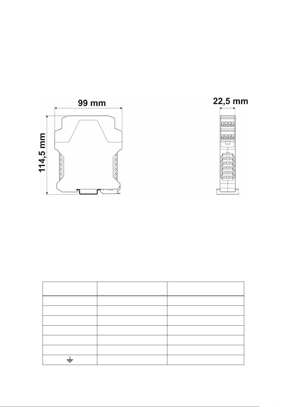
3.1 Mechanical Installation .......................................................................................... 7
3.2 Load Cell Connection............................................................................................. 7
3.3 Analogue Output Connection................................................................................ 8
3.4 Changing the Analogue Output............................................................................. 9
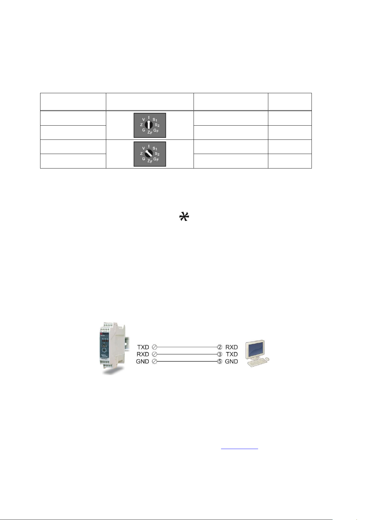
3.5 Serial Port Connection........................................................................................... 9
3.6 Commissioning....................................................................................................... 9
4. Adjustments................................................................................................... 10
4.1 Adjustment with Rotary Switches........................................................................10
4.2 Fast Adjustment to Nominal Output Range.........................................................12
4.3 eCal Electronic Adjustment Via xFace Software.................................................12
4.4 Adjustment (eCal) With PLC.................................................................................13
4.5 Testing the Scale Performance ............................................................................15
5. Setpoints ........................................................................................................ 16
5.1 Setpoint Connection..............................................................................................16
5.2 Setpoint Adjustment..............................................................................................16
5.3 Adjustment to the Load on the Scale...................................................................16
5.4 Adjustment by Measuring the Analog Output.....................................................16
6. Operation Mode ............................................................................................. 17
7. Programming With xFace Software Over RS232 ........................................ 18
7.1 Installation of xFace Software ..............................................................................18
7.2 xFace Software......................................................................................................18
8. Trouble Shooting........................................................................................... 20

FAA-28, Technical Manual, Rev.1.1.0 February 2022
Page 2 of 21
RIGHTS AND LIABILITIES
1. Safety Instructions
CAUTION! READ this manual BEFORE operating or servicing this equipment. FOLLOW
these instructions carefully. SAVE this manual for future reference. DO NOT allow untrained
personnel to operate, clean, inspect, maintain, service, or tamper with this equipment.
ALWAYS DISCONNECT this equipment from the power source before cleaning or
performing maintenance. CALL FLINTEC ENGINEERING for parts, information, and service.
WARNING! ONLY PERMIT QUALIFIED PERSONNEL TO SERVICE THIS EQUIPMENT.
EXERCISE CARE WHEN MAKING CHECKS, TESTS AND ADJUSTMENTS THAT MUST
BE MADE WITH POWER ON. FAILING TO OBSERVE THESE PRECAUTIONS CAN
RESULT IN BODILY HARM.
WARNING! FOR CONTINUED PROTECTION AGAINST SHOCK HAZARD CONNECT TO
PROPERLY GROUNDED OUTLET ONLY. DO NOT REMOVE THE GROUND PRONG.
WARNING! DISCONNECT ALL POWER TO THIS UNIT BEFORE REMOVING THE FUSE
OR SERVICING.
WARNING! BEFORE CONNECTING/DISCONNECTING ANY INTERNAL ELECTRONIC
COMPONENTS OR INTERCONNECTING WIRING BETWEEN ELECTRONIC EQUIPMENT
ALWAYS REMOVE POWER AND WAIT AT LEAST THIRTY (30) SECONDS BEFORE ANY
CONNECTIONS OR DISCONNECTIONS ARE MADE. FAILURE TO OBSERVE THESE
PRECAUTIONS COULD RESULT IN DAMAGE TO OR DESTRUCTION OF THE
EQUIPMENT OR BODILY HARM.
CAUTION! OBSERVE PRECAUTIONS FOR HANDLING ELECTROSTATIC SENSITIVE
DEVICES.
All rights reserved.
No part of this publication may be reproduced, stored in a retrieval system, or transmitted in any form or by any
means, mechanical, photocopying, recording, or otherwise, without the prior written permission of Flintec
GmbH.
No patent liability is assumed with respect to the use of the information contained herein. While every
precaution has been taken in the preparation of this book, FLINTEC assumes no responsibility for errors or
omissions. Neither is any liability assumed for damages resulting from the use of the information contained
herein.
The information herein is believed to be both accurate and reliable. FLINTEC, however, would be obliged to be
informed if any errors occur. FLINTEC cannot accept any liability for direct or indirect damages resulting from
the use of this manual.
FLINTEC reserves the right to revise this manual and alter its content without notification at any time.
Neither FLINTEC nor its affiliates shall be liable to the purchaser of this product or third parties for damages,
losses, costs, or expenses incurred by purchaser or third parties as a result of: accident, misuse, or abuse of
this product or unauthorized modifications, repairs, or alterations to this product, or failure to strictly comply with
FLINTEC operating and maintenance instructions.
FLINTEC shall not be liable against any damages or problems arising from the use of any options or any
consumable products other than those designated as Original FLINTEC Products.
NOTICE: The contents of this manual are subject to change without notice.
Copyright © 2016 by Flintec GmbH, 74909 Meckesheim, Bemannsbruch 9, Germany

FAA-28, Technical Manual, Rev.1.1.0 February 2022
Page 3 of 21
2. Front View, Features and Specifications
High speed analog load cell transmitter FT-28 has very high accuracy and long term
stability with its high tech design. Its high performance electronic calibration via
RS232C serial port without any test weight and fast calibration without measuring
output signal reduces commissioning and service times.
This high tech instrument gives the system designers a lot of advantages to increase
the system reliability and to reduce the installation and service times. Besides the
traditional analog output adjustment with any test weight, the electronic calibration
eCal and fast calibration with 20% max. test load reduces the calibration time.
All analog outputs of the instruments are matched in the production to perform
calibration at PLC and for changing the instrument without recalibration in service.
There are 8 positioned rotary switches and annunciator LEDs in front of the
instrument. The front view and pin descriptions of FAA-28 is shown below.
Pin Name
Definition
LOAD CELL CONNECTION
+ Ex
+ Excitation
- Ex
- Excitation
+Se
+Sense
-Se
-Sense
+ Si
+ Signal
- Si
- Signal
Shield and Protective ground
ANALOGUE OUTPUT
I
Current output
V
Voltage output
G
GND
SERIAL CONNECTION
TX
TxD ( RS232C )
RX
RxD ( RS232C )
G
Ground ( RS232C )
-
Zeroing input (0V)
+
Zeroing input (+24V)
SETPOINT CONNECTION
Q1
Digital Output 1
Q2
Digital Output 2
Com
Digital Outputs Common
POWER SUPPLY
24V
+24VDC
0V
0VDC
FAA-28

FAA-28, Technical Manual, Rev.1.1.0 February 2022
Page 4 of 21
Meanings of the positions of rotary switches;
Programming (Prog)
switch
V
Voltage output type run
(refer to page 9)
I
Current output type run
(refer to page 9)
S1
Setpoint 1 adjustment
(refer to page 17)
S2
Setpoint 2 adjustment
(refer to page 17)
Z
Zero adjustment
(refer to page 11)
G
Gain adjustment with test weight
(refer to page 11)
ZF
Fast zero adjustment
(refer to page 13)
GF
Fast gain adjustment with 20% test
weight of Maximum scale capacity
(refer to page 13)
Adjustment (Adj)
switch
0
Operation mode (Run)
Special Functions in “Fast Adjustment, “Setpoint
Adjustment”
LEDs
Annunciator LEDs (Run, Output type, Error).
Refer to chapter 9
Features
•Minimized zero and span drifts due to its microcontroller technology and high
accuracy, very low temperature drift, 24 bits ADC and 16 bits DAC converters.
•Long time stability and low temperature drifts eliminate the frequent
readjustment period.
•Very easy and user friendly digital adjustment via rotary switches located on
the front of the instrument.
•Programmable digital adaptive anti-vibration filters to minimize environmental
vibrations.
•eCal- electronic calibration without weights and digital filter adjustment via
RS232C port and xFace PC software.
•Fast calibration feature to reduce the adjustment time and to minimize
adjustment error.
•Calibration at PLC does not require readjustment after changing instrument
because of matching in the production.
•1 zeroing input and 2 free relay contact outputs for alarm or controlling valves,
gate etc.

FAA-28, Technical Manual, Rev.1.1.0 February 2022
Page 5 of 21
TECHNICAL SPECIFICATIONS
Analogue input range
-18 mV … +18 mV
Min. input range
< 0.8 mV
Linearity
< % 0.01
Temperature drift
< 0.005 % FSR / ºC
Converters
24 bit Delta-Sigma ratiometric ADC with integral analog and
digital filters, high EMC immunity
16 bit very low drift DAC
Internal resolutions
16 000 000 counts ADC
External resolution
Analogue output changes up to 60000 steps
Output update rate
Up to 800 conversions per second
Calibration
With rotary switches in the front with test load.
Fast calibration with 20% of max. weighing range
Electronic calibration via PC.
Preadjusted instrument for calibration at PLC
Digital Filter
Programmable 9 step adjustable digital adaptive filter.
Analogue outputs
Current output for 0-20 mA and 4-20 mA or
voltage output for 0- 5 V and 0-10 V.
Max. cable length
300 meter
Max. load resistance
(voltage output)
500 Ω
Set point
2 free programmable setpoints.
Digital Output
2 relay contacts for setpoints, 230 VAC or 30 VDC, 1 A.
Digital Input
1 opto-isolated input for zeroing, 12 … 28 VDC, 10mA
Load cell excitation
5 VDC
Number of coad cells
Up to 8 units of 350 or 18 units of 1100 (min. 43 )
Load cell connection
4- or 6- wire technique
Power supply
12 … 28 VDC, 0.2 A
Operation Temperature
-15°C …+55°C at 85% RH max, non-condensing
EMC Immunity
Class E2
Enclosure
Polyamide, for DIN-rail mount, IP20
Dimensions
Front Width:22,5 mm, Front Length: 99 mm , Height:114,5mm

FAA-28, Technical Manual, Rev.1.1.0 February 2022
Page 6 of 21
3. Installation and Commissioning
Recommendations
Warning:Please care the following warnings for designing the control cabinet which
will increase your system reliability.
The control cabinet should be designed so that instrument can operate safely.
The panel should be placed in clean area, if possible not getting direct sun light, with
a temperature between -15 ºC and +55 ºC, humidity not exceeding 85% non-
condensing. All external cables should be installed safely to avoid mechanical
damages.
FAA-28 instruments are very low level signal measuring instruments. To avoid
electrical noise, FAA-28 should be separated from the equipments that produce
electrical noise. Preferable use metal cabinet against radio frequency interference
and the cabinet shall be connected to ground against the electromagnetic
disturbances. Load cell cable and analog output cable trays must be separated from
others, if possible. If there are noise-generating equipments such as heavy load
switches, motor control equipments, inductive loads etc., please be careful against
the EMC interference in the cabinet. Connect parallel reverse diodes to the DC
inductive loads like relays, solenoids etc. to minimize voltage peaks on the DC power
lines.
All load cell and analogue output cables coming to the control cabinet shall be
shielded.
Warning: Control cabinet design and proper installation increases reliability and
performance of the instrument. Please do not forget that the instrument must be
powered off before inserting or removing any peripheral connector.
Follow the installation and commissioning steps described below carefully to prevent
unwanted results after installation.

FAA-28, Technical Manual, Rev.1.1.0 February 2022
Page 7 of 21
3.1 Mechanical Installation
The place where you will use/install your instrument should be clean, not getting
direct sunlight if possible, with a temperature between -15ºC and +55ºC, 85%
maximum relative humidity non-condensing. Install the instrument on the DIN rail in
the cabinet.
The instrument mechanical drawing
3.2 Load Cell Connection
The load cell wiring should be made carefully before energizing to avoid damages of
the instrument and load cells. In 4-wire installations the sense and excitation pins
with the same polarity should be short circuited at the connector side. If you have
junction box, use 6 wire cable between FAA28 and the junction box, and short circuit
these pins at junction box for better performance. The input resistance of the load
cells that you want to connect should be more than 43 Ω.
Pin Name
6 Wire Load Cell
Connection
4 Wire Load Cell
Connection
+Ex
+ Excitation
+ Excitation
+Se
+ Sense
Short circuit to + Excitation
-Ex
-Excitation
Short circuit to - Excitation
-Se
-Sense
- Excitation
+Si
+ Signal
+ Signal
-Si
-Signal
- Signal
Shield
Shield

FAA-28, Technical Manual, Rev.1.1.0 February 2022
Page 8 of 21
3.3 Analogue Output Connection
Only one of the analog output types can be used at the same time and has to be
selected in the setup type. Install the analog output measuring instrument for
adjustment, e.g. multimeter.
Pin Name
Definition
I
Current Output
V
Voltage Output
G
GND
Shield
Current output connection
Voltage output connection

FAA-28, Technical Manual, Rev.1.1.0 February 2022
Page 9 of 21
3.4 Changing the Analogue Output
FAA-28 sets its analog output according to the table below at power on. Turn the
programming switch and connect TxD and RxD pins as indicated in the table below
before power on the instrument to set analog output type and its signal level.
Analogue
Output Range
Prog. Switch Position
TxD & RxD pins
V / I LED
4 - 20 mA
Open circuited
On
0 - 20 mA
Short circuited
Off
0 - 10 VDC
Open circuited
Flash
0 - 5 VDC
Short circuited
Blinking
You can also set the analog output type after power on as;
•Turn the programming switch to the analog output type (to V or I position)
•Connect or disconnect TxD and RxD pins according the table above to set the
output range
•Turn the adjustment switch to the position. After 2 seconds turn in back to
the “0“- position (if the instrument is powered on before)
The analogue output type can be followed by the V/I LED on front of the instrument
after running it (refer to table above ) .
After set up the analog output of the instrument according to the table above go to
the next step.
3.5 Serial Port Connection
3.6 Commissioning
Double check the following issues before energizing the instrument.
•Check Mechanical installation, grounding, load cell connection and power
supply connection
•Check the analogue output set up described in chapter 4.4
•The analogue output cabling should be done for the same analogue output
type
•The adjustment (Adj) rotary switch shall be at “0“ - position

FAA-28, Technical Manual, Rev.1.1.0 February 2022
Page 10 of 21
4. Adjustments
4.1 Adjustment with Rotary Switches
To start the adjustment the programming switch should be at analog output type
position, Vor I.
Zand Gpositions of the programming switch are used for performing zero and gain
adjustments in sequence. Analog output is changed by turning the adjustment switch
as described in the table below.
Adjustment rotary
switch position
Rotary switch description
Run
LED
No change, operation mode
On
Decrease ( - ) / Increase ( + ) in slow steps
Flash
Decrease ( - ) / Increase ( + ) in medium steps
Flash
Decrease ( - ) / Increase ( + ) in big steps
Flash
RUN LED flashes to indicate the instrument is not in operation mode.
Zero Adjustment
•Connect the measurement instrument (Multimeter is recommended) to the
analog output
•Unload the scale (the scale must be empty)
•Turn the programming switch to the Zposition from the analog output type
position
•Increase or decrease the analog output by adjustment rotary switch.
Never bring the adjustment switch to position in this adjustment. Turn the
adjustment switch to 0- position at the end of the adjustment.
•Turn the programming switch to analog output type position (Vor I) to start the
operation mode or to the Gposition to start gain adjustment
Gain Adjustment
•Connect the measurement instrument (Multimeter is recommended) to the
analog output
•Load the scale with a known load
•The analog output value should be calculated for the applied load

FAA-28, Technical Manual, Rev.1.1.0 February 2022
Page 11 of 21
Use the following formula for calculating the analog output value
Analog
Output
=
Minimum output
+
Maximum output –Minimum output
*
Load
Scale capacity
Example:
Scale capacity 100kg
Output range 4 –20 mA
Known Load 25kg
The 4-20mA analog output current will be at 25kg ;
Iout = 4mA + (( 20mA –4mA ) / 100kg ) * 25kg = 4 + 0.16 * 25 =
Iout = 8mA
The 0 –10VDC analog output voltage will be at 25kg:
Vout = 0 + (10V / 100kg ) * 25kg = 0,1 * 25 =
Vout = 2.5VDC
•Turn the adjustment switch to the Gposition from the analog output type
position you set before
•Increase or decrease the analog output by adjustment rotary switch to the
calculated output value
Never bring the adjustment switch to position in this adjustment. Turn the
adjustment switch to 0- position at the end of the adjustment
•Turn the programming switch to analog output type position for operation
mode (to V or I)
Important note: The instrument saves 4 different adjustments in its memory for the
voltage and current outputs and their ranges. Changing the analog output type it
automatically set the adjustment to the output range used before.

FAA-28, Technical Manual, Rev.1.1.0 February 2022
Page 12 of 21
4.2 Fast Adjustment to Nominal Output Range
You may perform fast adjustment method if you will set zero and gain to analog
output nominal values. This feature gives advantage to the instrument for small and
medium capacity weighing systems’ fast and easy adjustment.
Fast Zero Adjustment:
•Unload the scale
•Turn the programming switch to ZF position
•Turn the Adj. switch to position and turn it back to 0- position 2 seconds
later
•Turn the programming switch to analog output type position to start operation
mode or to GF position for gain adjustment.
For example, for 4 –20mA range and for 100kg capacity scale, unload the scale and
perform fast adjustment to set the output to 4mA.
Fast Gain Adjustment:
•Load the scale to the 20% of the maximum capacity (if scale capacity is
100kg, load 20 kg)
•Turn the programming switch to GF position.
•Turn the Adj. switch to position and turn it back to “0”- position 2 seconds
later
•Turn the programming switch to analog output type position for operation
For example, for 4 –20mA range and for 100kg capacity scale, load the scale 20kg
test weight and perform fast gain adjustment to set the output to 7,2mA at this load.
The output will be 20mA at 100kg loading.
4.3 eCal Electronic Adjustment Via xFace Software
The adjustment of high capacity tanks and silos are very difficult in practice and takes
very long time. You may save a lot of time by eCal adjustment by entering theoretical
scale and load cell values to the instrument instead of loading the scale. Due to the
production process of FAA-28, eCal accuracy is very high. Adjustment with eCal is
performed via RS232 port of the instrument and can be comfortable executed with
xFace software. Refer to chapter 8 for installation and using the software.
For increasing the eCal accuracy you must enter the specific load cell rated output,
which is printed on “Final Data Summary” attached to every Flintec load cell. Using
more than one load cell an arithmetic average of all load cells must be calculated.

FAA-28, Technical Manual, Rev.1.1.0 February 2022
Page 13 of 21
4.4 Adjustment (eCal) With PLC
All instruments are adjusted in the production to operate in its analog output range
between 0mV and 10mV load cell signal as default. For example, if the instrument is
at factory default values and programmed to operate 4 –20mA output range, the
output will be 4mA at 0mV and 20mA at 10mV load cell signal (only for 2mV/V load
cells).
Changing the FAA-28 instrument a recalibration is not required due to matching
instruments in production by Flintec.
Warning: If the instrument was adjusted before and its factory defaults are changed,
you should load factory defaults with xFace.
FAA-28 Programming via RS232C
FAA-28 can be electronically calibrated via RS232C serial interface by commands or
by xFace software. If you want to use your own software to calibrate the FAA-28 from
your PLC or PC, you may use the commands below. The yellow colored bytes are
the data in the command and blue colored bytes are check sum in this document.
Output type setting and eCal electronic calibration should be done in sequence.
RS232C PORT SETTING :
Adjust your PC or PLC serial port as 9600, 8 None 1.
DATA STRUCTURE :
ASCII, HEX DATA and CR (Carriage Return) at the end of the command.
COMMANDS: Descriptions
1. Analog output type setting:
a) 4 - 20mA setting:
Command: @01100000000102000BE1 Set to 4-20 mA range
Response: @011000000001EE ACK
b) 0 - 20mA setting:
Command: @011000000001020014D8 Set to 0-20 mA range
Response : @011000000001EE ACK
c) 0 - 10VDC setting :
Command: @01100000000102000AE2 Set to 0-10 VDC range
Response : @011000000001EE ACK
d) 0 - 5VDC setting :
Command: @011000000001020013D9 Set to 0-5 VDC range
Response : @011000000001EE ACK

FAA-28, Technical Manual, Rev.1.1.0 February 2022
Page 14 of 21
2. eCal procedure steps: Descriptions
Step 1 START eCal
Command: @011000000001020001EB Start the eCal process.
Response: @011000000001EE ACK
Step 2. Total Load cell Emax entry
Command: @01100003000204000001F4F1 Total LC is 500kg.
Response: @011000030002EA ACK
Step 3. Average Load cell mV/V entry
Command: @0110000500020400004E2F67 LC sensitivity: 2.0015mV/V.
Response: @011000050002E8 ACK
Step 4. Estimated Dead load entry
Command: @0110000700020400000000E2 Dead load is 0kg.
Response: @011000070002E6 ACK
Step 5. Scale Capacity entry
Command: @01100009000204000000FAE6 Scale capacity is 250kg.
Response: @011000090002E4 ACK
Step 6. SAVE with estimated dead load value
Command: @011000000001020007E5 Save the eCal values.
Response: @011000000001EE ACK
Or SAVE with automatic zero adjustment.
Unload the scale and send the command below
to start the zero adjustment.
Command: @011000000001020015D7 Save eCal with Zero Adj
Response: @011000000001EE ACK
Step 7. APPLY
Command: @011000000001020009E3 Apply the calibration.
Response: @011000000001EE ACK
Step 8. STOP eCal
Command: @011000000001020002EA Stop the eCal process
Response: @011000000001EE ACK
3. Digital Filter Setting:
Command: @011000220001020000CA Set the Fast filter
Command: @011000220001020001C9 Set to Medium filter
Command: @011000220001020002C8 Set to Slow filter
Response: @011000220001CC ACK

FAA-28, Technical Manual, Rev.1.1.0 February 2022
Page 15 of 21
4. Load Factory Defaults: Descriptions
Command: @011000240001025AA5C9 Set to factory default.
Response: @011000240001CA ACK
CHECKSUM CALCULATION :
CSUM = 0 –(Slave_Add + Function + … + Last_data)
(STX and CSUM are neglected while calculating CSUM)
Example
For Medium (1) filter: @011000220001020001XX
CSUM = 0 –( 01+10+00+22+00+01+02+00+01)
= 0 –37
= C9
Command is @011000220001020001C9 < Carriage Return >
4.5 Testing the Scale Performance
You have to check the scale performance by testing the scale eccentricity, scale
linearity at loading up to maximum loading value, repeatability etc. before using it.

FAA-28, Technical Manual, Rev.1.1.0 February 2022
Page 16 of 21
5. Setpoints
5.1 Setpoint Connection
FAA-28 has 2 free relay contact output. These outputs can be connected to
maximum 230VAC or maximum 30VDC, maximum 1A loads. Reverse diode
connection to the DC loads is recommended to increase the relay contact life and to
reduce the disturbances. Outputs connection is;
5.2 Setpoint Adjustment
The instrument closes the relay contacts if the weight value is higher than the
adjusted setpoint. These contact signals can be used to stop charging or discharging
or produce alarm signal. You can apply two methods to adjust setpoints.
5.3 Adjustment to the Load on the Scale
Setpoint can be adjusted to the load value on the scale:
•Load the scale to the value you want to produce setpoint signal
•Turn the programming switch to S1 (or S2) position from operation position
(from Vor Iposition)
•Turn the Adj. switch to positions position and turn it back to 0- position
2 seconds later
•Turn the programming switch to analog output type position for operation
mode (Vor Iposition) or to other setpoint position to adjust it
5.4 Adjustment by Measuring the Analog Output
You can adjust the setpoint by measuring the analogue output value without loading
the scale:
•Connect the measuring instrument to the analog output.
•Turn the programming switch to S1 (or S2) position from operation position
(from Vor Iposition).
•Increase or decrease the analog output by adjustment rotary switch (refer to
table in chapter 5.1 ).
Do not bring the adjustment switch position to position in this adjustment.
The adjustment switch must be at 0- position at the end of the adjustment.
•Turn the programming switch to analog output type position to start operation
(Vor Iposition) or to other setpoint position to adjust it.

FAA-28, Technical Manual, Rev.1.1.0 February 2022
Page 17 of 21
6. Operation Mode
There are 3 LEDs and 2 rotary switches on the front panel of FAA-28. The rotary
switches are being used for adjustment as described in chapter 4.4 and the LEDs
have different meanings in operation and setup type as indicated below.
Analogue
Output Range
Prog. Switch
position
Adj. Switch
position
TxD & RxD
pins
V / I LED
(after power
on)
4 - 20mA
Open circuited
On
0 - 20mA
Short circuited
Off
0 - 10VDC
Open circuited
Flash
0 - 5VDC
Short circuited
Blinking
The status of the LEDs in the operation type is given in the table below. Refer to
chapter 9 in case of the Err LED turns on.
The analogue output signal also gives information about the status of the system and
the weighing process to inform PLC as:
Condition
4-20mA
output
0-20mA
output
0 –10V
output
0 –5V
output
Operation mode
X
X
X
X
Programming
X
X
X
X
The weight is over the range
(Over signal to PLC)
24mA
24mA
11V
5,5V
The weight is under the range
(Under signal to PLC)
0mA
0mA
-4.0V
-4.0V
“Error” signal to PLC
0mA
0mA
0V
0V
“ADC is out of operating range” error to
PLC
24mA
24mA
11V
5,5V

FAA-28, Technical Manual, Rev.1.1.0 February 2022
Page 18 of 21
7. Programming With xFace Software Over RS232
FAA-28 has RS232C serial interface to perform eCal electronic calibration and to
adjust filter, setpoint values and to follow status by using xFace software installed on
a PC.
For installing the xFace software, which is supplied with the instrument or can be
downloaded from www.flintec.com, follow the steps described below.
7.1 Installation of xFace Software
•Close all applications on your PC
•Insert the CD that contains the xFace software v2.03 or higher into the CD-
ROM drive
•Double click “Setup.exe” to start the installation. The setup Wizard will be
displayed
•Follow the menus in the setup wizard step by step
•After finishing the installation, the Setup Wizard will inform you about the
success of the software installation. Click the OK button
•After closing the Setup Wizard you can start to use the xFace software
7.2 xFace Software
For programming instrument via xFace follow the instructions below;
1. Power off the instrument.
2. Connect the instrument to PC as
shown in chapter 4.5 to use xFace
software and run the software.
Select FAA-28 and press “OK”
button.
3. Select the Com-port and press
on “Connect” to connect to
the instrument.

FAA-28, Technical Manual, Rev.1.1.0 February 2022
Page 19 of 21
4. Select the analog output type.
5. Enter Total Load Cell capacity,
Average Load Cell Output,
Scale Capacity and
Estimated Dead Load.
6. Press “Write eCal Data to
Transmitter” button on the
monitor to perform eCal.
7. Unload the scale and Press
“eCal with Zero Adjustment“
button on the monitor.
8. Adjust filter value and setpoints in section “Setup”.
9. In section “Status” instrument information are available.
10.Power off the instrument before disconnecting from PC. Bring the
programming switch to the analog output type position and apply the
connection between TxD and RxD pins which is described in chapter 7 to set
the analog output type.
11. Turn the adjustment switch position to “0“ - position.
12.Power on the instrument for operation.
After performing eCal as described in the software, check the performance of your
system.
You may adjust to instrument to factory default by xFace, if it is changed before.
Table of contents
Other Flintec Amplifier manuals