Flomasta 5059340241562 User manual

23 4
1
This file is the property of Kingfisher Group Plc. No copying, alteration or amendment ispermitted without
written authorisation from the Kingfisher Brand Team.
V1.1
PROCESS
BLACK
SEPARATIONS JOB INFO
VERSION #
PID #: 216069_s1_s1
Agency Job #:
Product Description:
Central Heating Pump
17/06/21
Vijay
25/06/21
Wilson
08/07/21
Manisha
XX/XX/21
XXXX
XX/XX/21
XXXX
Brand: Flomasta
Brand Contact: Stephanie Rankin
Barcode: 5059340241562
Vendor: Wilo
No. of New Line Drawings: 0
Page Size: A5 / No. of Pages:
PLEASE NOTE THAT “SAFETY” AND “ASSEMBLY”
MANUALS SHALL BE PRINTED SEPARATELY
DO NOT PRINT THIS PAGE -
IT IS FOR INFORMATION ONLY
Artwork done by Impala Services Ltd
5
216069_s1_s1-5059340241562-Flomasta-A5-IM-Easy-V03.indd 1216069_s1_s1-5059340241562-Flomasta-A5-IM-Easy-V03.indd 1 08-07-2021 15:56:2708-07-2021 15:56:27

V10721 BX220IM
5059340241562
216069_s1_s1-5059340241562-Flomasta-A5-IM-Easy-V03.indd 1216069_s1_s1-5059340241562-Flomasta-A5-IM-Easy-V03.indd 1 08-07-2021 15:56:2708-07-2021 15:56:27
Contents
02
Product description 04
Safety 05
Installation
06
Use 11
Care and Maintenance
14
216069_s1_s1-5059340241562-Flomasta-A5-IM-Easy-V03.indd 2216069_s1_s1-5059340241562-Flomasta-A5-IM-Easy-V03.indd 2 08-07-2021 15:56:2808-07-2021 15:56:28
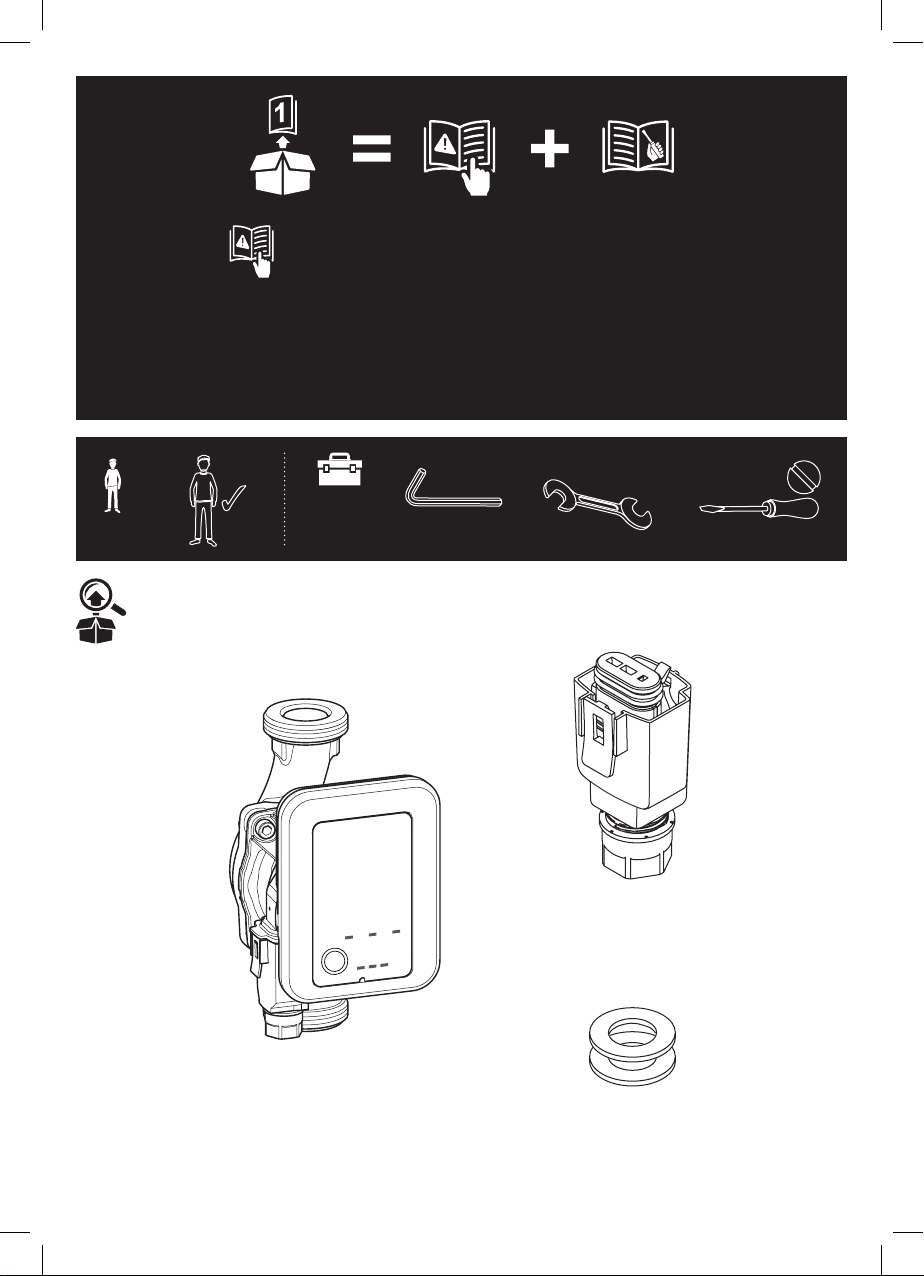
x ?
[01] x 1
[02] x 1
[03] x 1
5mm
EN IMPORTANT - These instructions are for your safety.
Please read through them thoroughly prior to installation
and retain them for future reference.
0.6mmx3.5mm
216069_s1_s1-5059340241562-Flomasta-A5-IM-Easy-V03.indd 3216069_s1_s1-5059340241562-Flomasta-A5-IM-Easy-V03.indd 3 08-07-2021 15:56:2908-07-2021 15:56:29
2
1
3
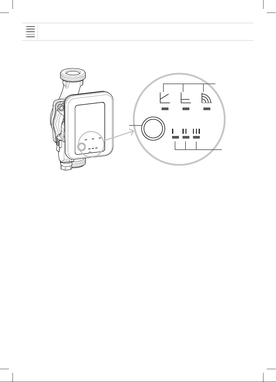
1. Control mode 2. Operating button 3. Characteristic curve
The pump consists of a hydraulic system, a glandless motor with a permanent magnet rotor, and an
electronic control module with integrated frequency converter.
The control module contains an operating button and LEDs for setting and displaying all
parameters.
Product description 4
216069_s1_s1-5059340241562-Flomasta-A5-IM-Easy-V03.indd 4216069_s1_s1-5059340241562-Flomasta-A5-IM-Easy-V03.indd 4 08-07-2021 15:56:2908-07-2021 15:56:29

Safety 5
Before you start
• Read these instructions through completely before installation.
• Not following these instructions can result in injury to persons or damage to the pump.
• Once installation work is complete, pass the instructions on to the end user.
• Keep the instructions near the pump. They can be used for reference if problems occur later.
• No liability will be accepted for damages resulting from failure to follow these instructions.
• Unpack and check the pump and all accessories upon receipt. Report any damage sustained in transit
immediately.
• Only ship the pump in its original packaging.
• The pump is to be protected from moisture, frost, and mechanical damage and must not be exposed to
temperatures outside the range of -10ºC to + 50ºC.
Safety
• The pump may only be installed by qualified personnel. The electrical connection may only be
established by a qualified electrician.
• This device can be used by children from 8 years old as well as by persons with limited physical, sensory,
or mental capabilities or lack of experience and knowledge provided they are supervised or have been
instructed in the safe use of the device and understand the dangers that may arise. Children must not
be not allowed to play with the device. Cleaning and maintenance by the user must not be carried out by
children without supervision.
Regulations
The current versions of the following regulations must be observed during installation:
• Accident prevention regulations
• VDE 0700/Part1 (EN 60335-1)
• Other local regulations (e.g. IEC, VDE)
Conversion and spare parts
Unauthorised modification and manufacture of spare parts will impair the safety of the product/personnel
and void the manufacturer’s declarations regarding safety.
• The pump must not be technically modified or converted.
• Opening the pump motor by removing the plastic lid is not permitted.
• Only use original spare parts.
Electrical current
There is a danger of electric shock when working with electrical current. For this reason:
• Switch off the power before beginning work on the pump, confirm that the system is voltage-free, and
ensure that it cannot be switched on again accidentally.
• Do not kink or pinch the power cable or allow it to come into contact with sources of heat.
• Never open the control module and never remove operating elements.
• The pump is protected against drips in accordance with IP protection class (see rating plate). Protect
the pump from water spray. Do not immerse in water or other fluids.
• The connection must be secured by means of a residualcurrent device (RCD).
216069_s1_s1-5059340241562-Flomasta-A5-IM-Easy-V03.indd 5216069_s1_s1-5059340241562-Flomasta-A5-IM-Easy-V03.indd 5 08-07-2021 15:56:2908-07-2021 15:56:29
DANGER: Before starting work, make sure that the pump is disconnected
from the power supply.
• Provide a weather-proof, frost-free, dust-free, and wellventilated room for the installation.
• Choose an easily accessible installation site.
• Prepare the installation site so that the pump can be installed without being subjected to mechanical
stresses. If necessary, support or secure piping on both sides of the pump.
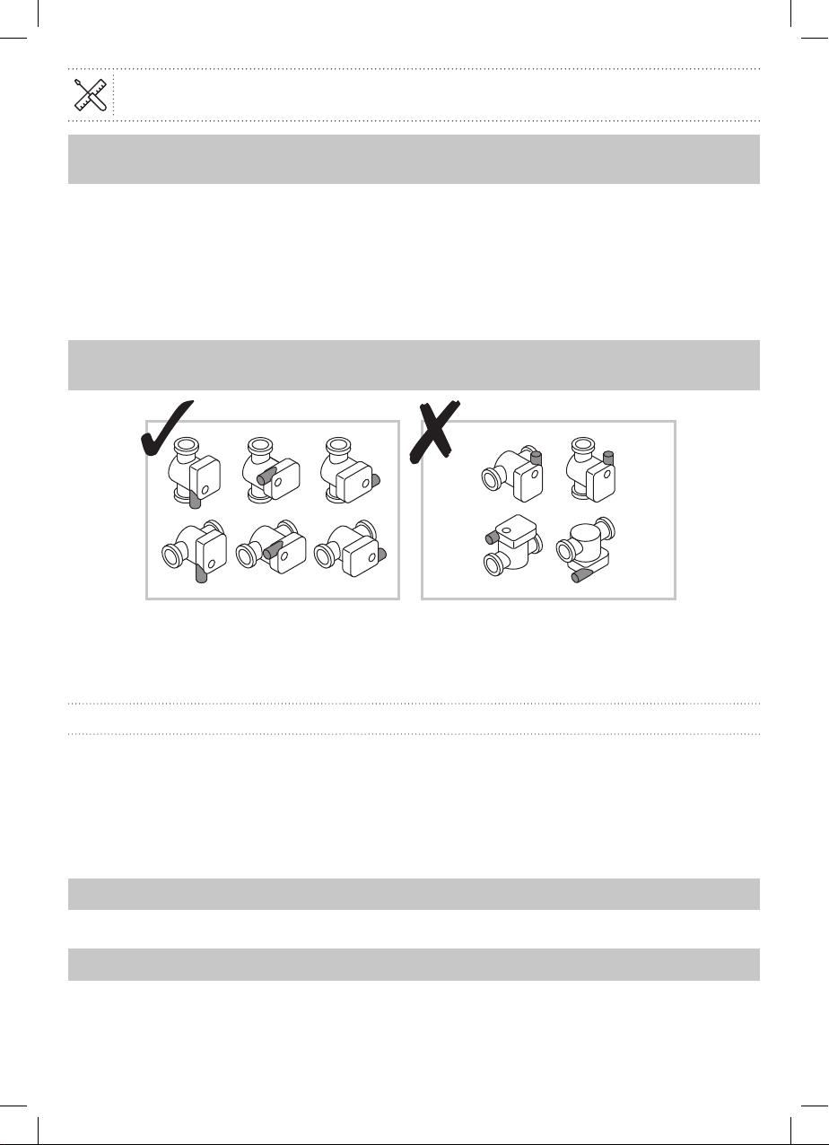
NOTICE: Provide shut-off devices upstream and downstream of the pump to facilitate potential future
pump replacement. Perform the installation in a way that prevents leaking water from dripping onto the
control module. To do this, align the upper gate valve laterally if necessary.
• Complete all welding and soldering work near the pump prior to the installation of the pump.
CAUTION: Dirt can cause the pump to fail. Flush the pipe system
beforeinstallation.
• Choose the correct installation position, with the pump motor in a horizontal position, from only the
positions shown above. Direction arrows on the pump housing indicate the direction of flow.
• If heat insulation work is necessary, only the pump housing may be insulated. The pump motor, module,
and condensate drainage openings must remain uncovered.
Turning the motor head
If the installation position of the module is changed, the motor housing must be turned as follows:
• If necessary, remove the thermal insulation shell.
• Loosen the interior hexagonal head screws.
• Turn the motor housing, including the control module.
NOTICE: In general, turn the motor head before the system is filled. When turning the motor head in a
system that has already been filled, do not pull the motor head out of the pump housing. Turn the motor
head with a small amount of pressure on the motor unit so that no water can come out of the pump.
CAUTION: Do not damage the housing seal. Replace damaged gaskets.
• Turn the motor head in such a way that the plug corresponds to the permitted installation position
shown above.
CAUTION: If the position is wrong, water can penetrate and destroy the pump.
• Turn in the interior hexagonal head screws.
• If applicable, re-mount the thermal insulation shell.
Installation
6
216069_s1_s1-5059340241562-Flomasta-A5-IM-Easy-V03.indd 6216069_s1_s1-5059340241562-Flomasta-A5-IM-Easy-V03.indd 6 08-07-2021 15:56:2908-07-2021 15:56:29
Installation
7
01
32mm
7mm
02 PE
NL
216069_s1_s1-5059340241562-Flomasta-A5-IM-Easy-V03.indd 7216069_s1_s1-5059340241562-Flomasta-A5-IM-Easy-V03.indd 7 08-07-2021 15:56:3108-07-2021 15:56:31
Installation
8
03
04
216069_s1_s1-5059340241562-Flomasta-A5-IM-Easy-V03.indd 8216069_s1_s1-5059340241562-Flomasta-A5-IM-Easy-V03.indd 8 08-07-2021 15:56:3308-07-2021 15:56:33

Installation
9
05
06 1
2
3
216069_s1_s1-5059340241562-Flomasta-A5-IM-Easy-V03.indd 9216069_s1_s1-5059340241562-Flomasta-A5-IM-Easy-V03.indd 9 08-07-2021 15:56:3408-07-2021 15:56:34

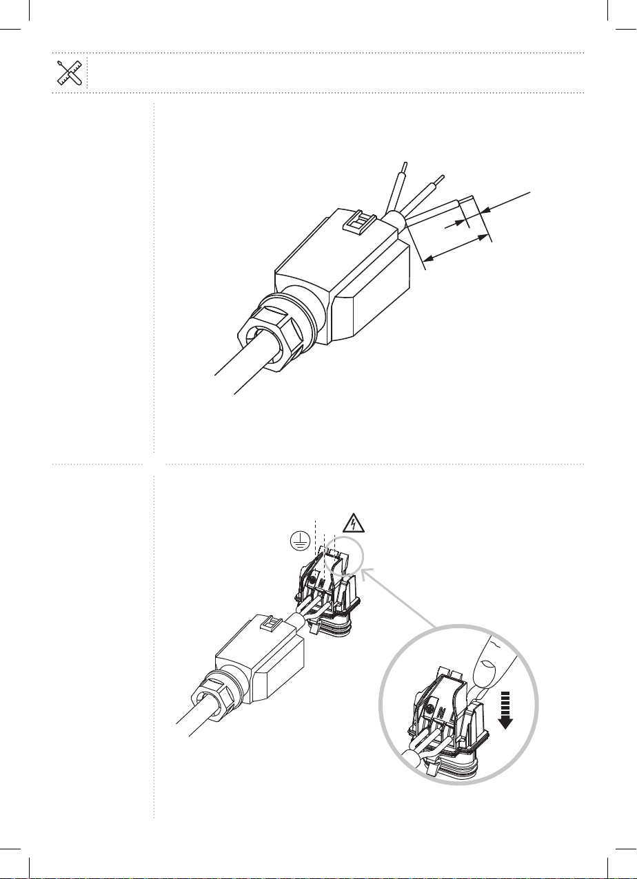
Electrical connection
DANGER: Work on the electrical connection must be performed only by a qualified
electrician and in accordance with national and local regulations. Before making
the connection, ensure that the connecting cable is not live.
• The mains voltage and current type must correspond to the rating plate specifications.
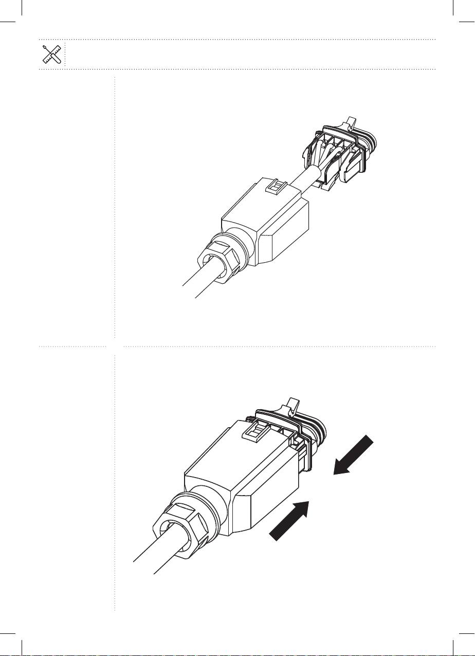
• Connect the plug (Step 01 to Step 05).
• Remove the plug [02] from the pump [01].
• Wire the plug [02] using Step 01 to 05 for reference.
• Mains connection: L, N, PE.
• Max. back-up fuse: 10A, slow-blow.
• Earth the pump in accordance with instructions.
• Dismantle the plug in accordance with Step 06. A screwdriver is required to do this.
• The electrical connection is to be established via a fixed connecting cable equipped with a connector
device or an all-pole switch with a contact opening width of at least 3 mm.
• To ensure drip protection and strain relief at the PG screwed connection, a connecting cable with an
adequate outer diameter is required (e.g. H05VV-F3G1.5).
• For pumps in systems with water temperatures above 90ºC, install a suitably heat-resistant connecting
cable.
• The connecting cable is to be laid in such a way that it can under no circumstances come into contact
with the pipe and/or the pump and motor housing.
• The switching of the pump using triacs / solid-state relays must be tested on a case-by-case basis.
CAUTION: Voltage pulsing during phase angle control or external control can
cause damage to electronic components.
CAUTION: Only operate the pump with sinusoidal AC voltage as stated on the
rating plate.
CAUTION: The switching of the pump using triacs / solid-state relays must be
tested on a case-by-case basis.
Commissioning/operation
WARNING: Depending on the pump or the system operating conditions
(fluidtemperature), the entire pump can become very hot. There is a risk
of burns upon coming into contact with the pump! Commissioning by
qualified personnel only!
Venting
• Fill and vent the system appropriately.
• The pump rotor space vents automatically after a short time in operation. This may cause noises. If
necessary, switch off and on again repeatedly to speed up the venting process. The pump will not be
harmed by dry running for short periods.
Installation
10
216069_s1_s1-5059340241562-Flomasta-A5-IM-Easy-V03.indd 10216069_s1_s1-5059340241562-Flomasta-A5-IM-Easy-V03.indd 10 08-07-2021 15:56:3408-07-2021 15:56:34

Intended use
• The circulators in this series are designed for warm water heating systems and similar systems with
constantly changing flows.
• The approved fluids are heating water in accordance with VDI 2035, and water/glycol mixture at a mixing
ratio of 1:1.
• If glycol is added, the delivery data of the pump must be corrected according to the higher viscosity
depending on the mixing ratio.
• Intended use includes the observation of these instructions as well as of specifications and labelling on
the pump.
• Any other use is regarded as improper use.
Control modes
H
Q
H H
Q Q
I
I
I
II II
II
III
III III
Variable differential pressure (Δp-v):
If the volume flow in the pipe network decreases, the pump reduces the delivery head by
half
(Step 08).
Optionally with three pre-set characteristic curves (I, II, III).
Constant differential pressure (Δp-c):
The control keeps the set delivery head constant irrespective of the volume flow delivered
(Step 09).
Optionally with three pre-set characteristic curves (I, II, III).
Constant speed (I, II, III):
The pump runs at three specified constant-speed settings (Step 10).
Setting the control mode
The control modes and corresponding characteristic curves are shown on the LED display in clockwise
succession.
1. Press the operating button briefly (approx. 1 second).
2. The LEDs display the set control mode .
3. The LEDs display the set characteristic curve .
The following demonstrates the display of the possible settings (example: constant speed / characteristic
curve III):
Use 11
216069_s1_s1-5059340241562-Flomasta-A5-IM-Easy-V03.indd 11216069_s1_s1-5059340241562-Flomasta-A5-IM-Easy-V03.indd 11 08-07-2021 15:56:3408-07-2021 15:56:34
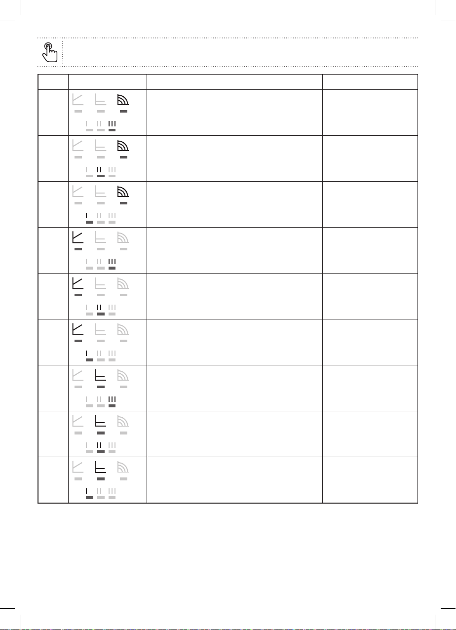
Use 12
LED display Control modet Characteristic curve
1. Constant speed III
2. Constant speed II
3. Constant speed I
4. Variable differential pressure Δp-v III
5.
Variable differential pressure Δp-v II
6. Variable differential pressure Δp-v I
7. Constant differential pressure Δp-c III
8. Constant differential pressure Δp-c II
9. Constant differential pressure Δp-c I
After pressing the button 9 times, the selection will have returned to the basic setting (constant speed /
characteristic curve III).
NOTICE: All settings and displays are retained if the mains supply is interrupted.
216069_s1_s1-5059340241562-Flomasta-A5-IM-Easy-V03.indd 12216069_s1_s1-5059340241562-Flomasta-A5-IM-Easy-V03.indd 12 08-07-2021 15:56:3508-07-2021 15:56:35

Technical Data
Flomasta 25-6
Connection voltage 1~230V±10%, 50Hz
Temperature class TF95
Protection class IP See rating plate
Energy Efficiency Index EEI * See rating plate
Nominal connection diameter
(Screwed connection)
DN25 (Rp 1)
Port-to-port length 130mm
Water temperatures at a max. ambient
temperature of +40ºC
-10ºC to + 95ºC
Max. ambient temperature -10ºC to + 40ºC
Max. operating pressure 6bar (600kPa)
Minimum inlet pressure at + 95ºC 0.3bar (30kPa)
* Reference value for the most efficient circulatzors: EEI ≤ 0.20
Use 13
216069_s1_s1-5059340241562-Flomasta-A5-IM-Easy-V03.indd 13216069_s1_s1-5059340241562-Flomasta-A5-IM-Easy-V03.indd 13 08-07-2021 15:56:3508-07-2021 15:56:35
Care and Maintenance 14
DANGER: Before starting any maintenance and repair work, disconnect the
pump from the power supply and make sure it cannot be switched back on by
unauthorised persons.
• Damage to the connection cable must always be repaired by a qualified electrician.
• Faults must only be remedied by qualified personnel!
WARNING: Risk of burns when touching the pump! Depending on the pump
or the system operating conditions (fluid temperature), the entire pump
can become very hot.
When removing the motor head or pump, hot fluid may be expelled under high pressure.
• Allow the pump to cool down first.
• Close the stop valves before removing the pump.
• There is always a strong magnetic field inside the motor. The permanent magnet rotor installed in the
pump can pose mortal danger to people with medical implants (e.g. pacemakers) during dismantling.
• Never open the motor and never remove the rotor.
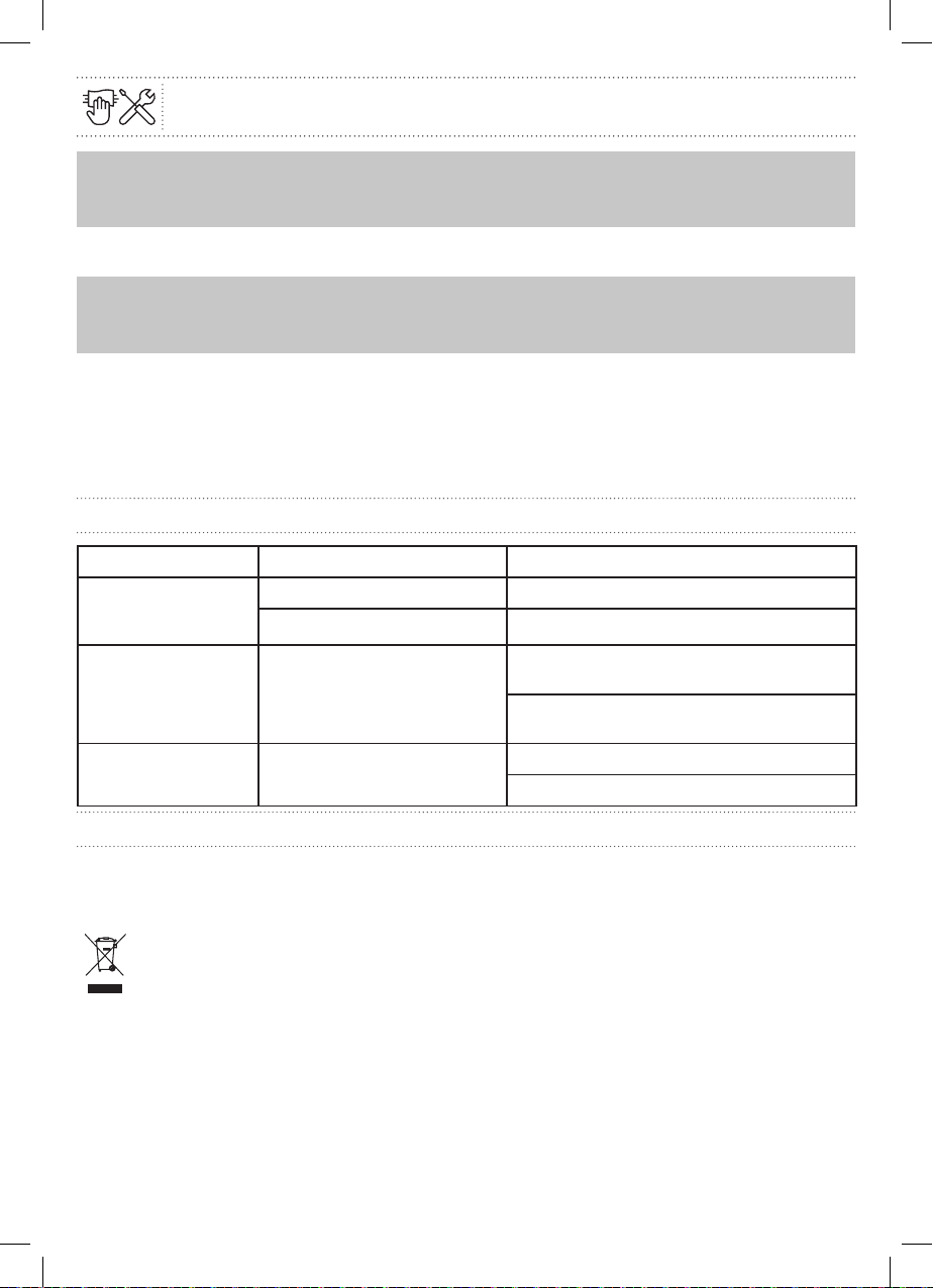
Troubleshooting
Fault Cause Remedy
Pump is not running
although the power
supply is switched on
Electrical fuse defective Check fuses
No voltage supply to the pump Resolve the interruption to the power supply
Pump is noisy Cavitation due to insufficient
suction pressure
Increase the system supply pressure within
the permissible range
Check the delivery head setting and set it to
a lower height if necessary
Building does not
warm up
Thermal output of the heating
surfaces is too low
Increase setpoint
Set control mode to Δp-c
Disposal
Information on the collection of used electrical and electronic products
Proper disposal and recycling of this product prevents damage to the environment and risk to personal
health.
NOTICE:
Disposal in domestic waste is forbidden!
Electrical and electronic products with this marker must not be disposed of in domestic waste.
• Use public or private disposal organisations when disposing of the product or parts of the product.
• For more information about proper disposal, please contact your local council or waste disposal office
or the supplier from which you obtained the product.
216069_s1_s1-5059340241562-Flomasta-A5-IM-Easy-V03.indd 14216069_s1_s1-5059340241562-Flomasta-A5-IM-Easy-V03.indd 14 08-07-2021 15:56:3508-07-2021 15:56:35
(EN) EU DECLARATION OF CONFORMITY
Product
• Flomasta Domestic Circulator Pump
• Flomasta 25.2-6-130
Name and address of the manufacturer or his authorised representative:
Kingfisher International Products B.V.,
Rapenburgerstraat 175E,
1011 VM Amsterdam,
The Netherlands
This declaration of conformity is issued under the sole responsibility of the manufacturer:
Object of the declaration
Product Model EAN
Flomasta Domestic Circulator Pump Flomasta 25.2-6-130 5059340241562
The object of the declaration described above is in conformity with the relevant Union harmonisation legislation:
2014/30/EU as amended Directive Electromagnetic compatibility
2014/35/EU Directive Electrical Safety: Low-voltage electrical equipment
2011/65/EU as amended Directive Restriction of the use of certain hazardous substances in electrical and electronic
equipment Products
References to the relevant harmonised standards used or references to the other technical specifications in relation to
which conformity is declared:
EN 60335–1:2012+A11:2014+A13:2017+A1:2019+A2:2019+A14:2019
EN 60335–2–51:2003+A1:2008+A2:2012
EN 61000–6–2:2005
EN 61000–6–3:2007+A1:2011;
EN 61000–6–4:2007+A1:2011
EN 16297–1:2012; EN 16297–2:2012
EN IEC 63000:2018;
Signed for and on behalf of/Signé par et au nom de/Podpisano w imieniu/Semnat pentru și în numele/
Firmado en nombre de/Assinado por e em nome de:
Kingfisher International Products B.V.,
Rapenburgerstraat 175E,
1011 VM Amsterdam,
The Netherlands
David Awe
Group Quality Director On: 28/05/2021
216069_s1_s1-5059340241562-Flomasta-A5-IM-Easy-V03.indd 15216069_s1_s1-5059340241562-Flomasta-A5-IM-Easy-V03.indd 15 08-07-2021 15:56:3608-07-2021 15:56:36
(UK) DECLARATION OF CONFORMITY
Product
• Flomasta Domestic Circulator Pump
• Flomasta 25.2-6-130
Name and address of the manufacturer or his authorised representative:
Kingfisher International Products Limited
3 Sheldon Square
London W2 6PX
United Kingdom
This declaration of conformity is issued under the sole responsibility of the manufacturer.
Object of the declaration
Product Model EAN
Flomasta Domestic Circulator Pump Flomasta 25.2-6-130 5059340241562
The object of the declaration described above is in conformity with the relevant legislation:
Electrical Equipment (Safety) Regulation 2016 as amended
Electromagnetic Compatibility Regulations 2016 as amended
The Restriction of the use of Certain Hazardous Substances in Electrical and Electronic Equipment Regulations 2012 as
amended
The Ecodesign for Energy-Related Products and Energy Information (Amendment) (EU Exit) Regulations 2019
References to the relevant designated standards used or references to the other technical specifications in relation to
which conformity is declared:
BS EN 60335–1:2012+A11:2014+A13:2017+A1:2019+A2:2019+A14:2019
BS EN 60335–2–51:2003+A1:2008+A2:2012
BS EN 61000–6–2:2005
BS EN 61000–6–3:2007+A1:2011
BS EN 61000–6–4:2007+A1:2011
BS EN 16297–1:2012; BS EN 16297–2:2012
BS EN IEC 63000:2018
Signed for and on behalf of:
Kingfisher International Products Limited
3 Sheldon Square
London W2 6PX
United Kingdom
David Awe
Group Quality Director On: 28/05/2021
216069_s1_s1-5059340241562-Flomasta-A5-IM-Easy-V03.indd 16216069_s1_s1-5059340241562-Flomasta-A5-IM-Easy-V03.indd 16 08-07-2021 15:56:3608-07-2021 15:56:36

Address 17
Manufacturer
UK Manufacturer:
Kingfisher International Products Limited,
3 Sheldon Square, London, W2 6PX,
United Kingdom
EU Manufacturer:
Kingfisher International Products B.V.
Rapenburgerstraat 175E
1011 VM Amsterdam
The Netherlands
www.kingfisher.com/products
EN www.diy.com
www.screwfix.com
www.screwfix.ie
Customer Helpline (Freephone)
UK 0800 324 7818 uk@kingfisherservice.com
Eire 1800 932 230 eire@kingfisherservice.com
To view instruction manuals online,
visit www.kingfisher.com/products
216069_s1_s1-5059340241562-Flomasta-A5-IM-Easy-V03.indd 17216069_s1_s1-5059340241562-Flomasta-A5-IM-Easy-V03.indd 17 08-07-2021 15:56:3608-07-2021 15:56:36
Table of contents
Popular Water Pump manuals by other brands

GÜDE
GÜDE Mr.Gardener GP 4600 INOX Translation of the original instructions

Beko
Beko BM33U Instructions for installation and operation

Becker
Becker VX 4.16 operating instructions

YATO
YATO YT-85330 Original instructions

Ingersoll-Rand
Ingersoll-Rand ARO PH10A-ASS-SST Operator's manual

Lincoln
Lincoln SKF FlowMaster II A Series User and maintenance instructions

Becker
Becker DVX 3.100 operating instructions

SAB
SAB F101 Instructions for use

Grundfos
Grundfos SR Service manual

Ingersoll-Rand
Ingersoll-Rand ARO WLM2203A 2 Series Operator's manual

Xylem
Xylem GOULDS XBGR Series Installation, operation and maintenance manual

Ampco Pumps Company
Ampco Pumps Company ZP1+ Series Maintenance manual addendum


