Explanation of safety
signals
Safety
Read and carefully observe these installation
instructions before installing, operating or
troubleshooting the referenced equipment.
Referenced equipment must be installed,
maintained and repaired exclusively by
persons familiar with the instructions.
Always disconnect power source (electric-
ity, air or hydraulic) from equipment, if appli-
cable, when it is not being used.
Adequate personal protection must be
used to prevent material from contacting the
skin or eyes.
If any fluid appears to penetrate the skin,
seek medical treatment immediately. Do not
treat injury as a simple cut. Tell attending
physician exactly what fluid was injected.
Failure to comply may result in personal
injury and/or damage to equipment.
Any other use not in accordance with
instructions will result in loss of claim for
warranty or liability.
• Never exceed maximum specification
ratings of the equipment.
• Do not misuse, modify parts, or use worn
and/or damaged parts.
•
Always read and follow the manufacturer’s
recommendations regarding the use of
protective clothing and equipment.
Overview
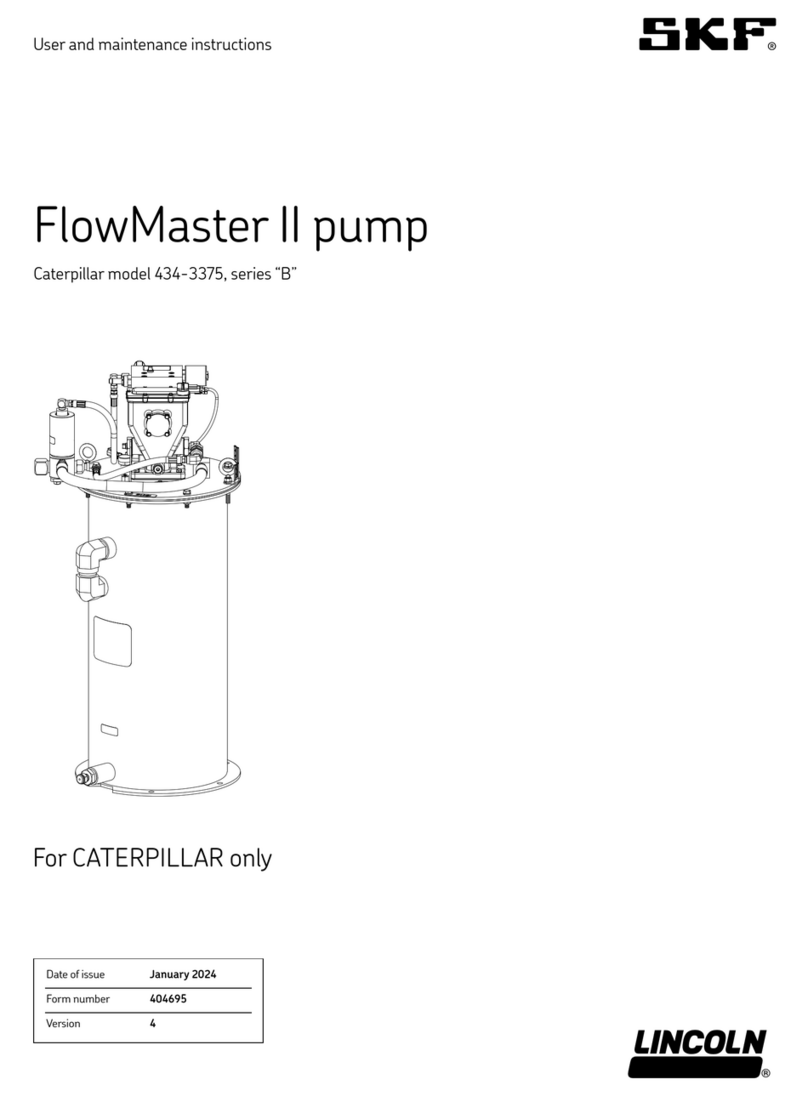
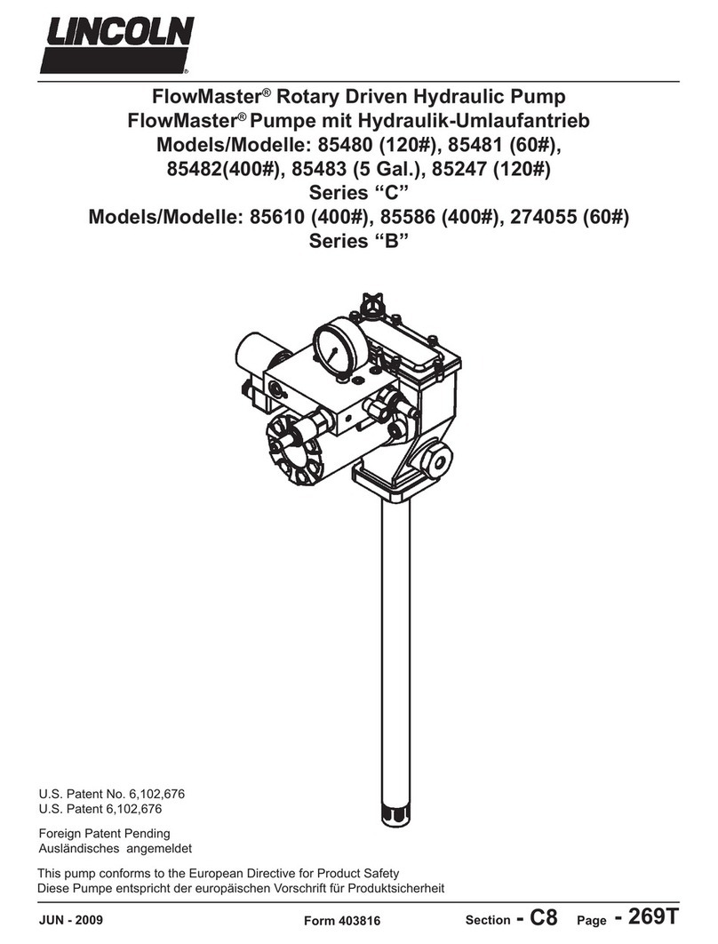
Model is a FlowMaster II rotary
driven pumping unit designed to operate
a Centro-Matic lubrication system.
The pump includes motor speed control
and built in circuit protection to prevent
control burnout.The pump is double acting,
dispensing lubricant on both “up” and
“down” strokes. The model also
includes:
• A in. (50,8 mm) follower plate.
• An electric float switch.
• A vent valve for relieving line pressure to
recharge the injectors.
• A mechanical shut-off valve.
This unit is for use with SL-V, SL-, SL-,
SL- and SL- series injectors.
Mechanical shut-off valve
The mechanical shut-off valve automatically
shuts off the filling of the reservoir without
power applied to the system.
As grease flows through the valve and into
the reservoir, the follower raises until it con-
tacts the pivot arm. The pivot arm then rai-
ses until it contacts the pin on the shut-off
valve and closes the valve. When the valve
closes, the flow of the grease to the reservoir
stops.
Shut off the fill pump and relieve pressure
between the fill pump and the shut-off valve
in order to disconnect the fill line safely.
Keep the pressure relief valve activated
until the supply line pressure on the gauge
falls below psi (13 bar). The fill line can
then be removed at the quick disconnect
point.
System specifications
Supply voltage V DC
Ambient operating
temperature
– to + °F
(–40 to +66 °C)
Container capacity lb (41 kg)
Mechanical shut-off valve specifications
Maximum operating
pressure
psi
(413,6 bar)
Operating temperature – to + °F
(–40 to +65 °C)
Port shut-off body 1/2NPTF
Contents
Safety . . . . . . . . . . . . . . . . . . . . . . . . .
Explanation of safety signals . . . . . . .
Overview . . . . . . . . . . . . . . . . . . . . . . .
Maintenance and repair . . . . . . . . . . .
CAUTION
Indicates a hazardous situation which,if not
avoided, could result in minor or moderate
injury.
WARNING
Indicates a hazardous situation which,if not
avoided will result in death or serious injury.
DANGER
Indicates a hazardous situation which,if not
avoided, will result in death or serious injury.
