Installation 7
For parts or assistance, call Flotec Customer Service at 1-800-365-6832
1. The pump leads are polarity sensitive; connect the
positive pump lead to the terminal labeled ‘Pump +’
and the negative pump lead to the terminal labeled
‘Pump –’.
NOTE: If the leads are reversed, the pump will run
backward and not pump water.
2. The vertical float switch leads are not polarity sensi-
tive; connect the float switch leads to the ‘Float
Switch’ tabs on the Charger/Controller. If you are
using two batteries, use the second set of terminals
and connect the second battery in the same manner.
Connect the
positive
(+) battery lead (red) to the
positive Charger/Controller terminal (red). Connect
the
negative
(–) battery lead (black) to the negative
terminal (black) on the Charger/Controller.
3. Test the float switch and the pump by lifting and
holding the float rod. The ‘Pump Status’ LED will
light continuously and the buzzer will beep steadily.
The pump should start after 3 seconds. If the pump
does not run, check all the connections and remake
them as necessary.
4. With the pump operating, press the ‘Silence Alarm’
button; hold for one second; release. The ‘Silenced
Alarm’ LED should illuminate and the buzzer should
stop sounding. To reset the buzzer (make it sound)
and extinguish the ‘Silenced Alarm’ LED, press the
‘Silence Alarm’ button again for one second.
5A. To stop the pump, lower the float switch; after 3
seconds the pump should stop, the ‘Pump Status’
LED should flash, and the buzzer should beep.
5B. Depress the ‘System Test’ button; hold it for one second;
release. The ‘Pump Status’ LED should stop flashing.
NOTE: During normal operation, the flashing ‘Pump
Status’ LED indicates that the pump has run in your
absence. See Table II, “Operating Code Displays”,
Page 9.
6. Press and hold ‘System Test’ button. All LEDs will
light up, pump will run and buzzer will sound.
Release the button and LEDs should go off, pump
should stop, buzzer should stop.
7. The ‘Battery Status’ LED indicates the battery
capacity when the A.C. power is off.
A. Continuously ‘ON” - the battery voltage is above
10.9 Volts Direct Current (10.9VDC) and
capacity is above 20%.
B. Slow Beep/Slow LED Flash - the battery’s
capacity is between 0 and 20%.
C. Fast Beep/Fast LED Flash - the battery is severely
discharged. The battery will continue to charge
(as long as the 115V AC power to the charger is
on) at the rate of .5 AH until the battery’s charge
is above 20%.
When the first warning occurs (slow beep/slow
flash), you will have approximately 2 hours (or less)
of pump operation left. The actual time of operation
will depend on the condition of the battery and may
be as little as 15 minutes.
8. Connect the Power Supply cable (supplied) to the
Charger/Controller’s Power Input jack.
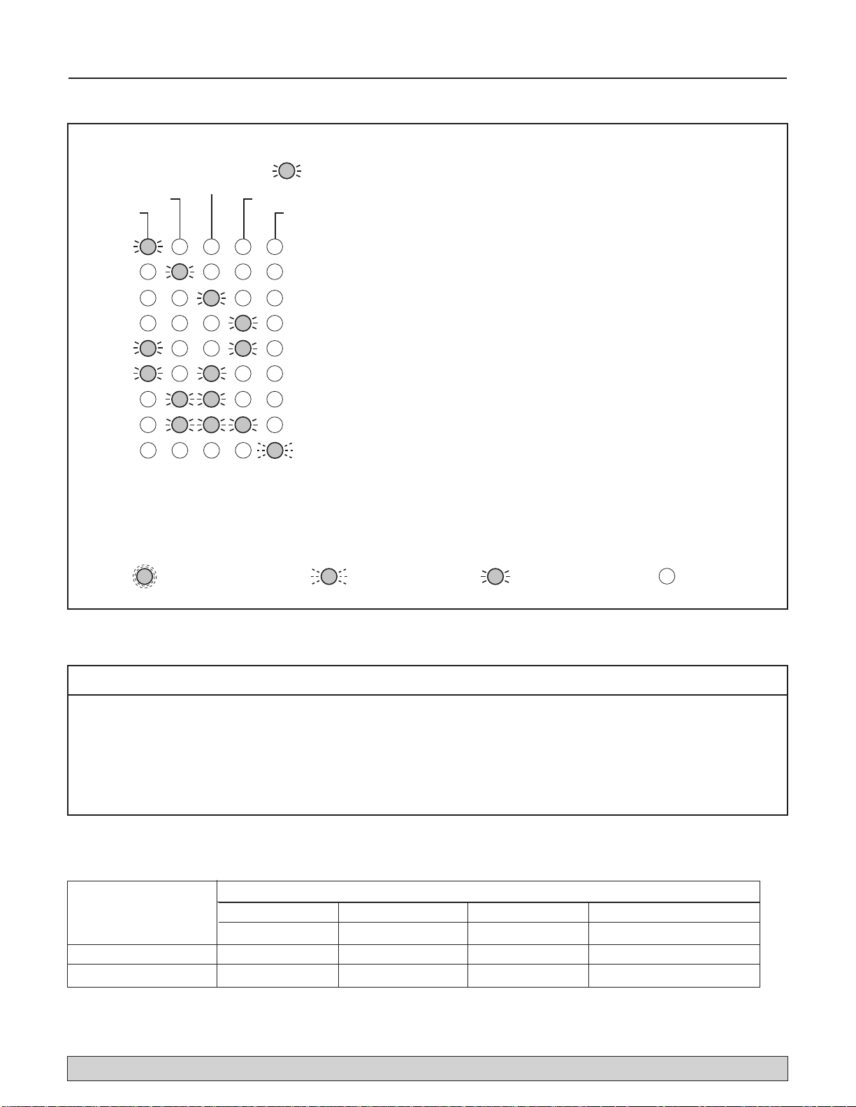
LED Display and Control Buttons
(Tables II, III, IV, and V)
NOTE: When the unit is first plugged in, or when it first
receives power from the battery, the Battery Status LED
will flash for 3 seconds.
NOTE: To activate any Control Button, depress and hold
it for 1 second.
Possible Remedies
1. Wrong Battery Voltage
Reconnect charger to a 12 volt battery.
2. Reversed Battery Connections
Check all connections. The negative (black) on the
battery must connect to the negative (black) on the
charger, and the positive on the battery must connect
to the positive on the charger. Reversing the battery
connections will cause the ‘System Alert’ and
‘Silenced Audible Alarm’ LEDs to flash.
3. Thermal Runaway Condition
“Thermal Runaway” is the technical term for the
condition of the battery when some (or all) of the
cells have deteriorated to the point that they won’t
take a charge. In this case, replace the battery.
4. Charge Time Monitor – 1 and 2
Battery took too long to complete its charge. The
‘Charge Time Monitor’ will shut down the charger
after 84 hours of continuous charging.
Possible causes are:
A) Pump ran for a long period of time during
charging, or
B) Battery is too large for the charger (including
several batteries connected in a parallel circuit).
Apply the formula in Table I to determine whether
or not your battery is too large for the charger. If the
calculated charging time is more than 84 hours, use
a smaller battery (or group of batteries).
Figure 6: Close and latch the case while holding it in
position.