flowair AURA HCS Series User guide

FLOWAIR sp. z o.o. / OMSAC210708EN
Installation and operating instruction
Air-cooled heat pumps
R410A
AURA HCS
Heat pumps

FLOWAIR sp. z o.o. / OMSAC210708EN 1
1. Introduction........................................................................................................................................................................3
Meaning of symbols ...........................................................................................................................................................3
1.1. General equipment specification...............................................................................................................................3
1.2. AURA HCS model line.................................................................................................................................................3
Use of HCS units .................................................................................................................................................................4
Basic description of the standard execution ......................................................................................................................4
Dimensions .........................................................................................................................................................................5
1.3. Used refrigerant.........................................................................................................................................................5
1.4. Legislation and security .............................................................................................................................................6
Specialized operator...........................................................................................................................................................6
Place of installation ............................................................................................................................................................7
1.5. Device identification ..................................................................................................................................................7
2. Handling and storage..........................................................................................................................................................8
2.1. Receipt of equipment ................................................................................................................................................8
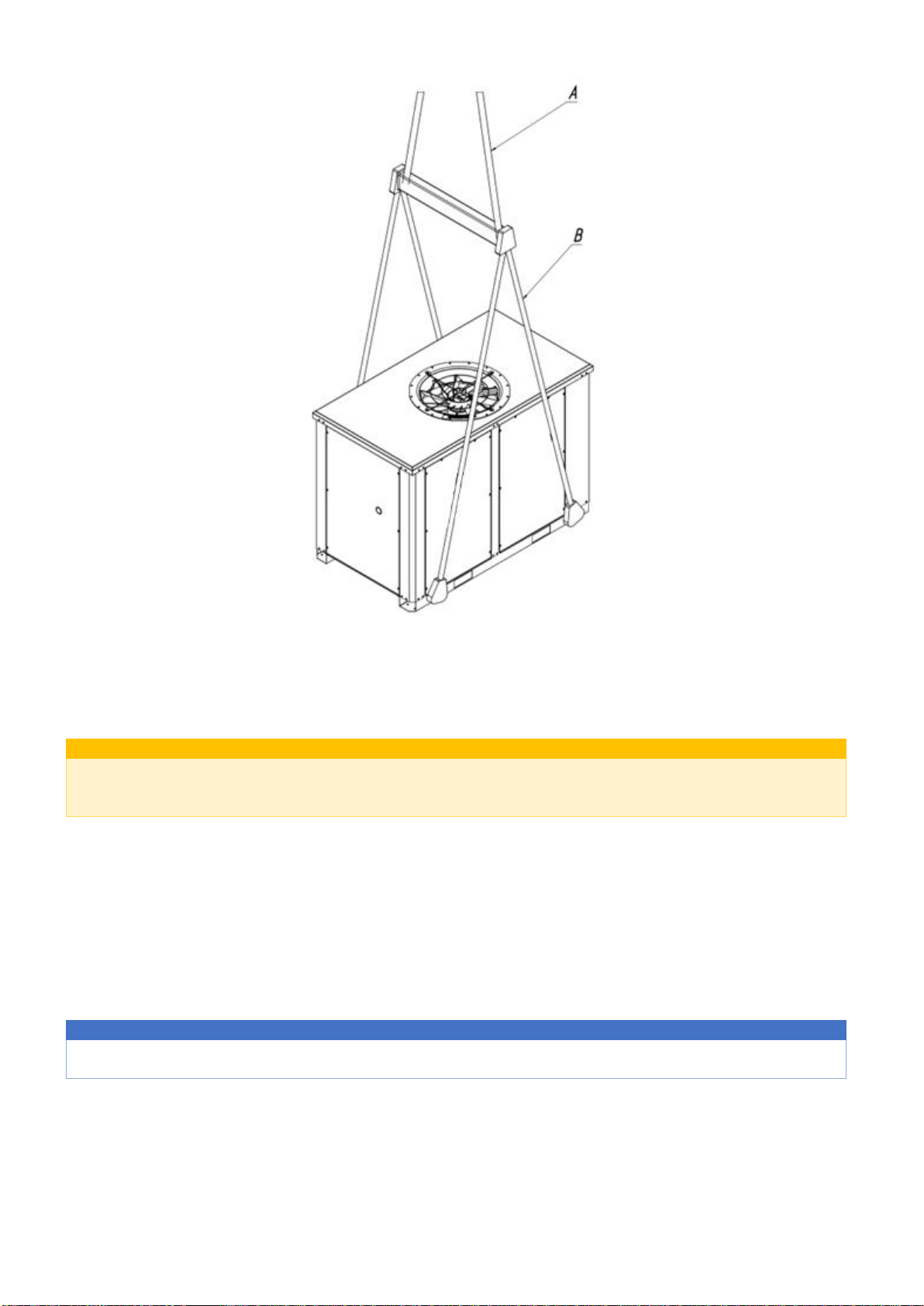
2.2. Manipulation .............................................................................................................................................................8
2.3. Storage.......................................................................................................................................................................9
3. INSTALLATION AND PREPARATION FOR COMMISSIONING..............................................................................................10
3.1. Location ...................................................................................................................................................................10
3.2. Hydraulic part ..........................................................................................................................................................12
Water treatment ..............................................................................................................................................................14
3.3. Electrical part...........................................................................................................................................................15
3.4. Cooling circuit ..........................................................................................................................................................16
4. Commissioning .................................................................................................................................................................18
4.1. Pre-commissioning inspection.................................................................................................................................18
4.2. Commissioning.........................................................................................................................................................18
Commissioning protocol...................................................................................................................................................18
Operator training..............................................................................................................................................................18
5. Operation and maintenance.............................................................................................................................................19
5.1. Principles of traffic safety ........................................................................................................................................19
5.2. Operation.................................................................................................................................................................19
Operator responsibility.....................................................................................................................................................19
5.3. Troubleshooting.......................................................................................................................................................20
5.4. Maintenance............................................................................................................................................................21
Regular service inspections ..............................................................................................................................................21
5.5. Product life cycle and disposal.................................................................................................................................22
Cooling equipment life cycle ............................................................................................................................................22
Disposal ............................................................................................................................................................................22

FLOWAIR sp. z o.o. / OMSAC210708EN 2

FLOWAIR sp. z o.o. / OMSAC210708EN 3
1. INTRODUCTION
This manual is intended for qualified operators and contains information on standard functions and operation of units of the
HCS product line, it is not intended for unprofessional personnel. Detailed information for controlling the cooling system
is given in the Manual of the ACS control system.
With the device is supplied this operating instruction and the following documents.: ACS system manual, Technical passport,
Wiring diagram, dimensional drawing, device nameplate and, if applicable, operation test protocols. In the case of different
information, the supreme documents in terms of technical specifications are documents with marked serial number of the
device (e.g. dimensional drawing with attachment points for transport).
Before installing and commissioning the device, it is essential to read the information in this manual. Improper installation
can cause very serious injuries - electric hazards, refrigerant leakage, fire, etc. or cause damage to equipment and property.
Installation work, commissioning and regular maintenance of the cooling equipment must be carried out by qualified and
trained personnel. All operations must be performed in full compliance with local laws and regulations.
If you have any questions about the documentation, contact an authorized partner or FLOWAIR service organization.
Meaning of symbols
The following types of informational alerts are used in this document:
(Other symbols of specific safety instructions are explained below)
INFORMATION
Notice of important technical information
! NOTICE !
Warning of important safety information
!!! SAFETY WARNINGS!!!
Strong warning of potential danger
1.1. General equipment specification
The air-cooled chiller or condensing unit (CU version) is intended for cooling water (possible glycol mixtures) or, in the case
of the CU version, for cooling the evaporator in air-conditioning units. The operating parameters are defined when ordering
the device and subsequently confirmed in the Technological Parameters Card (TPC) of the device.
The function of the cooling equipment is based on the heat transfer of condensation and evaporation in the cooling circuit,
which is divided into a high-pressure and a low-pressure part. The main functional parts of the device are:
Scroll type compressor, which increases the pressure of the evaporated refrigerant to the condensing pressure;
Condenser cooled by forced air flow, in which high-pressure steam condenses and thus transfers latent heat to the
surrounding air. Axial fans, fully integrated in the condenser housing, are used to ensure air flow;
Expansion valve that reduces the pressure of condensate flowing from the condenser from the condensing pressure
back to the evaporating pressure;
Evaporator in which the liquid refrigerant evaporates at low pressure and cools the water (possibly air - CU version
- condensing unit).
All cooling units are completely assembled in the factory and tested before shipment - cooling units are filled by refrigerant
and tested operationally, condensing units or coolers with a separate evaporator are tested with computer simulation.
1.2. AURA HCS model line
Water cooled units can be made with possibilities free-cooling, recuperation, reversible heat pumps or condensing units that
allow a wide range of applications

FLOWAIR sp. z o.o. / OMSAC210708EN 4
Use of HCS units
HCS cooling equipment is designed primarily for powering air conditioning systems in commercial and industrial buildings, as
well as for cooling in industrial applications. The units are a source of cooling or heating medium for secondary systems.
Basic description of the standard execution
(A detailed technical description of selected technological parts can be found later in the text of this manual.)
Operating limits
Standard design - cooling works at full load up to 0°C, with fan speed control (EC fans) and low-temperature design up to
-20°C. In the summer season, the unit operates up to 45°C. Extreme temperature protection is monitored by the ACS limiting
function. The setting of the required water temperature depends on the type of liquid used, the minimum required value for
water is 4°C (for further details see the ACS technical documentation).
The heating mode is effective down to -15°C and the water temperature is controlled by a function with restriction at very
low temperatures. The maximum set value for hot water heating is 55°C.
Condensing unit control
The CU version is externally controlled by digital or analog signals to the main controller of the unit. One or two levels of
digital control are available, depending on the number of compressors or analog control (0-10 V input) with predefined
switching levels (see ACS technical documentation for more details).
External control
Each unit can be controlled by an external on / off signal to the master controller and also sends an alarm signal to the
superior control system.
Control System
Sophisticated control system ensures data collection and subsequent control in real time, so as to ensure maximum
operational efficiency with respect to energy savings and life of technological components of the unit. The main functions of
the application are performed:
Cooling / heating power control based on measured parameters, dynamically adjusting unit power to maximize
energy efficiency.
Limitation of cooling / heating capacity in situations leading to operation at the limit of the technological possibilities
of the unit.
Three-level alarm system protects against damage caused by operation beyond the technological capabilities of the
device.
Switchboard MaR
Control panel, components and cabling manufactured in accordance with EN 60204-1. One mains connection point,
protection class IP 54, phase sequence protection and optionally heated control box. Main on / off switch installed on the
front panel, numbered and marked electrical wires for easy maintenance and service. All power components (compressors,
fans, pumps) are thermally protected.
HMI panel with protective cover or supplied for remote installation on request.
Control unit
The main microprocessor controller preconfigured during the factory test with default settings helps you get it up and running
quickly. Intuitive user interface with three levels of access - user, experienced user and technician.
The RS485 serial communication port enables remote management via ModBUS® or BacNET® control protocols. Optional
Ethernet port.
Compressors
Hermetic scroll compressors from a renowned producer with axial and radial adaptability for excellent reliability and
efficiency, equipped with crankcase heaters. Compressors with low noise and vibration levels are installed on anti-vibration
silentblocks, optionally equipped with anti-noise casings or structural covers.
Electronic discharge temperature monitoring and integrated motor thermal overload protection. Check valve on discharge.
Measuring the operating time and number of compressor starts helps to optimize the switching sequence and service
diagnostics.
Water heat exchanger
AISI 316 stainless steel plate heat exchanger, externally insulated with caoutchouc insulation is located inside the chiller
structure. The Victaulic grooved or threaded hydraulic water connection is led out of the housing of the unit.
3-step frost protection with differential pressure switch, NTC water temperature sensor and low refrigerant pressure sensor
with ACS limiting function.
Air heat exchanger with fans
Long-term reliable plate heat exchanger with aluminum fins and copper tubes, optionally equipped with a protective metal
grille.

FLOWAIR sp. z o.o. / OMSAC210708EN 5
Fans with the highest efficiency with optimized full diffuser and guide blades (meet the requirements of the ErP 2015
directive). Fan grid installed at the air outlet. The fans are fully installed inside the unit housing - flat-top, reducing noise
distribution and increasing condenser efficiency. In a flat installation, the suction point of the fan is closer to the central point
of the condenser.
Fan motor protection class F and internal temperature sensor guarantee reliability at high ambient temperatures. Fixed speed
and optionally variable speed with EC fans or voltage regulator.
Heat recovery
Partial (desuperheater) or complete heat recovery from stainless steel brazed plate heat exchangers located inside the unit
structure. The unit is equipped with an additional water heat exchanger mounted on the compressor discharge line in series
or in parallel with the air condenser. This solution makes it possible to recover up to 25% of energy with a desuperheater or
100% of condensing heat with complete recuperation. The heated water can be used for sanitary or other purposes.
Cooling circuit
Soldering of cooling circuits with a protective atmosphere performed by certified personnel. Before filling with R410A
refrigerant, each cooling circuit of the unit is subjected to a pressure test, a leak test and then evacuated.
Each cooling unit is subjected to a complete functional test to ensure operational quality.
The cooling circuit is equipped as standard with a hermetic or replaceable filter-dehydrator cartridge type, solenoid valve,
thermostatic or optionally electronic expansion valve, sight glass with humidity indicator, low pressure switch, high pressure
switch with manual reset, compressor discharge temperature sensor, high pressure and optionally low pressure sensor,
pressure relief valves according to the requirements of EN 378-2 and suction line insulation.
Depending on the version, the device is further equipped with a suction line temperature sensor, a four-way valve, non-
return valves, a collector and a liquid separator.
Hydraulic circuit
All parts of the hydraulic module are located completely inside the radiator.
Standard components of the chiller hydraulic circuit consist of NTC water inlet and outlet temperature sensors, a differential
water switch, a manometer with shut-off valves to measure the pressure difference on the evaporator.
The cooler can be optionally equipped with a centrifugal pump (static pressure available approx. 200 kPa), reserve centrifugal
pump with operating balance and automatic switching, non-return valves, shut-off ball valves, diaphragm expansion vessel
with maintenance shut-off valve, safety valve, automatic air release valve, filter strainer and drain valve. All pipes and vessels
are thermally insulated with caoutchouc insulation with closed cell structure technology.
Construction
Installing a flat top fan reduces the height of the unit and increases efficiency.
Unit housing made of galvanized sheet steel coated with polyester powder paint RAL 7035. Optional rubber or spring silent
blocks limit the transmission of vibrations to the supporting structure.
Dimensions
The table shows the basic external dimensions of the foundation frames and the total height of the HCS units.
Typoszereg
HCS
HCS
HCS
HCS
HCS
HCS
HCS
HCS
Model
113
219
325
332
444
454
563
575
Wymiary i masa
Długość [mm]
1150
1550
2000
2000
2000
2000
2200
2200
Szerokość [mm]
1000
1000
1100
1100
1100
1100
1100
1100
Wysokość [mm]
1100
1100
1400
1400
1750
1750
2180
2180
Waga [kg]
283
371
484
508
597
633
779
806
1.3. Used refrigerant
HCS units are manufactured with R410A or R134A refrigerants.
Properties R410A
HFC refrigerant - classification according to ISO 817 - A1 (non-toxic, non-flammable), GWP (global warming potential) 2 088,
critical pressure 49.2 bar, critical temperature 70.2°C. TO

FLOWAIR sp. z o.o. / OMSAC210708EN 6
Properties R134A
HFC refrigerant - classification according to ISO 817 - A1 (non-toxic, non-flammable), GWP (global warming potential) 1 430,
critical pressure 41 bar, critical temperature 101.1°C.
1.4. Legislation and security
FLOWAIR has implemented and applies a quality system for the design and manufacture of cooling and air conditioning
equipment according to ISO 9001: 2015. The design and manufacture of HCS units have been certified in accordance with
Directive 2014/68 / EU. The declaration of conformity is given in Annex No. 1 to this manual.
Basic European directives and standards related to ensuring the functionality and safety of cooling equipment:
Machine Directive (MD) 2006/42/EC
Electromagnetic Compatibility Directive (EMC) 2014/30/EU
Low Voltage Directive (LVD) 2014/35/EU
Pressure Equipment Directive (PED) 2014/68/EU
EU regulation Refrigerant Gases 517/2014
European standard for Refrigerating systems EN378 1 - 4
!!! SAFETY WARNINGS!!!
It is essential to follow all safety warnings and precautions contained in this manual. Failure to follow these rules
could result in serious injury or death.
Specialized operator
The operator must ensure the professional installation, operation, maintenance and servicing of the system by a specialist
operator if his organization does not meet the requirements of a specialist operator. The device must be installed and
connected to the electrical / hydraulic network by specialized and qualified persons. Maintenance should only be entrusted
to those companies that specialize in servicing cooling systems.
Easy maintenance of the device without opening the covers and without interfering with the system can be performed by
trained personnel. All other operations must be performed by qualified personnel. Servicing cooling systems can pose a real
risk of injury (especially high voltage and high pressure).
Specialized personnel are personnel who have the necessary equipment, facilities and experience, as well as the appropriate
qualifications for servicing and operating cooling and electrical equipment, as well as construction equipment.
!!! SAFETY WARNINGS!!!
Installation, commissioning and maintenance of cooling equipment are dangerous operations. The basic risks that
may occur when operating the equipment (EN ISO 12100 - Safety of machinery) are listed below.
High pressure is used in the system
The components of the electrical system are live - risk of injury due to contact with terminals and cables
Hot surfaces, pressurized components - there is a pipe with compressed gases in the system, there is a danger
- gushing operating media or flying objects
Sharp edges - air condensers have sharp aluminum fins
INFORMATION
Each device is equipped with a main / safety electrical switch, which can be used to safely disconnect the device from
the electrical network.
When operating the device, use protective equipment - gloves, goggles, etc..

FLOWAIR sp. z o.o. / OMSAC210708EN 7
Place of installation
The installation site provided by the operator must comply with the accident prevention regulations for the machinery (EN
294: 1992 - Safety of Machinery) and related regulations. This requirement also applies to the operation, maintenance and
service of the equipment.
1.5. Device identification
The basic identification, technical and safety parameters are listed on the nameplate located visibly on the outer frame of
the device. Basic data and explanations are given below:
WARNING!
AURA HCS is the trade name of the device. The proper identification mark for regulatory and certification purposes is the SAC
mark. The table below shows the equivalents of the designations.
Brand
Oznaczenie modelu
Aura HCS 113
SAC1-13HC-1IP4E
Aura HCS 219
SAC2-19HC-2IP4E
Aura HCS 325
SAC3-25HC-2IP3E
Aura HCS 332
SAC3-32HC-2IP4E
Aura HCS 444
SAC4-44HC-2IP3E
Aura HCS 454
SAC4-54HC-2IP4E
Aura HCS 563
SAC5-63HC-2IP3E
Aura HCS 575
SAC5-75HC-2IP4E
WATER CHILLER Cooling unit
CONDENSING UNIT Condensing unit
MODEL Model type
SERIAL N. Production identification number of the device
YEAR OF PROD. Year of Manufacture
Power supply Parameters of the electrical supply network
IP X4 Ingress protection rating
COOL Cooling mode parameters
HEAT Heating mode parameters
Pc / Ph Cooling / heating capacity
Pe Maximum electrical input
Imax Maximum allowable electric current
LRA Maximum starting current
Medium Type of cooled medium
VNominal flow rate of the cooled medium
Dp Nominal internal evaporator pressure drop
R410a Type of refrigerant
GWP Global warming potential of the refrigerant used
Cx The amount of refrigerant charge in each circuit
Net weight Weight of the device without packaging and cooled medium
PS HP / LP Maximum allowable pressure high / low pressure side
TS HP / LP (Min. / Max.) Lowest / Highest allowable temperature high / low side
MODEL
SERIAL N.
YEAR OF PROD.
IP X4
COOL
Pc /Ph
Pe
Imax
LRA
V
Dp
kg kg
kg kg
Net Weight kg
PS
Min.
Max.
Piletická 486, 503 41 Hradec Králové
MADE IN CZECH REPUBLIC
TS
(HP / LP)
°C
C4
(HP / LP)
bar
A
Medium
m3/h
kPa
WATER CHILLER
Power supply 400/3/N/PE, 50 Hz
HEAT
kW
kW
R410a GWP=2088
C1
C3
C2
A
ALPENTA s.r.o.

FLOWAIR sp. z o.o. / OMSAC210708EN 8
2. HANDLING AND STORAGE
2.1. Receipt of equipment
When transporting the device, it may be damaged by a strong shock or vibration, so the device must be inspected and, if
damage is found, photo documentation must be made to agree on further action. In case of more serious damage, it is
necessary to perform a technical inspection by an authorized partner of FLOWAIR.
! NOTICE !
The cooling equipment must be visually inspected on delivery before unloading from the vehicle. If loose or damaged
parts are found, it is necessary to contact the supplier immediately to agree on further action to resolve the situation.
The company FLOWAIR demonstrates all care to prevent damage during transport of the equipment but is not liable for
damage caused during transport of the equipment to the destination.
Immediately after unloading, check the identification data of the device stated on the nameplate (chapter Identification of
the device), and the completeness of the received documentation:
The delivery of each device includes: Technical passport, Wiring diagram, drawing with dimensions for transport mounting,
production label of the device, or protocols of the operational test. The supreme documents in terms of technical
specifications are documents with the serial number of the device (e.g. dimensional drawing with attachment points for
transport).
2.2. Manipulation
The requirements of the signs (symbols) on the packaging of the device must be observed. The basic dimensions and transport
openings and holders are shown in the drawing supplied with the device. The weight of the device is indicated on the
nameplate. Follow these rules:
Use suitable unloading / lifting equipment, lifting belts (with the capacity of the total weight of the equipment for
each belt) and other equipment.
When lifting, check the correct position of the machine's center of gravity.
Hold the device in a horizontal position. Avoid excessive rotation and tilting of the device.
The lifting gear must have adequate capacity. The weight of the device is indicated on the nameplate.
Only equipment up to a maximum total length of 3.5 m can be transported with the forklift truck. The lifting gear
(forks) must have a min. the same length as the width of the device itself. Longitudinal holes for forklift forks are
located in the devices.
The crane transports equipment with a length of more than 3.5 m, which must be lifted in accordance with the
dimensional drawing supplied with the equipment - a crane with the appropriate number of spreader bars and hinge
attachment points, which are located on the equipment frame. side).
After installing the unit at the installation site, remove the protective film and shipping fasteners.
Extreme care must be taken during transport, unloading and location of the equipment. Improper handling can damage the
device:
•Fall to the ground even from a low height
•Damage to belts and chains - without the use of spacers
•Lifting for unsuitable components
•Sudden jerk by the lifting device
•Lifting the device at an angle - overloading the suspension points
The warranty does not cover this type of damage. In the event of the above event, it is necessary to contact an authorized
FLOWAIR partner to perform a technical inspection of the equipment.
The following figure shows the basic diagram of the suspension for vertical transport of the equipment lifted by a crane at 2,
3 and 4 points of the suspension on the frame of the equipment. For standard slings, the maximum angle between the lifting
slings (marking A) is 60 ° and between the chain slings (marking B) 45°.
!!! SAFETY WARNINGS !!!
It must be ensured that no persons are present under the suspended load during transport by crane. There is a risk of
loose parts falling.

FLOWAIR sp. z o.o. / OMSAC210708EN 9
2.3. Storage
If the device is to be stored before installation, several rules for protection against damage must be observed. Storage
temperature conditions should be in the range of -25°C to +45°C at a maximum relative humidity of 95%. At high
temperatures (above 50°C) refrigerant may leak through the safety valves.
! NOTICE !
Before storing in winter, when temperatures may drop below 0°C, check that there is no water in the hydraulic circuit
and loosen the drain valves and plugs. Parts of the hydraulic circuit and subsequently the cooling circuit could be
damaged by freezing the water.
Short-term storage - within 2 months of delivery
1. Do not remove protective elements and foils
2. Protect the device from external damage - mechanical, thermal, open flame, damage by animals (e.g. rodents)
3. Protect the device from dust (e.g. from construction work)
Long-term storage - more than 2 months from delivery
1. Do not remove the protective elements, but replace the foil with another solid material - a tarpaulin
2. Protect the device from external damage - mechanical, thermal, open flame, damage by animals (e.g. rodents)
3. Protect the device from dust (e.g. from construction work)
4. Check that there is no water in the hydraulic section (see previous NOTICE)
INFORMATION
If the storage period exceeds 10 months, it is necessary to perform a complete inspection of the equipment by an
authorized FLOWAIR partner before proceeding with the installation.

FLOWAIR sp. z o.o. / OMSAC210708EN 10
3. INSTALLATION AND PREPARATION FOR COMMISSIONING
All work specified in this manual (assembly, electrical connection, commissioning, maintenance, operation, etc.) may only be
carried out by trained personnel who follow the specified procedures and the relevant local regulations. Skilled workers are
persons authorized by the manufacturer of the equipment or people who, based on their training, qualifications, experience
and personal training in training establishments, have sufficient knowledge of:
Corresponding technical standards and norms,
Occupational safety regulations and accident prevention regulations,
Laws and regulations concerning environmental protection (equipment contains F-gases),
Construction, parameters and function of the device,
Professional technical regulations for the corresponding work tasks.
3.1. Location
For the correct operation of the equipment intended for
operation in an open, usually outdoor, space, as well as its
easy operation, maintenance and repairs, it is necessary to
ensure access from each side. There should be room around
the perimeter of each device for air to flow to the condenser.
The minimum clearances are also given in the dimensional
drawing, which is part of the set of documentation supplied
with the device. Basic rules for free space around the device:
1. A minimum clearance of 1500 mm is required to
ensure airflow.
2. A minimum free space (e.g. from the switchboard) of
1200 mm is required to ensure operation.
3. The minimum distance between the condensers of
two devices placed next to each other is 3000 mm.
INFORMATION
The above dimensions are minimal to ensure functionality and basic operation. If possible, it is recommended to use,
for example, double values in the design of the installation location, taking into account the local possibilities of
airflow, prevailing wind direction and sunlight. By optimizing the location of the equipment, better energy efficiency
can be achieved as well as reduced maintenance costs (e.g. by reducing dust or dusting).
The basic rules for the location of air-cooled equipment are:
The fan directs the air vertically - into the open space. Air circulation must be prevented, hot air flowing through the
fans from the device should not be sucked back into the system and led through the condenser.
For proper operation of condensers, the device should not be installed in places with increased dust or heavy dust
(e.g. under trees).
Do not install the cooling device near heat sources - it is necessary to prevent hot air from being sucked in by the
device. Air with a temperature higher than the ambient temperature causes a decrease in the efficiency of the device
and, in extreme cases, can cause the high-pressure protection of the cooling circuit to switch on.
Do not install pipes or silencers on the air inlet or outlet. Modifications to the construction are not permitted.
Corresponding construction models of cooling equipment are used for these types of installations.
The transmission of vibrations to the connected pipe networks must be prevented. The external hydraulic circuit
must be guided in part by hoses or by using vibration compensators.
In case of installation in confined spaces, contact the manufacturer for instructions on choosing the installation
location.
If the device is freely accessible for the movement of people or animals, it is necessary to install protective grilles to
protect the device from damage.
!!! SAFETY WARNINGS !!!
If a dangerous situation has arisen despite compliance with safety regulations, the device must be disconnected from
the mains immediately. The mains cable must be secured against unintentional switching on and marked/tagged in
such a way that reconnection is not possible.

FLOWAIR sp. z o.o. / OMSAC210708EN 11
The device must be installed on a horizontal surface with a maximum deviation of 1.5 mm/m. The foundation
structure according to the approved project documentation must be solid, able to support the weight of the block
and prevent the accumulation of water.
Equipment that is located within the building structure of the building must be placed on rubber or spring silent
blocks supplied with the equipment or a professional installation company according to the type specified in the
project documentation.
When installing the device, it is first necessary to place the device with loose screws of the spring anti vibration
mounts in the pre-prepared dimensions (holes) in the base frame. The final axis of the vibromount must be in a
vertical position without tilting. The following figures illustrate the procedure.
When mounting the device on rubber silent blocks, the screws can be pre-tightened in the base frame of the device
and then placed together with the device in the final position on the base frame and then fastened. The following
figures illustrate the procedure.
The dimensions of the spring and rubber silent blocks are shown in the following figure. Together with the dimensional
drawing of the device, which shows the points for the installation of silent blocks, they allow to prepare the foundation
structure under the cooling device.

FLOWAIR sp. z o.o. / OMSAC210708EN 12
The location of the device also affects the sound pressure level around the device. If the device is installed near the
acoustically hard walls of the building, the values of the sound pressure at a distance of 10 m will be higher than the nominal
values stated in the Technical Parameters Card supplied with the device documentation. (There is a change of the Directional
factor Q = 2 –half space to Q = 4 –quarter space and thus an increase in the sound pressure level Lp independently of
maintaining the sound power level Lw of the cooling device).
3.2. Hydraulic part
The hydraulic part of the cooling equipment (except for the CU version - condensing unit) always consists of the evaporator
water circuit together with temperature sensors and flow sensor, other equipment is optional when ordering the equipment.
The technological diagram for the evaporator and recuperation circuit together with the explanations is described in the
following figures with a table.
A B C D1 D2 D3
mm 92 44 M12 98 120 130
D4 E F G H L
mm 50 150 11 393 9

FLOWAIR sp. z o.o. / OMSAC210708EN 13
The flow sensor (differential pressure) provides protection against loss of pressure / flow in the event of a pump failure or a
significant reduction in flow through an obstacle in the pipeline. In the case of using a speed-controlled pump, the minimum
flow level is defined during commissioning, especially with regard to the function of the flow sensor and, in addition, the
efficiency of heat transfer in the heat exchanger.
The device is also equipped as standard with an auxiliary contact in the motor starter of the pump, which activates the flow
alarm independently of the flow sensor when the pump is switched off.
INFORMATION
The standard control system configuration (ACS) is set so that the system checks for an open flow sensor contact
before starting the evaporator pump. (If necessary - external control of pumps without the possibility of cooperation
with the signal from the ACS, the function can be turned off in the advanced settings, but this procedure is not
recommended).
symbol
description note
ACV
accumulation vessel optional accessory, with AV and SV
AV
air-vent valve standard accessory with ACV
DV
draining valve standard accessory with ACV or EvaPum
Eva
evaporator Brazed plate or Shell&Tube heat exchanger
EvaFlo
evaporator flow switch standard accessory - differential or flow switch
EWIT
evaporator inlet water temp. sensor standard accessory - NTC sensor
EWOT
evaporator outlet water temp. sensor standard accessory - NTC sensor
EXV
expansion vessel optional accessory, equipped with SOV
PumEva
evaporator pump optional accessory, 1 or 2 pumps - 1 reserve
PumRec
recovery pump optionally supplied for external installation
Rec
recovery heat exchanger Brazed plate heat exch. For partial or full recovery
Rec3W
recovery 3W valve optionally supplied for external installation
RecFlo
recovery flow switch standard accessory with full recovery
RV
control valve optional accessory
RWIT
recovery inlet water temp. sensor standard accessory with full recovery
SOV
shut off valve optional accessory
SV
reliefe valve standard accessory with ACV, openning presure 6 bar
WG
water gauge standard accessory with PumEva or ACV
HM
hydronic module built inside of water chiller
ST
water strainer optionally supplied for external installation
VC
vibration absorber optionally supplied for external installation

FLOWAIR sp. z o.o. / OMSAC210708EN 14
EWIT and EWOT sensors are used to control the medium temperature and at the same time as protection against evaporator
freezing (more information - ACS system manual).
Filling the system
For frost protection and for the correct function of the cooling system, the system (individual parts) must be well vented
during commissioning. For proper venting of the system, it is necessary to install automatic or manual release air valves at
the highest points of the pipeline, regardless of their presence in the equipment.
The expansion vessel also includes a service valve enabling manual deaeration and disconnection of the vessel from the
system for checking the air pressure in the vessel - usually around 1.5 bar.
! NOTICE !
The minimum amount of water in the system, including the evaporator, should correspond at least to the amount of
water that flows in the system in 2 minutes. If the system does not meet this condition, it is necessary to install a
storage tank of appropriate volume in the system.
Insufficient water can affect:
•Correct function of safety elements - risk of equipment damage
•Faster wearing out of the equipment due to the risk of cavitation on the pumps as well as frequent switching on and
off of the cooling circuit
•Cooling capacity due to irregular operation
System downtime in winter
Equipment using water as a cooled medium must be protected against frost damage to parts of the hydraulic circuit when
the outside temperature drops below 4°C.
If the unit is equipped with resistance heat exchanger heating, it is necessary to check the presence of electrical supply during
the entire shutdown at low temperatures.
! NOTICE !
Before shutting down the machine in the winter, when temperatures may drop below 0°C, check that there is no
water in the hydraulic circuit and loosen the drain valves and plugs or fill the system with antifreeze. Freezing water
could damage the device.
External part of the hydraulic circuit
The connection of the pipeline network to the equipment, its setting and installation must comply with current legal
regulations, technical requirements and requirements for maximum safety. In addition, following the instructions below will
prevent damage to the device:
Avoid unnecessary pressure losses, ensure correct circuit size and tracing.
The connecting pipe must be fastened to a separate supporting structure so that it does not burden the assembled
joints.
Connect expansion joints to the device to prevent noise and vibration.
Install shut-off and drain valves on the outside of the unit so that you can shut down and drain the system for
maintenance and service.
Install the drain valve at the lowest points of the water circuit and the vent valve at the highest points of the circuit.
Install a particulate filter at the inlet to the unit to prevent possible freezing and damage to the evaporator.
Mount a thermometer and manometer on the inlet and outlet of each heat exchanger for quick inspection and
maintenance.
Hydraulic piping must be insulated to prevent condensation and thus loss of performance. Pipe insulation is only
performed after checking the complete system under pressure.
Water treatment
The quality and purity of the refrigerated medium play a crucial role in the trouble-free and energy-efficient operation of the
cooling equipment.
! NOTICE !
The cleanable strainer filter must be installed at the liquid inlet to the evaporator (possibly recuperation), which
removes impurities before entering the exchanger. Install a cleaning filter at least 1 000 mm before connecting the
evaporator and after all welds (there are no welds between the filter and the evaporator). The filter should have holes
no larger than 1.5 mm for models with a plate evaporator or 3.0 mm for a tube evaporator.

FLOWAIR sp. z o.o. / OMSAC210708EN 15
INFORMATION
It is recommended to flush the piping system after its completion by bypassing the cooling equipment.
INFORMATION
To prolong the life of the components, we recommend the use of additives for antifreeze mixtures, so-called corrosion
inhibitors.
Glycol mixtures
V případě použití glykolových směsí:
The freezing point of glycol must be lower than the minimum evaporation temperature
The concentration of the mixture should not be higher than the calculated one stated on the nameplate, otherwise
the cooling capacity of the system will be reduced
Check the pH of the mixture, which should be approximately between 9.5 - 8
Check the pH value regularly (during maintenance)
In the case of an external hydromodule, make sure that the pump used and other circuit elements and seals are
suitable for working with refrigerated media (when using glycol).
! NOTICE !
It is not permissible to discharge a mixture of water and glycol into the sewer. Mixture Must be collected in special
packaging and disposed of in accordance with waste disposal regulations.
3.3. Electrical part
The equipment documentation also includes an electrical wiring diagram and the ACS System Manual, which is used to control
all functions of the cooling equipment.
The mains voltage and frequency must correspond to the values on the rating plate of the appliance. The supply voltage
should not exceed the values given in the wiring diagram for a short time, which is +/- 5% for the voltage; +/- 1% for frequency,
unless otherwise stated.
The supply cables must be adequately fused and dimensioned to correspond to the electrical performance characteristics
specified on the nameplate and the supplied electrical specifications in the wiring diagram.
The protective earth conductor, which interconnects the protective conductor, the earth lead and the conductive parts, must
comply with standard EN 60204-1. The connecting cable (earthed) must have a cross section of at least 10 mm2.
! NOTICE !
It is not permissible to mechanically load the supply terminals of the electrical switchboard.
!!! SAFETY WARNING !!!
The electrical connection must be carried out by qualified personnel in accordance with the local regulations in force.
There is a risk of electric shock.
Before connecting the equipment or servicing electrical parts, make sure that the main / safety switch is in the OFF position.
! NOTICE !
The system operator must ensure that the power supply is equipped with a disconnector, e.g. a mains switch with an
appropriate contact rating, and that the mains supply must also be equipped with a separate fuse and an emergency
switch. (all dimensioned according to the relevant approved project documentation of the electrical installation).

FLOWAIR sp. z o.o. / OMSAC210708EN 16
Detailed information on individual inputs
/ outputs and control unit configuration is
given in the ACS Control System Manual.
The table shows the basic parts of the
external electrical connection of cooling
equipment for electrical installation.
Detailed information and wiring diagram
are supplied with the device.
A - Power connection - power
supply from the network 400/3 /
N / PE, 50Hz
B - External control - ExtOn signal
for remote start, AlmExt signal
for information about the alarm status of the cooling device (can be configured in the ACS system)
C - ModBUS - connection for ModBUS communication via RS485, optionally Ethernet
D - DCU - digital switching of cooling capacity for versions U - condensing unit
E-ACU - analog control of cooling capacity for versions U - condensing unit
3.4. Cooling circuit
HCS cooling units can have 1 cooling circuit with 1 to 3 compressors as standard.
Soldering of cooling circuits with a protective atmosphere performed by certified personnel. Before filling with refrigerant,
each cooling circuit of the unit is subjected to a pressure test, a leak test and then evacuated.
Each cooling unit is subjected to a complete functional test or a functional test by means of a computer simulation
(condensing unit type CU or condenser with a remote evaporator).
The cooling circuit is equipped as standard:
hermetic or replaceable cartridge type filter-dehydrator,
solenoid valve, (CU version - included)
thermostatic or optionally electronic expansion valve, (CU version - included)
sight glass with humidity indicator, (CU version - included)
low pressure switch,
high pressure switch with manual reset,
temperature sensor on the compressor discharge,
high-pressure and optionally low-pressure sensor,
shut-off valve before entering the condenser,
safety valves for pressure relief according to the requirements of EN 378-2 and suction line insulation.
Depending on the version, the device is further equipped with a suction line temperature sensor, a four-way valve, non-
return valves, a collector and a liquid separator.
In preparation for commissioning, it is necessary to check whether the equipment has not been damaged or there has been
no refrigerant leakage:
•Visually complete and potential for unwanted mechanical damage to the cooling circuit elements
•Potential refrigerant / oil leak - visually, by leak detector or bubble method
•Tighten screw connections, especially oil lines, manometer nuts and service valves
•The refrigerant pressure in the idle state of the device must correspond to the ambient air temperature on the high
pressure side - the pressure can be checked on the device monometers (optional equipment), by connecting a
service manometer or on the control unit
The following is the basic technological single-circuit diagram of the cooling circuit together with a table of abbreviations
used and explanations.

FLOWAIR sp. z o.o. / OMSAC210708EN 17
symbol
description note
CCH
compressor crankcase heater heating when the compressor is off
Com
compressor Scroll compressor
Con
condenser Cu pipes and Al fins coil
DsT
discharge temp. sensor discharge high temperature protection
Eva
evaporator brazed plate or shell&tube heat exchanger
Fan
fan axial fan with full nozzle
FLT
filter dryer filter drier with a replaceable cartridge
HGBp
hot gas by-pass optional accessory
HPG
high pressure gauge optionall accessory
HPS
high pressure switch safety pressure switch with manual reset PZH (EN 12263)
HPT
high pressure transducer condensation control and high pressure limitation
LBp
liquid bypass optional accessory
LIQ
sight glass sight glass with moisture indicator
LPG
low pressure gauge optionall accessory
LPS
low pressure switch low pressure protection with automatic reset PSL (EN12263)
LPT
low pressure transducer optional accessory, low pressure limitation
LR
liquid receiver optional accessory
OAT
temperature sensor sensor NTC
OIL
oil equalization compressor oil equalization with sight glass level indication
Rec
recovery exchanger plate desuperheater or full recovery
ROT
rotalock valve optional accessory
SFV
safety valve pressure relief valve EN 378-2 and EN 13136
SOL
solenoid valve installed together with thermostatic expansion valve
SOV
shutt off valve installed on discharge line or as an option
SV
service valve Schrader 1/4" SAE
TEV
thermostatic expansion valve optionally electronic expansion valve

FLOWAIR sp. z o.o. / OMSAC210708EN 18
4. COMMISSIONING
4.1. Pre-commissioning inspection
Before commissioning the device, it is necessary to check the device and related installations. The basic control activities are
listed in the Pre-commissioning inspection protocol (appendix).
Check that the minimum distances are maintained for the correct operation of the device and that the necessary maintenance
space is available.
Find out if the device has been damaged or subsequently modified without the manufacturer's authorization, for example by
incorrect installation of cable trays or pipes (e.g. they may impede service access or air flow, etc.). There must be no screws
or other sharp objects near the condensers that could cause mechanical damage to the heat exchanger due to vibration.
It is recommended to obtain photo documentation from the installation site before putting the device into operation.
! NOTICE !
Before switching on the device for the first time or after a longer shutdown, the compressor oil must be warmed up.
The crankcase is heated by heating cables at least 12 hours before switching on. To start heating, turn the main switch
to the ON position. The crankcase heating function is automatically active when the main switch is in the (ON
position).
4.2. Commissioning
The commissioning of the equipment may follow a previous inspection of the entire system (Pre-commissioning inspection)
in a situation where the subsequent cooled (heated) heated system can be loaded to at least 60% of the equipment output.
In the case of reversible coolers, it is possible to put the device into operation in both modes during the transitional period,
otherwise the commissioning process must be completed under suitable conditions.
A detailed description of operating sequences, modes, parameters and alarm messages is given in the ACS Control System
Manual. It can be used during commissioning:
Variable speed fan and pump test modes
Possibility of manual shutdown of selected compressors during commissioning
Temporary setting of the desired water temperatures for accelerating / decelerating the operating sequence
Temporarily switch off the flow control before starting the device (e.g. during external pump control)
Commissioning protocol
The commissioning report should contain information on the operating parameters at the first start-up, identification of the
equipment, name and confirmation of the qualified service and confirmation of the commissioning customer - a sample is
given in the appendix.
The completed Commissioning Protocol is a condition of warranty performance in the event of a device complaint.
Operator training
The operator of the cooling system must be trained during commissioning, ie before the formal commissioning, which begins
with the signing of the Commissioning Protocol (Annex).
As part of the operator training, the future operator will get acquainted mainly with:
•Safety rules for operating cooling equipment
•Basic tasks of user operation and weekly inspections (chapter maintenance)
•Basic operating sequence
•Temperature and pressure safety elements
•Basics of wiring and safety elements
•Operation of the control unit and setting of basic parameters
•Alarm states and possibilities of their solution
•Documentation for cooling equipment - Operating instructions for the equipment and control system, Wiring
diagram
•Obligation to keep operational documentation and protocols (appendix)

FLOWAIR sp. z o.o. / OMSAC210708EN 19
5. OPERATION AND MAINTENANCE
5.1. Principles of traffic safety
Before carrying out any service work, it is necessary to familiarize yourself with safety regulations and measures.
The operator must always be equipped with personal protective equipment that corresponds to the work performed.
Personal aids generally include in particular: goggles, gloves, headgear or helmet, protective work footwear. Additional
protective equipment must be selected after performing a risk analysis in the appropriate area, according to the type of work
performed.
5.2. Operation
Operator responsibility
The operator of the cooling equipment is obliged to provide qualified personnel familiar with the characteristics of the
installed equipment. From the point of view of basic information about the device, it is a thorough acquaintance with the
instructions for the device (especially this manual and the ACS manual) and the operator is obliged to keep the documentation
necessary for the operation of the device:
1. Pre-commissioning inspection report, Commissioning report (model in annex)
2. Cooling equipment inspection book (see NOTICE below)
3. Service book or Service maintenance protocols (sample in the appendix) - records from maintenance and service
interventions (contains date, description of the action, if necessary, with measured parameters and confirmation of
a qualified person performing service intervention)
In the event that the operator detects unusual operating conditions or equipment failure, it is recommended to contact an
authorized FLOWAIR partner to agree on further action.
! NOTICE !
According to Regulation (EU) 517/2014 of the European Parliament and of the Council on fluorinated greenhouse
gases: The operator of an installation that contains F-gases in an amount of more than 5 tonnes of CO2 equivalent is
required by law to ensure regular leak tests. Inspections may only be performed by certified persons holding a
category I certificate (EU Implementing Regulation 2015/2067).
Risk of fatal injury. Disconnect the device from the power supply before opening the electrical
switchboard or removing the protective panels. When the main switch is disconnected, the supply
contacts L1, L2 and L3 remain energized.
Danger of burns, pipes can reach high temperatures
Risk of frostbite. Do not remove any parts of the cooling circuit piping before depressurizing the system
Wear safety goggles and rubber gloves when handling refrigerants.
Danger of suffocation. Ventilate the area when working with refrigerant gases. Smoking is strictly
forbidden.
It is forbidden to discharge refrigerant into the environment. It must be collected in bottles and reused or
returned to a specialized company.
Risk of injury. If fan maintenance is required, prevent body parts or clothing from entering moving parts .
Insurance devices. It is forbidden to switch off or interfere with the operation of safety devices, such as
flow switches, pressure sensors, safety valves, etc.
Changes to the software or electrical system may only be made after consultation with the
manufacturer. Any wiring changes must be made according to the wiring diagram.
This manual suits for next models
8
Table of contents
Popular Heat Pump manuals by other brands

CIAT
CIAT YUNA II installation manual

Viessmann
Viessmann VITOCAL 350-A operating instructions

Kensa Heat Pumps
Kensa Heat Pumps 7kW Evo Installation and commissioning manual

Bryant
Bryant LEGACY 223A installation instructions

Walter Roller
Walter Roller Silent Line WPV Mounting instructions

LG
LG ARNU07GSEL1 manual

GRE
GRE BC3800 instruction manual

Econar
Econar GeoSource DualTEK GV Series Installation and operating instructions

Haier
Haier AW052MUCHA installation manual

Carrier
Carrier Gemini 38AU 07 Series Installation, Start-Up and Service Instructions

UL
UL BADF090 Installation instruction

Sanyo
Sanyo ECO-i APR-CHP680BA Submittal data