FLOWTECH flowpress User manual

1
First Publication Date: 01/09/2020
Revision:
Revision Date:
OPERATION AND
MAINTENANCE MANUAL
DS Pressurisation & Dosing Units

Contents
General Information 3
Safety Information 4
Equipment Overview 7
Principal of Operation 7
Installation 8
Typical Installation Diagram 8
Electrical Power Supply 10
Micro Controller 11
Fault contacts 11
Commissioning 12
Controller Overview 13
Controller Programming 14
Program List 15
Hydraulic Commissioning 18
Balancing Valve Seing 21
Open and Close 21
Seing the Flow 21
Notes 21
Operation 23
Fault Codes 23
Shutdown procedure 24
Start-up Procedure 24
Maintenance 25
Wiring diagram 27
Spare Parts 29
FlowpressDS Models 30
Troubleshooting 31
Warranty Details 34
Conditions of warranty 34
2

Definitions of Safety Warnings and
Precautions
WARNING!
Indicates a potentially hazardous situation which, if
not avoided, can result in serious injury or death.
CAUTION!
Indicates a potentially hazardous situation which, if
not avoided. Can result in minor to moderate injury, or
serious damage to the product.
General
Information
These instructions are to assist in the installation of the flowpress DS Pressurisation Units
please follow them carefully.
If, having read this Operation & Maintenance Manual, there is any doubt about any aspect of
the installation please don't hesitate to contact our technical team.
flowpress DS Pressurisation & Dosing Units
3

Safety
Information
It is essential that correct and safe working practices are adhered to at all times when installing,
operating and/or maintaining any piece of equipment. Always consult safety data sheets, operating
and maintenance manuals, Health & Safety legislation and recommendations and specific
requirements of any equipment manufacturer, site controller, building manager or any other persons
or organisation relating to the procurement, installation, operation and/or maintenance of any piece
of equipment associated or in conjunction with any product provided by flowech Water Solutions.
This document is intended for ALL installers, operators, users and persons carrying out maintenance
of this equipment and must be kept with the equipment, for the life of the equipment and made
available to all persons at all times. Prior to carrying out any work associated with the set it is essential
that the following sheets are read, fully understood and adhered to at all times.
Equipment must only be installed, operated, used, and/or maintained by a competent person. A
competent person is someone who is technically competent and familiar with all safety practices
and all of the hazards involved.
Any damage caused to any equipment by misapplication, mishandling or misuse could lead to risk of
Electrocution, Burns, Fire, Flooding, death or injury to people and/or damage to property dependent
upon the circumstances involved. flowech Water Solutions accepts no responsibility or liability for
any damage, losses, injury, fatalities or consequences of any kind due to misapplication, mishandling
or misuse of any equipment, or as a result of failure to comply with this manual.
Failure to install, operate, use or maintain the equipment in accordance with the information contained
within this document could cause damage to the equipment and any other equipment subsequently
connected to it, invalidating any warranties provided by flowech Water Solutions to the buyer.
4

SAFETY WARNINGS &
PRECAUTIONS
These instructions should be read and clearly understood before working on the system. Please
read this manual carefully and all of the warning signs aached before installing or operating the
equipment keep this manual handy for your reference. This equipment should be installed, adjusted
and serviced by trained and qualified personnel. Failure to observe this precaution could result in
bodily injury.
WARNING! - Install an emergency stop key separately from the isolator. Rotating
shas can be hazardous.
WARNING! - This equipment has a high leakage current and must be permanently
fixed to earth.
WARNING! - Do not aach or remove wiring or connectors when the power is applied.
Do not check signals during operation. When the power is turned on and the running
command is on, the motor will start rotating. The stop key is only eective when the
function is set. If there is a power failure and an operation instruction is given the unit
may start automatically when the power is reinstated.
WARNING! - Make sure that the input voltage is correct. Be sure to install the unit in
a room that is not exposed to direct sunlight and is well ventilated.
Avoid environments which have a high ambient temperature, high humidity or
excessive condensation. Avoid dust. Corrosive gas, explosive gas, inflammable gas,
grinding-fluid mist and salt damage, etc.
WARNING! - Do not connect the power source to any terminals except power
connectors.
WARNING! - Motor control equipment and electronic controllers are connected to
hazardous line voltages. When servicing drives and electronic controllers, you may be
exposed to components at or above the line potential. Extreme care should he taken
to protect against shock. Dangerous voltage may exist aer the power light is o.
Wait more than 5 minutes aer turning o the power supply before performing
maintenance or inspection. Hazard of electric shock. Disconnect incoming power
before working on this unit.
WARNING! - The inverter should be protected separately against ground fault.
Observe the regional regulations for electrical installation!
flowpress DS Pressurisation & Dosing Units
5

CUSTOMER / CONTRACTOR
RESPONSIBILITIES
It is the responsibility of the customer and/or the contractor:
• To ensure that anyone working on the equipment is wearing all necessary protective gear
and/or clothing.
• Is aware of appropriate health & safety warnings.
• Has read the information in this section of the manual.
CAUTION! - It is strongly recommended that all electrical equipment conforms
to National Electrical Codes and local regulations. Only qualified personnel should
perform installation, alignment and maintenance. The manufacturer reserves the right
to alter the technical data in order to make improvements or update information.
CAUTION! - Failure to observe these rules will render the guarantee invalid. The same
applies to repair jobs and/or replacement. Your legal rights are not aected.
CAUTION! - The manufacturer declines all responsibility in the event of damage or
injury caused as a result of tampering with the equipment.
CAUTION! - Do not switch on/o power supply to run/stop the motor/system! Start
the unit only by using run buon or external run command.
We strongly recommend that commissioning and service
work is carried out by the manufacturer’s personnel or
appointed agents ~ please contact our technical sales
department for information on our commissioning and
service contract packages.
6

Equipment Overview
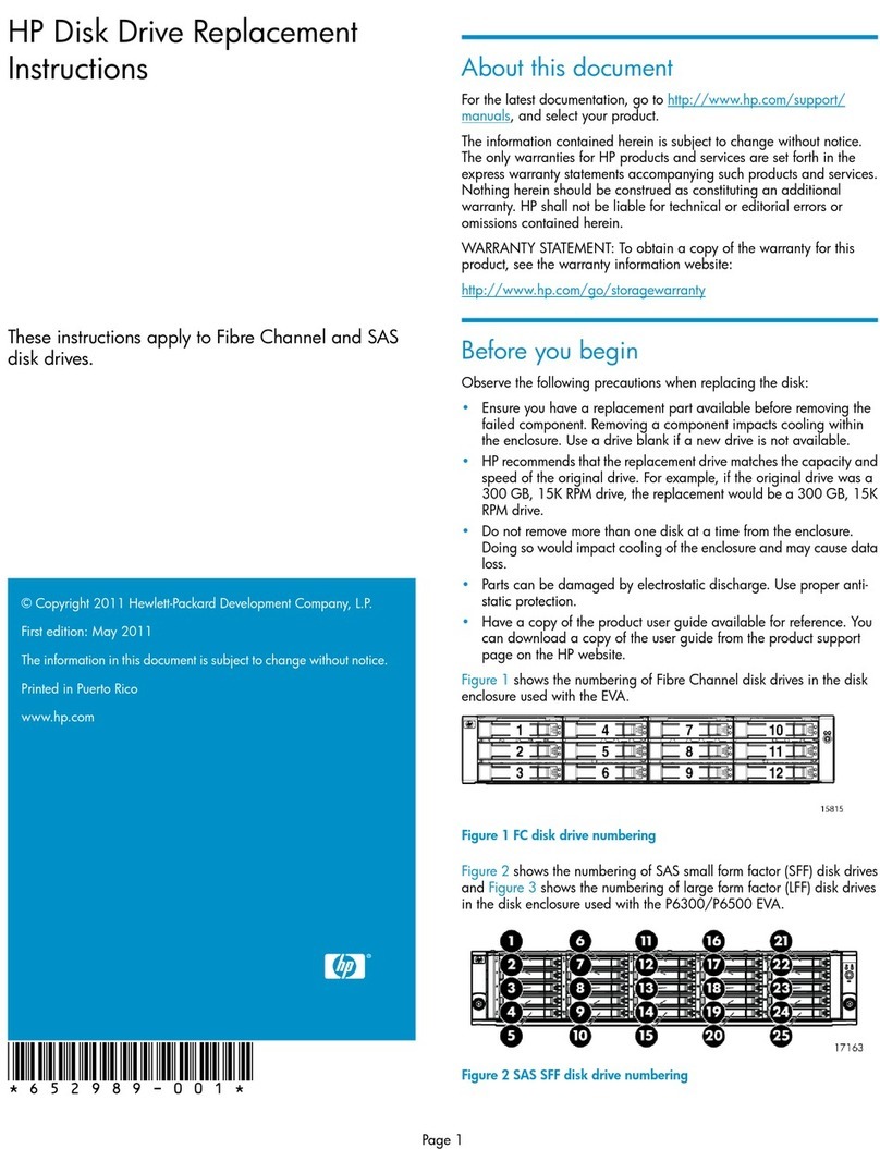
The function of this pressurisation unit is to provide a means of automated water top-up to sealed heating
and cooling systems. The equipment is designed to provide periodic water top-up to compensate for minor
losses insystem pressure (e.g. slow leaks, air venting, etc.).
This equipment is not designed to cope with sudden losses of system pressure (e.g. manual draining) or ma-
jor water losses (e.g. large leaks). The equipment is also not intended to be used for water boosting applica-
tions.
Principal of Operation
The following schematic shows the internal arrangement of a pressurisation unit:
The flowpress DS unit is fied with a break tank (1) which is filled from the mains water supply (2) via
a float operated valve (3). The break tank is fied with an overflow (4) in case the break tank overfills,
and a weir overflow (5) in case the primary overflow fails. Also fied is an additive tank (14). Additive
tank is filled with either glycol or additive, to add to the system a required mixture is required. To do
this two balancing valves areplaced aer each of the tanks to control the mixture water (12) and
Glycol (13). (See mixture table)
The pressurisation unit is connected into the heating system (6) via an isolation valve (7).
The pressure sensor (8) monitors the system pressure.
If the pressure sensor detects a drop in pressure, the pump (9a) will pump water from the break
tank into thesystem. Once the required pressure has been reached, the pump will stop.
On twin pump models, a second pump (9b) is provided. The two pumps will run in a duty/standby
configuration(i.e. the active pump will alternate with each pump start).
The pump(s) are fied with non-return valves (10a, 10b) to prevent backflow.
A drain valve (11) is provided for draining down the unit and for commissioning purposes.
flowpress DS Pressurisation & Dosing Units
7

Installation
This pressurisation unit is not designed to be installed in an outdoor environment. The unit must be
installed in a frost free environment, away from precipitation and water sprays/jets. If there isa risk of
flooding, the unit must be installed on a raised plinth.
Please refer to the appropriate datasheet for the maximum working pressure and temperature ofthe
pressurisation unit. The conditions at the point of connection to the system must not exceed these
values.
Pipe Connections
To avoid damaging the float valve, the mains water supply pipe must be flushed before connection to the
pressurisation unit.
All pipe connections must be made with appropriate jointing compound/PTFE tape.
If PTFE tape is used, care must be taken to ensure that the tape does not obstruct the orifice of the fiing.
Non-return valves, pressure reducing valves and RPZ valves must not be installed between the pressurisation
unit and the heating/cooling system. These devices will prevent the pressure sensor from reading the system
pressure.
The pressurisation unit and expansion vessel should be connected to the system at the same point, to provide
a neutral pressure reading. This point of connection should be in the systemreturn, on the suction side of the
circulation pump.
Typical Installation Diagram
8

Flowpress DS Clearance and Connection Requirements
Connection Size Notes
Mains Water
Feed
½” BSP M An isolation valve must be installed
on the mains water feed for
servicing.
Break Tank
Overflow
22mm Guidance on drainage
requirements should be obtained
from the local water authority.
System Con-
nection
½” BSP M
/ 15mm
The pressurisation unit and
expansion vessel should be
connected to the system at the
same point.
The point of connection shouldbe
in the system return, on thesuction
side of the circulation pump.
Non-return valves, pressure
reducing valves and RPZ valves
must not be used.
flowpress DS Pressurisation & Dosing Units
9

Electrical Power Supply
This equipment must be electrically isolated before removing the covers. Cables connected to the
volt free contacts may be supplied from another source and may remain live aer the unit is isolated.
These must be isolated elsewhere.
All electrical connections must be carried out by a suitably qualified and competent person.
The mains power supply to the pressurisation unit must be connected into the fused terminal
block as shownbelow:
On some larger models, the fused terminal block is replaced by a fused spur. If this is the case, the
power supplymust be connected into the fused spur, as shown below:
It is recommended to supply power to the pressurisation unit via a lockable isolator. This should be
installed within 2m of the equipment.
This equipment can be damaged by the high voltages produced by electrical installation testing
equipment. When performing electrical installation tests, the equipment must be isolated from the
supply.
10

Micro Controller
Fault contacts
There are 6 volt free fault contacts which can be used for connection to a BMS system, or as a
boiler interlock.These are terminals 1-12, located on the digital controller:
With the exception of the Common Alarm, it is possible to convert all other fault contacts to normally
closed. For further information please refer to the commissioning section of this manual.
flowpress DS Pressurisation & Dosing Units
11

Commissioning
It is highly recommended to have this equipment commissioned by a Flowtech approved engineer.
Any damage or loss incurred through incorrect commissioning by an unapproved engineer will not be
covered by the warranty.
Pre-Commissioning Checklist
The following conditions must be met before starting the commissioning process. Failure to meetthese
conditions may result in injury or damage to the equipment, system and property.
Equipment is sited in a frost free area, away from precipitation and water sprays/jets
All necessary pipe/electrical connections have been made to a satisfactory standard
The temperature and pressure at the point of connection are within the operating limits of the pressurisation
unit.
The heating/cooling system is fied with a safety valve and expansion vessel
The following conditions must be met for the pressurisation unit and heating/cooling system to function
correctly. If these conditions have not been met, it is not advisable to proceed with thecommissioning process.
The system connection has been made into the system return header/pump suction
There are no non-return valves, pressure reducing valves or RPZ valves installed between the pressurisation
unit and the heating/cooling system
The expansion vessel is pre-charged to the correct pressure (equal to fill pressure)
It is advisable to fill the heating/cooling system prior to commissioning. If this is not possible, the pressurisation
unit can be used to fill the system aer commissioning. Depending on the size of the system, this may take a
considerable amount of time.
The heating/cooling system is filled and pressurised to the required cold fill pressure, with the water at
ambient temperature (approximately).
12

Controller Overview
The following image shows the front of the pressurisation unit digital controller. 4 buons are
provided forprogramming, and an LED display which shows scrolling messages.
When the controller is first powered up, it will display the controller version number. This manual
relates to controller version >8.0. If the controller is of a dierent version, there may be dierences in
the menu items available.
When in normal operation, the controller will display the current system pressure. If a fault
occurs, thecontroller will display a fault code and produce an audible alarm.
In normal operation, the functions of the buons are as follows:
Buon Function
Press Hold
SET -Show Current System Pres-
sure
MUTE Mute Audible
Alarm
Reset Unit
+-Enter Programming Menu
--Enter Programming Menu
flowpress DS Pressurisation & Dosing Units
13

Controller Programming
Do not alter any seings without first understanding the implications of doing so. Incorrect
seings may cause damage to the equipment, system or property.
To enter the programming menu, hold the (+) buon until “enter code” appears on the screen,
followed by“0000” with a flashing cursor aer the first digit.
To gain access to the programming menu, one of the following codes must be entered:
Customer Code Standard set of options 2601
To enter the code, change the first digit with the (+) and (-) buons, then press (SET) to move
onto the nextdigit. Repeat for all digits, then once the correct code is shown on the display, press
(SET) to enter the programming menu.
Once a correct code has been entered, the first option [COLD FILL] will appear on the screen.
Once in the menu, the value of the current menu item can be changed using the (+) and (-)
buons. Once thecurrent value has been set, pressing the (SET) buon will move on to the next
option.
It is not possible to navigate backwards through the menu. To return to a previous seing in the
menu, press the (SET) buon repeatedly to scroll through to the end of the menu, and then re-
enter the appropriate code.
If the controller looses power while in the programming menu, all changes made will be erased. To
confirm all changes, the end of the menu must be reached, and the “SAVING...” message mustbe
displayed.
14

Program List
The table below gives details of all menu items, in the order that they will appear:
#Menu Item Function Default
Value
1COLD FILL
The required fill pressure, i.e. pump ‘cut-out’ pressure.
The recommended seing is 0.3 BAR above the static pressure of the
system(0.1 Bar per meter of static height).
For example, a 14m high installation will have a static pressure of 1.4 Bar,
making the recommended cold fill pressure 1.7 Bar.
It is not possible to enter a value higher than the current [HIGH SET] or lower
than the current [LOW SET] values.
1.0 Bar
2HIGH SET
The high pressure alarm seing.
If the pressure in the system reaches this value, the <HIGH PRESSURE>
alarmand common alarm will be activated.
The recommended seing is 10% below the safety valve rating.
For example, if the safety valve rating is 3 Bar, the recommended seing is
2.7Bar.
It is not possible to enter a value lower than the current [COLD FILL] value.
2.7 Bar
3LOW SET
The low pressure alarm seing.
If the pressure in the system falls below this value, the <LOW PRESSURE>
alarm and common alarm will be activated, and the pressurisation pumps
willnot run.
The recommended seing is 0.5 Bar below the [COLD FILL] pressure.
It is not possible to enter a value higher than the current [COLD FILL] value.
0.5 Bar
4 DIFFERENTIAL
The dierential between the ‘cut-in’ and ‘cut-out’ pressures of the
pressurisation pumps.
The cut-in pressure will be equal to the [COLD FILL] pressure, minus
thedierential pressure.
For example, if the [COLD FILL] pressure is set to 1.5 bar, and the dierential
set to 0.2 Bar, the pump ‘cut-in’ pressure will be 1.3 Bar (1.5 – 0.2 = 1.3)
0.2 Bar
5FLOOD LIMIT
The maximum continuous run time for each of the pressurisation pumps.
If a pump runs continuously for longer than this period, the pump will
stopand a <FLOOD LIMIT> alarm will be activated.
This is to prevent the unit from pumping large amounts of water in the event
of a large leak/burst pipe.
For very large systems, this may need to be increased.
The value can be changed in increments of 10 minutes, to a maximum of 990.
10 MINS
6PUMP 1 COUNT
The cumulative number of pump starts for pump 1.
This is a cumulative counter, the value of which cannot be modified. If using
the engineer’s code, the counter can be reset to zero by holding the (MUTE)
buon.
-
7PUMP 1 HOURS
The cumulative run time in hours for pump 1.
This is a cumulative timer, the value of which cannot be modified. If using the
engineer’s code, the counter can be reset to zero by holding the (MUTE)
buon.
-
flowpress DS Pressurisation & Dosing Units
15

#Menu Item Function Default
Value
8PUMP 2 COUNT
The cumulative number of pump starts for pump 2.
This is a cumulative counter, the value of which cannot be modified. If
using theengineer’s code, the counter can be reset to zero by holding the
(MUTE) buon.
-
9PUMP 2 HOURS
The cumulative run time in hours for pump 2.
This is a cumulative timer, the value of which cannot be modified. If using
the
engineer’s code, the counter can be reset to zero by holding the (MUTE)
buon.
-
10 ALARM COUNT
The cumulative number of all alarm incidents.
This is a cumulative counter, the value of which cannot be modified. If
using theengineer’s code, the counter can be reset to zero by holding the
(MUTE) buon.
-
11
POWER
INTERRUPTED
The cumulative number of power interruptions (i.e. controller turned
o/power cut).
This is a cumulative counter, the value of which cannot be modified. If
using theengineer’s code, the counter can be reset to zero by holding the
(MUTE) buon.
-
12 PULSE
When enabled, if a pump has been inactive for 60 days, it will start and
run for2 seconds.
This is to prevent the pumps from seizing.
YES
13
EXCESSIVE
START
When enabled, if there are more than 3 individual pump runs within an 8
hourperiod, the unit will register an <EXCESSIVE DEMAND> alarm.
Enabling this option may cause false alarms on some systems.
NO
14 SERVICE
When enabled, a service reminder will be displayed aer 12 months from
whenthe option was enabled.
To reset the service reminder, set the value to ‘NO’ and exit the menu.
Then,re-enter the menu and set the value to ‘YES’ again.
NO
15 FILL SYSTEM
When enabled, the <LOW PRESSURE> and <FLOOD LIMIT> alarms will
be disabled, and pump 1 will run continuously for up to 24 hours until the
cold fillpressure has been reached.
Once the cold fill pressure has been reached, this option will
automatically bedeactivated, and the low pressure alarm and flood limit
will be reactivated.
This function is used to fill a system that is empty or at low
pressure. Care must be taken using this option as the flood limit
alarm is disabled,increasing the risk of flooding.
NO
If using the customer code, the menu will end at this point. Aer pressing (SET) once more, the
controller will display “SAVING...” and return to normal operating mode. If using the engineer’scode,
additional menu items will be displayed.
The following seings are all pre-programmed in the factory and should not need to be modified
on site. If these seings appear to have been reset, the most likely cause is a powerspike. If this
problem persists, a power filter may be required.
The following seings are for experienced engineers only. Incorrect configuration of theseset-
tings can cause the equipment not to function correctly, and may cause damage to theequip-
ment, system or property.
16

#Menu Item Function Default
Value
16 PUMPS
NUMBER
The number of pumps installed in the pressurisation unit. 2
or 1
17 PUMP TYPE
The type of pump installed in the pressurisation
unit.There are two options, which are as follows:
0 – Centrifugal Pump (Flexfiller /Digifiller/ Midi)
1 – Piston Pump (mini units only)
0
18 PUMP SENSE
Disabling this option will stop the controller from monitoring the pumps and
generating <PUMP FAIL> faults.
It is not recommended to disable this option. Please consult Flowtech Technical
before doing so.
YES
19 SENSOR TYPE
The type of pressure sensor installed in the
unit.There are two options which are as fol-
lows:
1 – 1-6V Output, 0-10 Bar
Range2 – 1-6V Output, 0-16
Bar Range
1
20 SPC
CONTROLLER
Not required on standard Pressurisation unit NO
21 ADDITIVE Enables the low glycol level switch.
This option should only be enabled on glycol pressurisation units.
YES
22 ID NUMBER A user configurable identification number.
This option does not serve any functional purpose.
01
23 RELAY
INVERSION
When enabled, all normally open fault contacts (i.e. all except the common
alarm) are converted to normally closed.
NO
24 OVERRUN
Allows the pump to continue running for a set period of time aer the required
pressure has been reached.
This will prevent the pumps from ‘hunting’.
The value can be set from 0 – 10 seconds.
5
25
PRESSURE
ALARM AUTO
RESET
When enabled, the <HIGH PRESSURE> and <LOW PRESSURE> alarms will
becleared automatically if and when the pressure returns to normal.
If disabled, the alarms must be manually reset.
YES
26 CASCADE
Allows the pumps to operate in duty/assist mode.
Aer either pump starts, the other pump will start aer a set period of time.
This option can be set to OFF, or 5 – 30 seconds.
OFF
27 BOOST When enabled, the controller will allowing the pumps to run even if the system
pressure is zero.
YES
28
SOLENOID
CONTROLLER
When enabled, the “high water” input is used to trigger a top up solenoid valve
connected to the “sensor healthy” volt free contact.
This option should only be enabled on units which utilize a solenoid valve as
themeans of top-up.
NO
Note:
21 = GLYCOL UNIT / 28 = FLOMAT ON (>7.3 VERSION CONTROLLER)
flowpress DS Pressurisation & Dosing Units
17

Hydraulic Commissioning
1 – Float Valve Seing
Ensure that the break tank float valve is set to its lowest position:
Flowpress DS Units
If a drain valve is fied to the break tank, ensure that it is closed. Then, turn on the mains water
supply andallow the break tank to fill.
When the float valve operates for the first time, it may not close immediately, causing the break tank
to overfill. Once the internals of the valve have been fully weed this should not occur again.
Forcing Pumps to Run
Turn on the power supply to the digital controller and wait for the system pressure to appear onthe
display. Then, enter the code 2601 and go to the first seing in the menu, cold fill. While at this point in the
menu, holding down the (MUTE) buon will force pump 1 to run, and holding down the (SET) buon will
force pump 2 to run.
If the controller is older than V6.1 then there is no way to force pump 2 to run via the controller. To force the
second pump to run, the unit must be isolated and the live wires in terminals 13 and14 must be swapped
over. The second pump then becomes “pump 1” and can be forced to run via the controller.
2 –Bleeding Pumps
Make sure that the internal isolation valve within the pressurisation unit is closed by following thesteps
below. Failure to do this may cause injury or damage to the equipment, system or property.
Un-screw cap turn cap push cap on socket Twist cap
18

Aach a length of hose to the hose tail on the drain valve and put the other end to drain. Then, using
the cap othe isolation valve, open the drain valve:
Locate the bleed screw on the pump. The following diagrams show examples of typical bleed screw
locations formost pumps:
Do not use excessive force when tightening the bleed screw as this may damage the pump casing.
If the pump has a plastic bleed screw like the one shown below, do not use excessive force or
aempt to use any tools to turn it as this may damage the pump casing.
To bleed the pumps, the pumps must be started. Then while the pump is running, the bleed screw
must be opened until all the air has been removed and only water is being discharged. The bleed
screw can then be closed.
Failure to bleed the pumps may result in damage to the equipment, system and property.
Aer bleeding the pumps, close the drain valve and remove the hose from the hose tail.
flowpress DS Pressurisation & Dosing Units
19

3 –Initial Start-up
Open the internal isolation valve within the pressurisation unit by following the steps below:
PressDS
Once the isolation valve is open, the pressure sensor will be able to read the system
pressure.
Turn on the power supply to the pressurisation unit. Depending on the current system pressure,
the unit willrespond in one of the following ways:
If the system pressure is below the low pressure alarm seing, the controller will display a “LOW
PRESSURE” fault and the pumps will not run. To clear this fault, either increase the system pressure
using a filling loop, or enable the system fill option on the pressurisation unit.
If the system pressure is above the high pressure alarm seing, the controller will display a “HIGH
PRESSURE” fault. To clear this fault, use a suitable drain point to remove water from the system until
the system pressure equals the cold fill pressure.
If the system pressure is above the low pressure alarm seing, but below the cold fill seing (byan
amount equal to the dierential seing), the pumps will start. Once the system pressure hasreached
the cold fill pressure, the pump will stop.
Once the required system pressure has been reached, the controller will display the current
system pressure.The unit is now in normal operation.
4 –Testing
To test the operation of the pressurisation unit while connected to the system, the system
pressure must belowered slowly to simulate a minor leak.
This can be achieved by using a drain point on the system, the drain point on the pressurisation
unit, or bymanually opening the safety relief valve.
Care must be taken not to let the pressure drop too quickly. If the system pressure falls below
thelow pressure set point, a low pressure fault will be displayed and the pumps will not run. The
pressurisation unit is not designed to cope with a sudden loss of system pressure, which would be
symptomatic of a catastrophic failure such as a burst pipe.
Once the system pressure has fallen below the cold fill seing (by an amount equal to the
dierential seing),the pump should start refilling the system. The pump will continue to run until the
cold fill pressure has been reached.
This test demonstrates the primary function of the pressurisation unit. This test may be repeated at
any time toconfirm the operation of the pressurisation unit.
20
Other manuals for flowpress
1
Table of contents

